
Related Manuals for Saab R5 SUPREME MkII


Summary of Contents for Saab R5 SUPREME MkII
- Page 1 Saab AB (publ), TransponderTech R5 SUPREME Navigation System MkII OPERATION & INSTALLATION MANUAL...
- Page 2 This page is intentionally empty...
- Page 3 The entire contents of this manual and its appendices, including any future updates and modifications, shall remain the property of Saab AB (publ) TransponderTech at all times. The contents must not, whether in its original form or modified, be wholly or partly copied or reproduced, nor used for any other purpose than the subject of this manual.
- Page 4 SUPREME - Navigation System MkII Contact Information For installation, service, ordering info and technical support please contact your local Saab AB (publ) TransponderTech representative. A list of dealers and service stations can be found on the corresponding product page at: http://saab.com/security/maritime-traffic-management/traffic-...
-
Page 5: Table Of Contents
SUPREME - Navigation System MkII TABLE OF CONTENTS Safety Instructions ................. 8 General ........................8 Installation and Service ..................8 Compass Safe Distances ..................8 Usage ........................8 Main System Components ............9 General Overview ................. 10 Product Description ..................... 10 Main Features ....................... - Page 6 SUPREME - Navigation System MkII Status Menu ......................76 DGNSS Messages (DGNSS version only) ............86 Web Interface ................87 Status View ......................87 Configuration View ....................88 Version View ......................89 Maintenance View ....................89 10 Configuration ................91 10.1 Configuration Parameters ..................
- Page 7 SUPREME - Navigation System MkII 17.1 Redundant Navigation Systems Connected by Network ......... 149 17.2 Navigation System with Slave Displays ............149 17.3 Combined AIS and Navigation system setup ........... 150 18 Technical Specifications ............152 18.1 R5 SUPREME CDU ....................152 18.2 R5 Navigation Sensor ..................
-
Page 8: Safety Instructions
The equipment is designed to be used as an aid to navigation and should not be relied upon as single navigation source for safe navigation. Saab AB (publ), TransponderTech cannot be held responsible for any damages caused by violation of this requirement. -
Page 9: Main System Components
SUPREME - Navigation System MkII MAIN SYSTEM COMPONENTS R5 SUPREME R5 Navigation Control & Display Unit Sensor (D)GNSS Antenna NOTE: Delivered items may vary depending on customer choice MAIN SYSTEM COMPONENTS 7000 118-383, B1 Page 9... -
Page 10: General Overview
SUPREME - Navigation System MkII GENERAL OVERVIEW Product Description The R5 SUPREME Navigation System MkII features an IMO type approved GPS Navigation sensor, providing robust and highly accurate position information to external equipment through a large number of integrated interfaces. The R5 SUPREME Navigation System MkII is available in two versions, GNSS and DGNSS, with and without IALA Beacon reception capability. -
Page 11: Main Features
SUPREME - Navigation System MkII Main Features R5 Navigation Sensor RAIM capable GPS combined with GLONASS, BeiDou and GALILEO operation 8 output and 5 input ports configurable for serial data or digital I/O as needed Dual 1 Gbps network ports ... -
Page 12: Concepts And Terminology
SUPREME - Navigation System MkII CONCEPTS AND TERMINOLOGY This chapter describes some of the commonly used terms of this manual, and the implied meaning when used in this manual. Waypoint A waypoint is a position on the earth's surface, represented by latitude and longitude, which is given a unique name. - Page 13 SUPREME - Navigation System MkII Navigation Algorithm The navigation algorithm is the algorithm used for calculating the course to steer to reach the next waypoint. It is also used for calculating the distance to the waypoint. The navigation algorithm can be either great circle or rhumb line. Great Circle Navigation The great circle navigation algorithm calculates a course line that is the shortest path between two points on the surface of the earth.
-
Page 14: Installation
SUPREME - Navigation System MkII INSTALLATION Equipment The R5 Navigation System consists of the R5 SUPREME Control and Display Unit (CDU), a Navigation sensor, a Navigation sensor antenna and a number of accessories and optional additions. Each delivery can be different depending on what options and accessories are ordered. Below is a list of the most common available parts. -
Page 15: Equipment Installation Environment
SUPREME - Navigation System MkII Equipment Installation Environment The table below lists the IEC 60945 equipment classification for the system. Name Part number IEC 60945 installation category R5 SUPREME CDU 7000 118-530 Protected R5 GNSS Navigation Sensor 7000 118-770 Protected R5 DGNSS Navigation Sensor 7000 118-771 Protected... -
Page 16: System Interconnection Overview
SUPREME - Navigation System MkII R5 SUPREME Ethernet Cable Type: Cat-7, LSZH-FR, IEC 60332-1 Length: Diameter: 6,5 mm Connector: RJ-45 Part number: 7000 000-525 External Cables Power, alarm relay and communication interface cables meant for connection to the screw terminals inside the R5 Navigation Sensor have a maximum diameter of 13mm, due to space limitations inside the box. - Page 17 SUPREME - Navigation System MkII Standalone R5 SUPREME Navigation System MkII The R5 Navigation system is available in a GNSS- and DGNSS system configuration. Both the system configurations features the R5 CDU but have different requirements on the required R5 Navigation Sensor. In the GNSS configuration is the systems requiring a R5 GNSS Navigation Sensor (7000 118-770) and in the DGNSS case a R5 DGNSS Navigation Sensor (7000 118-771).
-
Page 18: Installation Procedure
Unmount the R5 Navigation Sensor lid b. Connect the R5 Navigation Sensor’s Power Input to an external 24volts power source (Cable not supplied by Saab AB (publ) TransponderTech) c. Connect the R5 SUPREME CDU’s R5 Power Cable to the R5 Navigation Sensor’s CDU Power port... -
Page 19: Mount The R5 Supreme Control And Display Unit (Cdu)
SUPREME - Navigation System MkII Mount the R5 SUPREME Control and Display Unit (CDU) CDU Location The R5 SUPREME CDU should be mounted close to the position from which the ship is normally operated, preferably on the bridge console close to the conning position. When mounting the R5 SUPREME CDU, please consider the following: ... - Page 20 SUPREME - Navigation System MkII 5.6.2.2 Panel Mount Panel mounting will reduce bridge clutter and reduce the space needed for installation. A cut- out fitting for the CDU profile must be made. See Chapter 20 for dimensions. The CDU is fastened in place using the pin screw nut and washer nut from the included mounting kit 7000 118-315.
- Page 21 SUPREME - Navigation System MkII 5.6.2.3 Mounting frame panel mount The optional mounting frame, R5 CDU R4 MKD Adapter Frame P/N: 7000 118-367, is ideal when upgrading from a panel mounted R4 Display, as it will cover the hole left by the R4 Display.
- Page 22 SUPREME - Navigation System MkII R5 CDU clearance area Leave a clearance around the R5 NAV Junction Box to facilitate service and installation. See below figure for recommended clearance area (measurements in mm). Figure 4 – CDU Gimbal mount clearance Figure 5 CDU Panel mount clearance INSTALLATION 7000 118-383, B1...
-
Page 23: Mount The R5 Navigation Sensor
SUPREME - Navigation System MkII Mount the R5 Navigation Sensor Sensor Location The unit may be wall mounter or shelf mounted. When wall mounting, it is recommended to mount the unit with the LEDs facing up, and the cable opening downwards. This reduces the risk of water ingress. -
Page 24: Mount The Gnss Or Dgnss Navigation Antenna
SUPREME - Navigation System MkII Sensor Clearance Area Leave a clearance around the R5 Navigation Sensor to facilitate service and installation. See recommended clearance area in figure below. Make sure the LEDs are visible on the front for easier system function verification. Minimum bending radius on the connected cables should also be observed as well (see section 5.3). - Page 25 SUPREME - Navigation System MkII Antenna Location Mount the MGA-3 or MGL-5 antenna at a location with a clear, unobstructed view of the sky. For best beacon reception performance, mount the MGL-5 antenna so that the centre of the antenna is at least 8 cm (3 in) above any metal surface. Local noise generated by your vessel or surroundings may affect your navigation system performance.
-
Page 26: Electrical Installation
SUPREME - Navigation System MkII Table 3 – GNSS Antenna Cables For optimum performance of the R5 Navigation Sensor, 10 dB should remain after subtraction of cable loss from the antenna pre-amplifier gain. Thus, a maximum of 20 dB signal loss is allowed in the antenna cable, when using the 30 dB gain MGA-3 GNSS or MGL-5 Combined GNSS/Beacon antenna. - Page 27 SUPREME - Navigation System MkII The R5 Navigation Sensor is designed to operate on 12-24 VDC. The nominal power consumed is up to 5.7 W. The R5 Navigation Sensor is internally fused (slow blow fuse) by a 2A fuse. The R5 SUPREME CDU is designed to operate on 12-24 VDC. The nominal power consumed is up to 13 W.
- Page 28 SUPREME - Navigation System MkII 5.9.2.4 1 PPS Digital signal interface outputting a 5V pulse every second, when the sensor having “GNSS Fix”. See section 19.2.5.1 for more information. R5 CDU Interface ports In R5 SUPREME Navigation System MkII, standalone configuration, the system only needs communication by the Ethernet interface (RJ-45 100 MBit –...
-
Page 29: System Overview
SUPREME - Navigation System MkII SYSTEM OVERVIEW interpret the system’s units as well as operate and This chapter describes how to use and navigate through the system menus. Buttons and LEDs on R5 SUPREME CDU Figure 7 – LEDs and Buttons on CDU 1. - Page 30 SUPREME - Navigation System MkII 5. Arrow Keypad and ENTER The easiest way to navigate in menus, lists and edit fields in the R5 SUPREME CDU is by using the touch interface. However, the arrow keypad and ENTER button can also be used to control the R5 SUPREME CDU in e.g.
-
Page 31: Leds On R5 Navigation Sensor
SUPREME - Navigation System MkII LEDs on R5 Navigation Sensor The R5 Navigation Sensor has three LEDs that indicate its status. Figure 8 – LEDs on R5 Navigation Sensor 1. Status LED (Multi-colour) The Status LED is multi-coloured; it will either be red or green. When this LED is continuously lit green the system has position and no active alarms. -
Page 32: Change Settings Of A Parameter
SUPREME - Navigation System MkII Change Settings of a Parameter Several of the views in the R5 SUPREME CDU contain parameters that can be edited. To edit a parameter, click on it using the touch interface. A virtual keyboard will appear where it is possible to enter data. -
Page 33: System Views - Overview
SUPREME - Navigation System MkII System Views - Overview Figure 11 – R5 SUPREME Navigation System MkII, Tree View SYSTEM OVERVIEW 7000 118-383, B1 Page 33... -
Page 34: Navigating In Menus
SUPREME - Navigation System MkII The system tree view in Figure 11 shows all views that can be accessed by the “Control & Display Unit”. In the figure the views are divided into groups: Voyage, described in Section 8.2 ... -
Page 35: Alarm And Alert Pop-Ups
SUPREME - Navigation System MkII Alarm and Alert Pop-ups The R5 SUPREME Navigation System features alarm and alert pop-ups that can appear any time during operation. To acknowledge an alarm or alert message, click on the buttons of the pop-up using the touch display or use the arrow buttons on the R5 SUPREME CDU to navigate between buttons and press ENTER. - Page 36 SUPREME - Navigation System MkII Status Icons The status icons that can be shown in the R5 Navigation System are: Active alarms (unacknowledged) Active alarms (acknowledged) Unread DGNSS message Operating in GPS mode Operating in GNSS mode Navigating without differential corrections. Using differential correction applied through Input Port 1 to 5.
- Page 37 SUPREME - Navigation System MkII RAIM Accuracy Level The RAIM accuracy level specifies (in meters) the desired position accuracy used to calculate current RAIM status. RAIM is an integrity monitoring scheme that evaluates the quality of position data and compares it to the specified accuracy level. The RAIM LED on the front of the R5 SUPREME CDU will show the RAIM status.
-
Page 38: Start Up
SUPREME - Navigation System MkII START UP When the physical and electrical installation of the system is complete, the R5 SUPREME Navigation System needs to be configured. This chapter describes what the installer is required to do before the R5 SUPREME Navigation System is ready to operate. Configuration Wizard The first time the R5 SUPREME CDU is started, a configuration wizard will be shown. - Page 39 SUPREME - Navigation System MkII Network Configuration The R5 SUPREME CDU uses Light Weight Ethernet (LWE) to communicate with the R5 Navigation Sensor as well as other R5 SUPREME CDU units in multi-display or redundant configurations. It is therefore necessary to configure the IP numbers and a Light Weight Ethernet network IDs for both the R5 SUPREME CDU and the R5 Navigation Sensor.
- Page 40 SUPREME - Navigation System MkII Select CDU Master (Slave Mode Only) If the R5 SUPREME CDU is configured to be used as a slave display to an existing R5 SUPREME Navigation system, the master CDU must be selected on the LWE network in order to receive GNSS data and synchronize waypoints, routes and configurations.
-
Page 41: Operation Functionallities
SUPREME - Navigation System MkII OPERATION FUNCTIONALLITIES Navigate Menu The Navigate menu contains a set of views related to typical ship navigation tasks during normal voyage operation. Figure 21 – Navigate Menu Show Current Position Figure 22 – Position View The R5 SUPREME Navigation System will power up in the Position view. - Page 42 SUPREME - Navigation System MkII Anchor Watch The Anchor Watch view provides functionality for activation of an alarm when the dis- placement from a reference position exceeds a certain limit. The view is accessed from Main Menu Navigate Anchor Watch. In order for an external or audible anchor watch alarm to be generated, the anchor watch alarm must be enabled in the Alarm Config view accessed from Main Menu ...
- Page 43 SUPREME - Navigation System MkII calculated and compared to the configured alarm distance on a regular basis. The bearing and range from current position to reference position is displayed and illustrated below. Figure 25 – Anchor Watch Activated If the calculated range exceeds the alarm distance, the anchor watch alarm will be activated if configured to enabled in the Alarm Config view.
- Page 44 SUPREME - Navigation System MkII Press the button “Show Position” to show Latitude and Longitude for each waypoint. Figure 27 – Active Route (Position) Press “Show Acc. Dist.” to show the accumulated distance along the route to each waypoint. Figure 28 – Active Route (Accumulated Distance) Press “Show WPT ETA”...
- Page 45 SUPREME - Navigation System MkII 8.1.3.1 Edit Active Route Press “Edit Route” to enter the Edit Active Route view. This view is used to modify the active route. It displays all waypoints and legs in the active route, regardless if they are passed or not and including waypoints created when resetting cross-track error in the Navigation Info view.
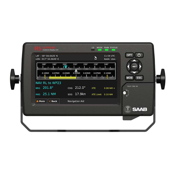
- Page 46 SUPREME - Navigation System MkII Navigation Aid The Navigation Aid view presents fundamental navigation data and aids the user in navigating towards a waypoint and following a route. It presents information such as the bearing and range to the next waypoint, the ship’s current course over ground (COG) and speed over ground (SOG) and current cross-track error (if sailing on a route).
- Page 47 SUPREME - Navigation System MkII Figure 33 – Navigation Plot The next waypoint in the route is marked with a double circle and the currently active leg is shown in cyan colour. Other legs are shown in magenta colour and their waypoints are marked with a single circle.
- Page 48 SUPREME - Navigation System Navigation Info The Navigation Info view presents fundamental navigation data and aids the user in navigating towards a waypoint and following a route. It presents information such as the bearing and range to the next waypoint, the ship’s current course over ground (COG) and speed over ground (SOG) and current cross-track error (if sailing on a route).
- Page 49 SUPREME - Navigation System Course to steer – The calculated course to steer compensates for the current set and drift and calculates a course to steer to make the COG match the BRG. Heading sensor input is required to calculate CTS. This value is outputted as the heading to steer value in the APB and HSC sentences.
- Page 50 SUPREME - Navigation System This sub view shows the estimated time of arrival (ETA) to the last waypoint in the current route if the current speed over ground (SOG) is maintained. It is also possible for the user to set a “Target ETA”, i.e. a desired time when the last waypoint in the current route should be reached.
-
Page 51: Voyage Menu
SUPREME - Navigation System 8.1.6.6 Next Waypoint Plot This sub view shows a plot of the remaining part of the current leg as well as the next leg. The plot will automatically adjust the zoom level when the ship is closing on the next waypoint. To view a more detailed plot of the entire route and to zoom manually, see section 8.1.5. - Page 52 SUPREME - Navigation System The Route List view presents the routes currently stored in the R5 SUPREME CDU, and provides sub views to view and edit a route as well as creates new routes. The Route List view also contains functionality to delete routes and find a route by name. Figure 40 –...
- Page 53 SUPREME - Navigation System Figure 42 – Sail To View Either an existing waypoint can be used, or a new destination waypoint can be created. The new waypoint can be created by either specifying latitude and longitude or by specifying range and bearing from current position.
- Page 54 SUPREME - Navigation System Create a new waypoint by specifying bearing and range 1. Press the button “Create New WPT” to show the Create New Waypoint view. 2. Press on the “Name” edit field and enter a new name for the destination. 3.
- Page 55 SUPREME - Navigation System waypoints and change settings such as navigation algorithm, RAIM level and XTE limit for each leg in the route. The route name can also be modified. A waypoint or route inserted first or last in the route being edited results in the creation of a new leg connecting it to the edited route.
- Page 56 SUPREME - Navigation System Insert waypoints into the route 1. Make sure that the Edit Route view shows the waypoints (press “Show WPs” if the leg view is shown). 2. Select the waypoint in the route which new waypoints should be inserted before or after.
- Page 57 SUPREME - Navigation System Figure 50 – Insert Route View 5. Highlight the desired route in the list and press “Insert” to insert all the waypoints from the chosen route into the route being edited. 6. Press “Save” in the Edit Route view to save changes in the edited route and exit to Route List view.
- Page 58 SUPREME - Navigation System 6. To change the XTE Limit for the leg, press the “XTE Limit” drop list and choose “XTE Limit”. A new edit field will appear. Click on the “Limit” edit field to input a desired XTE Limit.
- Page 59 SUPREME - Navigation System 8.2.1.4 Create a New Route The Create Route view is used to create a new route. A default name is supplied but should be changed to a descriptive name for the new route. A route can be created from the Route List view by pressing the button “Create”...
- Page 60 SUPREME - Navigation System 8.2.1.5 Find a Route by Name It is possible to search for a route in the route list by entering the name, if the route is found it will automatically be highlighted in the Route List view. 1.
- Page 61 SUPREME - Navigation System 8.2.1.9 Delete All Routes 1. Press the button “Route” followed by “Delete All”. 2. A confirmation popup will appear, press “Yes” to delete all the routes in the system. This will only delete the routes; the associated waypoints will still be available. Waypoint List Waypoints are the basis for ship navigation.
- Page 62 SUPREME - Navigation System 8.2.2.2 Edit a Waypoint 1. Select the desired waypoint in the list. 2. Press the button “WPT” followed by “Edit”. 3. Press the “Name” edit field to edit the name of the waypoint. 4. Press the “LAT” edit field to edit the latitude of the waypoint. 5.
- Page 63 SUPREME - Navigation System 4. Press the “LAT” edit field to enter the latitude of the waypoint. 5. Press the “LON” edit field to enter the longitude of the waypoint. 6. Press the button “Current Position” to fill in the current position as latitude and longitude for the waypoint.
- Page 64 SUPREME - Navigation System Note that meteorological effects (e.g wind and barometric pressure) as well as other factors not accounted for in the generalized tidal models may cause significant deviation between actual and predicted tide. 8.2.3.1 Calculation Method and Source Data for Tide The tidal predictions are calculated by the so called ‘simplified harmonic method’.
- Page 65 SUPREME - Navigation System 8.2.3.2 Input of Tidal Parameters Tidal data for a new port is entered as follow: Enter the Tide Plot view by pressing Main Menu Voyage Tide. The Tide Plot view will be displayed as shown below: Figure 59 –...
- Page 66 SUPREME - Navigation System Some ports have season or fortnightly variations in mean level and harmonic constants. If so, such variations can be input by selecting “Use Table…” in the corresponding drop list for the parameter. Figure 62 – Add Port – Input Seasonal Variations A new view will be shown where the variation values from the “Admiralty Tide Tables”...
- Page 67 SUPREME - Navigation System The following data can be input for each port: Port No. from ATT part III. Name Place name from ATT part III. UTC offset time zone (UTC time – Local Time) in hours and Zone minutes from ATT part III. This information is important since ATT data is referenced to a local time in port with this offset from UTC.
- Page 68 SUPREME - Navigation System K1 g Harmonic constant from ATT part III. K1 H.m Harmonic constant from ATT part III. O1 g Harmonic constant from ATT part III. O1 H.m Harmonic constant from ATT part III. Shallow water correction from ATT part III. Shallow water correction from ATT part III.
- Page 69 SUPREME - Navigation System Figure 64 – Tide Plot The Tide Plot shows the predicted tides for the selected port and date. The port id and the port name are shown above the plot. The plot date is shown in the upper right corner. The turquoise dot in the plot marks the current time as derived from GNSS.
- Page 70 SUPREME - Navigation System Figure 66 – Tide Table 8.2.3.5 Units of Predicted Tide Predicted tide can be displayed in meters, feet or fathom units as defined by the ‘Depth Unit’ configuration parameter. This parameter is accessed from the Units Configuration view described in section 10.1.12.
- Page 71 SUPREME - Navigation System Figure 67 – Edit Port, Zone Setting Figure 68 – Time Zone Settings for the R5 SUPREME CDU Scheduled Alerts The Scheduled Alerts view allows the user to create and inspect alerts scheduled to activate alarms at certain points in time. There are two types of alerts that may be scheduled.
- Page 72 SUPREME - Navigation System Figure 69 – Scheduled Alerts View 8.2.4.1 Create Time Alert 1. To create a new time alert, press the button “Create Time Alert”. The Create Time Alert view is shown: Figure 70 – Create Time Alert View 2.
- Page 73 SUPREME - Navigation System Figure 71 – Create ETA Alert View 2. To edit the alert text that is shown in the popup and, press the “Alert Text” edit field. A virtual keyboard will appear. Enter the desired alert text and press enter on the virtual keyboard.
- Page 74 SUPREME - Navigation System Figure 72 – Sun Info View Sunrise The estimated time of the appearance of the sun’s upper circumferential edge as rises over the horizon. Sunset The estimated time of the disappearance of the sun's upper circumferential edge as it sets below the horizon.
- Page 75 SUPREME - Navigation System Figure 73 – Moon Info View Moonrise The estimated time of the appearance of the moon's upper circumferential edge as rises over the horizon. Moonset The estimated time of the disappearance of the moon's upper circumferential edge as it sets below the horizon.
-
Page 76: Status Menu
SUPREME - Navigation System Status Menu The Status Menu can be accessed from the Main Menu and contains views of currently active alarms, raw data, navigation status and information about the equipment’s hardware and software. Figure 74 – Status Menu GNSS / DGNSS Overview The GNSS/DNGSS Overview view is accessible by Main Menu ... - Page 77 SUPREME - Navigation System RAIM Accuracy Limit The currently used RAIM accuracy limit used in the RAIM calculations. See chapter 4 “Concepts and Terminology” for more information. RAIM Status The current RAIM status result which can be Safe, Unsafe or Caution. The RAIM status is also indicated by RAIM LED on the front of the R5 SUPREME CDU.
- Page 78 SUPREME - Navigation System Figure 76 – SBAS Info Satellite Info The Satellite Into view is accessible by Main Menu Status Navigation GNSS/DGNSS Satellite Info. The Satellite Info view shows information relating to GNSS satellites that the R5 Navigation Sensor is receiving or expecting to receive signals from.
- Page 79 SUPREME - Navigation System 8.3.3.1 Sky Plot From the Satellite Info view is the Sky Plot view accessible. In this view a sky maps is showing the estimated position of the satellites in form of colored targets/items, based on the received almanac.
- Page 80 SUPREME - Navigation System Closest Beacons This view is accessible by Menu Status Navigation GNSS / DGNSS Beacon Closest Beacon and shows a list of the ten closest beacon stations. To show more information about a particular Beacon station, select it in the list and press “Extended Info”. The currently used beacon station is marked with green colour in the list.
- Page 81 SUPREME - Navigation System The frequency tuning mode which can be Manual, Auto or (Freq) Mode: Database. Beacon receiver bit rate. Bitrate Beacon receiver bit rate selection mode: Manual or Auto. (Bitrate) Mode: Signal strength of the received beacon signal. Signal: Signal to noise ratio.
- Page 82 SUPREME - Navigation System Sensor will then try to tune the beacon receiver to the selected stations frequency. If the tuning was successful, the new station will be marked with green colour text in the beacon database list to indicate that it is currently used. Figure 82 –...
- Page 83 SUPREME - Navigation System Figure 84 – Trip Logs Press the button “Reset” to reset the trip log. If a valid position is available, it will be captured and used as the starting position for the trip log. If the system has no valid position, a start position will be captured the next time a valid position is available.
- Page 84 SUPREME - Navigation System Track Log View The Track Log View is accessible by Main Menu Status Navigation Track Log View. “Track Logs” on an existing SD-Card. The view list will This view allows the user to watch the just show the logs from an nmea-file including bypass of a waypoint.
- Page 85 This view is accessed from Main Menu Status SW/HW Info and displays the software and hardware revisions for the R5 SUPREME Navigation System. This information should always be provided when in contact with Saab AB (publ) TransponderTech support. The button “Show/Hide Ext. Info” is used to switch on/off additional information that is rarely needed.
-
Page 86: Dgnss Messages (Dgnss Version Only)
SUPREME - Navigation System DGNSS Messages (DGNSS version only) It is possible to receive DGNSS messages via the beacon receiver (RTCM, Type 16 messages). When a new DGNSS message received, a DGNSS message icon will be displayed in the status bar. All received messages can be read in the DGNSS Message view, accessed from Main Menu ... -
Page 87: Web Interface
SUPREME - Navigation System 9 WEB INTERFACE The R5 Navigation Sensor has a web interface, just requiring an Ethernet connection, which gives the user a possibility to operate and configure the sensor without needing a R5 SUPREME CDU. The interface is accessible by the most commonly browsers, by only enter the R5 Sensor’s IP address which in default is set to be 172.16.0.4 on Eth1 and 172.17.0.4 on Eth2. -
Page 88: Configuration View
SUPREME - Navigation System Configuration View In the Configure view the R5 navigation Sensor can be set to work as desired. For more information about configuration parameters related to: GNSS, see section 10.1.1 and 10.1.2 SBAS, see section 10.1.3 ... -
Page 89: Version View
In the Version view information about the hardware and software, in both the main unit and the integrated receivers, is displayed. This information should always be provided when in contact with Saab AB (publ) TransponderTech support. Figure 93 - Web Interface, Version view Maintenance View The “Maintenance”... - Page 90 R5 Navigation Sensor. There is also a possibility to reset the unit’s password to default (no password), but to be able to perform that operation one must contact Saab AB (publ) TransponderTech’s support service for receiving a restore code. Refer section 13.5.
-
Page 91: Configuration
SUPREME - Navigation System CONFIGURATION This chapter describes what configuration possibilities the R5 SUPREME Navigation System has. 10.1 Configuration Parameters The following sections lists and describes all the parameters that can be configured in the R5 SUPREME Navigation System. All the configuration sub menus can be found under Main Menu ... - Page 92 SUPREME - Navigation System All legs of a newly created route as well as incoming routes on serial interface will use the default RAIM level unless specifically changed in the route. Navigation Algorithm This is the default navigation algorithm that will be used for bearing and range calculation by the system if no other navigation algorithm is set on the on the current leg of the active route.
- Page 93 SUPREME - Navigation System RTE/Rnn WP Limit Determines the maximum number of remaining waypoints in the active route that shall be transmitted in RTE and Rnn messages. Status Information The Status Information parameter defines whether current position (when available) from a navigation sensor or the name of the next waypoint is to be displayed in the status bar at the upper left corner of the R5 SUPREME CDU.
- Page 94 SUPREME - Navigation System SBAS. This setting makes the system use SBAS satellite signals as source for differential corrections. IN IN 1 5. These settings will command the system to apply external differential corrections, received in RTCM SC-104 format, on the selected input port. None.
- Page 95 SUPREME - Navigation System however recommended that you test how the revised value works in practice. COG smoothing = 10 / maximum rate of change in course (in °/s). Note: The ship needs to be moving to calculate a valid COG value.
- Page 96 SUPREME - Navigation System SBAS This view is accessed by pressing Main Menu Maintenance Configuration GNSS/DGNSS SBAS Parameter Name Description PRN Search Mode Change between Automatic or Manual search mode. In Manual search mode, the R5 Navigation sensor will try to acquire signals from satellites with id (PRN) numbers input by the parameters PRN 1 and PRN 2 in the view.
- Page 97 SUPREME - Navigation System In Database mode, the receiver will search for the closest station based on its current location and distance to the internal list of station locations. The frequency and bit rate specified in the station database will be used and therefore these parameters are hidden when the Tuning Mode parameter is set to Database (Auto).
- Page 98 SUPREME - Navigation System GNSS Antenna Position The GNSS Antenna Position feature can be configured for inform the environment about the exact location of the antenna on-board the ship. By enabling the Position, will the inputted position be included in the configurable output sentence “POS” (For more info about the POS sentence see section 14.2 and 15.1.13).
- Page 99 SUPREME - Navigation System Ship Dimension The Ship Dimension feature can be configured for inform the environment about the ship’s size. By enabling the Ship Dimension, will the inputted dimensions be included in the configurable output sentence “POS” (For more info about the POS sentence see section 14.2 and 15.1.13).
- Page 100 SUPREME - Navigation System NOTE: True heading data is required to calculate position offset. CCRP will be zero if there is no valid heading data. Figure 97 – Consistent Common Reference Point (CCRP) This view accessible by pressing Main Menu Maintenance Configuration GNSS/DGNSS ...
- Page 101 SUPREME - Navigation System There is no default sensor password in the R5 Navigation Sensor. No password set, no password required. It is possible to restore the Navigation Sensor’s Restore Password Key password with a secret restore key. To obtain the restore key, contact TransponderTech Support and be prepared to provide the serial number of the unit.
- Page 102 SUPREME - Navigation System To switch between day/night mode and to tune backlight for buttons, LCD and LEDs, enter the Visual Settings view which is accessed from Main Menu Maintenance Configuration Display Visual Settings Parameter Name Description Mode There are two available display backlight modes;...
- Page 103 SUPREME - Navigation System Sound This view is accessed by pressing Main Menu Maintenance Configuration Display Sound Parameter Name Description Alarm Volume Determines the volume of the R5 SUPREME CDU internal speaker. Alarm Waiting For ACK Determines how the R5 SUPREME CDU speaker should behave when an alarm is active and waiting for acknowledgement.
- Page 104 SUPREME - Navigation System Units This view is accessed by pressing Main Maintenance Configuration Display Units Parameter Name Description Range Unit This parameter determines the unit of the range values displayed in R5 SUPREME CDU like e.g. the range to the next waypoint.
- Page 105 SUPREME - Navigation System Calibration This view is accessed by pressing Main Menu Maintenance Configuration Calibrate Display Figure 100 – Calibration View Press on the crosshair each time it appears to calibrate the touch screen. Try to hit the centre of the cross as accurate as possible for the best possible calibration.
- Page 106 SUPREME - Navigation System The serial ports can be set to: 4800 bps 9600 bps 19200 bps 38400 bps 57600 bps 115200 bps The higher the baud rate, the more sentences can be output on the specific port. In the “Output Config” views (see section 10.1.25) an estimated port load is calculated depending on the selected baud rate and the configured output sentences.
- Page 107 SUPREME - Navigation System Navigation Sensor settings (Network) This view is accessed by pressing Main Menu Configuration Interface Network Navigation Sensor Settings Parameter Name Description LWE ID The unique ID that is used on the Light Weight Ethernet network.
- Page 108 SUPREME - Navigation System Turning “on” this parameter will activate the R5 Redundant Nav SUPREME Navigation System’s redundancy mode, which will require an additional setup of the R5 SUPREME Navigation System. Heading Input Port This view is accessed by pressing Main Maintenance Configuration Interface Input ...
- Page 109 SUPREME - Navigation System WPT/RTE Data Port This view is accessed by pressing Main Maintenance Configuration Interface Input Depth Data Port Parameter Name Description Input Port Specifies the input port that should be used for input of ...
- Page 110 SUPREME - Navigation System Output The Output Configuration view is used to configure which NMEA sentences is output on the R5 Navigation Sensor*s Output Ports and the Light Weight Ethernet port on both the R5 Navigation Sensor and the R5 CDU, and how often they are sent. The views are accessed by pressing Main Menu ...
- Page 111 SUPREME - Navigation System AAM/APB/BOD/HCS/RMB/XTE Navigation sentences that the R5 Navigation Sensor is capable to output. WPL/RTE(Upload) Either the sentences are “Disabled” and thereby not WPL/RTE(Working) outputted or set to “Every Second” and outputted each WPL/RNN(Working) second. See section 15.2 for message examples and explanatory.
-
Page 112: Slave Displays And Redundant Systems
SUPREME - Navigation System SLAVE DISPLAYS AND REDUNDANT SYSTEMS The R5 SUPREME Navigation System can be used in different system configurations such as slave display systems or redundant navigation systems. R5 SUPREME CDU units can use LWE to synchronize configurations, waypoints and routes. This chapter describes how to setup and configure such systems. - Page 113 SUPREME - Navigation System Power up the R5 SUPREME CDU slave display in Wizard mode. If the R5 SUPREME CDU is a new unit it will automatically start in this mode. If the R5 SUPREME CDU already is configured, go to Main Menu Maintenance Configuration ...
- Page 114 SUPREME - Navigation System Make sure that the R5 SUPREME CDU slave has a configured IP Address and a unique LWE Id. Figure 104 – Slave, Network Configuration The R5 SUPREME CDU slave must now select the master R5 SUPREME CDU in the Select CDU Master view.
- Page 115 SUPREME - Navigation System Set the parameter “Redundant Nav” to On. Highlight each slave unit in the list, press on the “Select/Deselect” button, and make sure that all slaves that should be synchronized with the master are marked as “Selected”...
-
Page 116: Redundant Navigation Systems
SUPREME - Navigation System 11.2 Redundant Navigation Systems In a redundant setup, each R5 SUPREME CDU shall be connected a separate R5 Navigation Sensor, by a common network, which provides the GNSS data. The common network is also need for the R5 SUPREME CDUs in order to synchronize configuration parameters, waypoint and route databases as well as the active route. -
Page 117: Synchronized Items
SUPREME - Navigation System Set the parameter “Redundant Nav” to On. Highlight each unit that should be included in the redundant setup in the list and press on the “Select/Deselect” button and make sure that all units that should be synchronized are marked as “Selected”... -
Page 118: Maintenance
SUPREME - Navigation System 12 MAINTENANCE Saab AB (publ) TransponderTech is very keen to continue ensuring our products stay the best in the market. Therefore, the development of our products continues throughout their lifecycle, with SW featuring new features, fixes and compliance to new standards. Two to three SW releases per year is normal. -
Page 119: Upgrade R5 Navigation Sensor Software
SUPREME - Navigation System To perform a software update from inside the system, follow the instructions in the Update Software view, which are accessible from Main Menu Maintenance Update CDU Figure 110 - Update Software 12.2 Upgrade R5 Navigation Sensor Software The software in the R5 Navigation Sensor is easily upgraded either via the USB Host interface located behind the front hatch on the CDU, or the “Maintenance”... - Page 120 SUPREME - Navigation System Figure 112 – Select Load File From USB When the load file been selected press the “Done” button followed by the “Start Upgrade” button in the Update Navigation Sensor SW view and wait for the update process to finish. Figure 113 - Update Navigation Sensor SW, Update process See section 9.4.2 for description of performing a software update via the web-interface.
-
Page 121: Save/Load Config To/From Usb Memory
SUPREME - Navigation System 12.3 Save/Load Config to/from USB memory Figure 114 – Load/Save Configuration Menu The R5 SUPREME Navigation System has the capability to save configuration of the CDU and the R5 Navigation Sensor to a USB memory. The configuration file can be used as backup so that can be restored to a previous configuration;... - Page 122 SUPREME - Navigation System To view the contents of a sub folder, mark the folder in the list and press the button “Open” using the touch interface, or use the arrow keypad and press ENTER. To go back to the previous folder, use the touch interface or the arrow keypad to press the “Up”...
- Page 123 SUPREME - Navigation System back to the previous folder, use the touch interface or the arrow keypad to press the “Up” button in upper right corner of the view. 4. Press “Load” to load configuration from the selected file. A virtual keyboard prompting for the CDU password will appear.
- Page 124 SUPREME - Navigation System back to the previous folder, use the touch interface or the arrow keypad to press the “Up” button in upper right corner of the view. Select an existing Sensor configuration file to overwrite it or enter a new file name by pressing the “File Name”...
-
Page 125: Factory Reset
SUPREME - Navigation System To view the contents of a sub folder, mark the folder in the list and press the button “Open” using the touch interface, or use the arrow keypad and press ENTER. To go back to the previous folder, use the touch interface or the arrow keypad to press the “Up”... -
Page 126: Troubleshooting
SUPREME - Navigation System TROUBLESHOOTING One of the basic ideas with troubleshooting is to solve a supposed problem on site instead of immediately sending the suspected part for a costly repair. Solving a supposed problem would in this aspect mean both to rectify the real problem, but it could also mean that the suspected part is confirmed to be working or not. -
Page 127: Troubleshooting With The Sensor Leds
SUPREME - Navigation System RAIM LED (multi-coloured) This LED shows the current RAIM status of the R5 Navigation System. Green = “Safe” state, estimated position error is with a 95% probability smaller than the currently used RAIM level (shown in the upper right corner beneath the time in the CDU). Yellow = “Caution”... - Page 128 SUPREME - Navigation System Lost Connection to Display (ID 060) This alarm is active when connection is lost between R5 Navigation Sensor and CDU. NAV: HDOP Limit Exceeded (ID 151) This alarm is active when the HDOP (horizontal dilution of precision) exceeds 4.0. NAV: Position Data Lost (ID 152) This alarm is active when no valid position information is available from the R5 Navigation Sensor.
-
Page 129: Troubleshooting Via The Cdu
SUPREME - Navigation System NAV: RAIM Status - Unsafe (ID 164) This alarm is active when the RAIM status is unsafe. NAV: Redundant System Connection Lost (ID 166) No connection to an external R5 SUPREME Navigation system in redundant system configuration. -
Page 130: Contacting Support
Another option is to contact one of our OEM partners or affiliate service stations and request help. A list with our dealers, OEM partners and service stations can be found at our website, http://saab.com/, listed under the corresponding product. -
Page 131: Serial Communication Interfaces
SUPREME - Navigation System SERIAL COMMUNICATION INTERFACES This section describes the electrical characteristics of the serial interfaces in the R5 SUPREME Navigation System, as well as supported IEC 61162 input and output sentences. 14.1 Input Sentences The serial interfaces of the R5 SUPREME Navigation System supports receiving and interpreting the input sentences described in the table below. - Page 132 SUPREME - Navigation System same port, this isn’t recommended. See section 10.1.5 for configuration of GNSS antenna offset. Sentence Description GPS fix data GGA + Offset GPS fix data with GNSS antenna offset Geographic position, latitude/longitude GLL + Offset Geographic position, latitude/longitude with GNSS antenna offset GNSS fix data GNS + Offset GNSS fix data with GNSS antenna offset...
- Page 133 SUPREME - Navigation System Note 1: The ALR message provides current state of all external alarms with 3Hz every 30 seconds, and for individual alarms with a single message when an alarm state has changed. Note 2: Supported for NMEA backwards compliance. The recommendation is to use WPL/RTE.
-
Page 134: Interpretations Of Output Sentences
SUPREME - Navigation System INTERPRETATIONS OF OUTPUT SENTENCES 15.1 Output Sentences, GNSS All output sentences use the talker identifiers that can be seen in the table below. All of them starting a message with a ‘$’-character. Talker identifier System/Systems Global Position System (GPS) GLONASS GPS/GLONASS Galileo Position System... - Page 135 SUPREME - Navigation System ID number of most likely failed satellite Probability of missed detection for most likely failed satellite Estimate of bias Standard deviation of bias estimate GNSS System ID Always one (1) GNSS Signal ID Always one (1) GGA –...
- Page 136 SUPREME - Navigation System hhmms UTC of position s.ss Status Mode indicator GNS – GNSS fix data $--GNS,hhmmss.ss,llll.ll,a,yyyy.yy,a,c—c,xx,x.x,x.x,x.x,x.x,x.x,a Field Format Name Comment --GNS Sentence Id hhmms UTC of position s.ss llll.ll Latitude yyyy.yy Longitude c—c Mode indicator Total number of satellites HDOP Antenna altitude, meter Geodial separation...
- Page 137 SUPREME - Navigation System GSA – GNSS DOP and active satellites $--GSA,a,x,x.x,x.x,…,x.x,x.x,x.x,x.x Field Format Name Comment --GSA Sentence Id Mode Mode Satellite ID (1) Satellite ID (2) … … … Satellite ID (12) PDOP HDOP VDOP GNSS System ID GST – GNSS pseudorange error statistics $--GST,hhmmss.ss,x.x,x.x,x.x,x.x,x.x,x.x,x.x Field Format...
- Page 138 SUPREME - Navigation System GSV – GNSS satellites in view $--GSV,x,x,xx,xx,xx,xxx,xx....,xx,xx,xxx,xx,h Field Format Name Comment --GSV Sentence Id Total number of messages Message number Total number of satellites in view Satellite ID number (Satellite 1) Elevation, degrees (Satellite 1) Azimuth, degrees true (Satellite SNR (Satellite 1) Fields for all …...
- Page 139 SUPREME - Navigation System VTG – Course over ground and ground speed $--VTG,x.x,T,x.x,M,x.x,N,x.x,K,a Field Format Name Comment --VTG Sentence Id Course over ground, degrees true Course over ground, degrees magnetic Speed over ground, knots Speed over ground, km/h Mode indicator ZDA –...
-
Page 140: Output Sentences, Navigation
SUPREME - Navigation System Ship’s width/length validation flag Ship’s width Ship’s length Sentence status flag 15.2 Output Sentences, Navigation All output sentences use GN as talker identifier. ALR – Alarm State $--ALR,hhmmss.ss,xxx,A,A,c--c Field Format Name Comment --ALR Sentence Id hhmms UTC time of last condition s.ss change... - Page 141 SUPREME - Navigation System APB – Heading/Track Controller (Autopilot) Sentence B $--APB,A,A,x.x,a,N,A,A,x.x,a,c--c,x.x,a,x.x,a,a Field Format Name Comment --APB Sentence Id Status Status Magnitude of XTE Direction to Steer XTE units Status Status Bearing origin to destination c--c Destination waypoint ID Bearing, present position to destination Heading to steer to destination Mode indicator...
- Page 142 SUPREME - Navigation System BWC/BWR – Bearing and distance to waypoint $--BWC,hhmmss.ss,llll.ll,a,yyyy.yy,a,x.x,T,x.x,M,x.x,N,c--c,a $--BWR,hhmmss.ss,llll.ll,a,yyyy.yy,a,x.x,T,x.x,M,x.x,N,c--c,a Field Format Name Comment --BWC Sentence Id --BWR hhmms UTC of observation s.ss llll.ll Waypoint latitude yyyy.yy Waypoint longitude Bearing, degrees true Bearing, degrees magnetic Distance, nautical miles c--c Waypoint ID Mode indicator...
- Page 143 SUPREME - Navigation System RMB – Recommended minimum navigation information $--RMB,A,x.x,a,c--c,c--c,llll.ll,a,yyyy.yy,a,x.x,x.x,x.x,A,a Field Format Name Comment --RMB Sentence Id Status Cross track error, nautical miles Direction to steer L/R c--c Origin waypoint ID c--c Destination waypoint ID llll.ll Destination waypoint latitude yyyy.yy Destination waypoint longitude Range to destination, nautical...
-
Page 144: Output Sentences, Old Nmea Versions
SUPREME - Navigation System WPL – Waypoint location $--WPL,llll.ll,a,yyyy.yy,a,c--c Field Format Name Comment --VPL Sentence Id llll.ll Waypoint latitude, N/S yyyy.yy Waypoint longitude, E/W c--c Waypoint identifier XTE – Heading steering command $--XTE,A,A,x.x,a,N,a Field Format Name Comment --XTE Sentence Id Status Status Magnitude of cross-track error... -
Page 145: Interpretations Of Input Sentences
SUPREME - Navigation System INTERPRETATIONS OF INPUT SENTENCES Per default, any talker identifier is accepted. 16.1 Input Sentences ACK – Acknowledge alarm $--ACK,xxx Field Format Name Comment --ACK Sentence Id Used Corresponds to ALR message Alarm identifier number for alarm to acknowledge DBT –... - Page 146 SUPREME - Navigation System HDG – Heading, Deviation and Variation $--HDG,x.x,x.x,a,x.x,a Field Format Name Comment --HDG Sentence Id Used Magnetic sensor heading, Used degrees Magnetic deviation, degrees Used Magnetic variation, degrees Used HDT – Heading, True $--HDT,x.x,T Field Format Name Comment --HDG Sentence Id...
- Page 147 SUPREME - Navigation System THS – True Heading and Status $--THS,x.x,a Field Format Name Comment --THS Sentence Id Used Used if Status Heading, degrees true is set to ‘A’ Status Used WPL – Waypoint location $--WPL,llll.ll,a,yyyy.yy,a,c--c Field Format Name Comment --WPL Sentence Id Used...
-
Page 148: Input Sentences, Old Nmea Versions
SUPREME - Navigation System 16.2 Input Sentences, Old NMEA Versions Rnn – Routes (old NMEA versions) Can only be used for input of working (active) route. It is recommended to use the sentence instead if this sentence. Per default, any talker ID is accepted. $--Rnn,cccc,cccc,…,cccc Field Format... -
Page 149: Alternate System Setups
SUPREME - Navigation System ALTERNATE SYSTEM SETUPS 17.1 Redundant Navigation Systems Connected by Network R5 Control & R5 Control & Display Unit Display Unit Ethernet Ethernet Network R5 NAV sensor R5 NAV sensor 6 VDC 12/24 VDC Input 12/24 VDC Input 12/24 VDC Output 12/24 VDC Output 6 VDC... -
Page 150: Combined Ais And Navigation System Setup
SUPREME - Navigation System 17.3 Combined AIS and Navigation system setup Below details how to install a combined AIS and Navigation system, using one CDU. The CDU can act as both AIS MKD and Navigation system at the same time. The initial system setup wizard will activate the correct dialogs and menus. - Page 151 SUPREME - Navigation System R5 SUPREME Combined R5 NAV sensor Anten VHF Antenna 1PPS Output (D)GNSS Antenna 12/24 VDC Input 6 VDC Eth 1 AUX Power Output Output Port Power Out 2x Fuse Terminal holder Terminal 1-8 Alarm relay Input Port Power In Terminal Terminal 1-5...
-
Page 152: Technical Specifications
SUPREME - Navigation System TECHNICAL SPECIFICATIONS 18.1 R5 SUPREME CDU Physical Dimensions: Height: 140 mm Width: 255 mm Depth: 84 mm Weight: 1.6 kg Dimensions Height: 170 mm (incl. gimbal mount) Width: 295 mm Depth: 84 mm Weight 1.8 kg (incl. -
Page 153: R5 Navigation Sensor
SUPREME - Navigation System 18.2 R5 Navigation Sensor Physical Dimensions: Height: 52 mm Width: 261 mm Depth: 177 mm Weight: 1.75 kg Antenna Connector: TNC-Female Electrical Input Voltage: 24V DC (12 to 24 VDC) Nominal Power: 5.3 W (GNSS Version) 5.7 W (DGNSS Version) Nominal Current: 0.22A @ 24 VDC input (GNSS Version) -
Page 154: Internal Alarm Relay
SUPREME - Navigation System Internal GNSS Receiver Type: GPS, GLONASS, BeiDou, GALILEO L1/L2/L5, C/A code, 372 channel, parallel tracking Update Rate: 10 Hz max Horizontal Accuracy*: <0.4m, (95%), DGNSS < 1.3 m, (95%), GNSS Vertical Accuracy*: < 0.7 m, (95%), DGNSS <... -
Page 155: Electrical Interfaces
SUPREME - Navigation System ELECTRICAL INTERFACES 19.1 CDU Interfaces: CDU back: Ethernet port – RJ-45 100 MBit – IEC 61162-450 19.1.1.1 19.1.1.2 Power port In/Out Signal Name Signal Type R5 Power Cable PWR + 24 VDC Black PWG GND 0 VDC Brown Orange Table 9 –... - Page 156 SUPREME - Navigation System 19.1.2.1 USB Host Type A USB 2.0. Supports FAT32 file systems and USB keyboards 19.1.2.2 CDU Pilot Plug RS-422 Only active in “AIS” or “Combined” installations. This bidirectional port is routed over Ethernet to the Transponder. Figure 129 - CDU Pilot plug pin numbering Pilot plug Signal Type...
- Page 157 SUPREME - Navigation System Electrical Characteristics of CDU Serial ports The serial ports in the R5 SUPREME CDU are the Sensor Port, User Port 3 and user Port 4. 19.1.3.1 Output Drive Capacity Each serial port transmitter in the R5 SUPREME CDU can have a maximum of 25 listeners drawing 2.0 mA each.
-
Page 158: R5 Navigation Sensor Interfaces
SUPREME - Navigation System 19.2 R5 Navigation Sensor interfaces Internal circuit board layout: For detailed description of routed signals, see R5 Navigation Sensor interface specifications. Figure 131 Circuit Board Layout with additional Cover Board Marking Description PWR IN Terminal block for External 12-24VDC Isolated Input Power CDU PWR Terminal block for 12-24VDC Output Power, intended for the R5 Control &... - Page 159 SUPREME - Navigation System IN 1 Terminal block for input from Sensor 1 (Isolated) IN 2 Terminal block for input from Sensor 2 (Isolated) IN 3 Terminal block for input from Sensor 3 (Isolated) IN 4 Terminal block for input from Sensor 4 (Isolated) IN 5 Terminal block for input from Sensor 5 (Isolated) RELAY...
- Page 160 SUPREME - Navigation System Table 12 Terminals/Signal Names Terminal Marking Terminal Pin Signal Name PWR IN PWR IN CDU PWR CDU PWR RELAY Normally Closed RELAY Common RELAY Normally Open OUT 1 Tx - OUT 1 OUT 1 Signal GND OUT 2 Tx - OUT 2...
- Page 161 SUPREME - Navigation System Terminal Marking Terminal Pin Signal Name OUT 6 Signal GND OUT 7 Tx - OUT 7 OUT 7 Signal GND OUT 8 Tx - OUT 8 OUT 8 Signal GND IN 1 Rx - IN 1 IN 1 Signal GND IN 2...
- Page 162 SUPREME - Navigation System Electrical Characteristics of R5 Navigation Sensor serial ports The serial ports in the R5 Navigation Sensor are all the IN- and OUT ports. 19.2.4.1 Output Drive Capacity Each talker output can have a maximum of 10 listeners drawing 2.0mA. 19.2.4.2 Input Load Each listener draws less than 2mA @ 2V input voltage.
- Page 163 SUPREME - Navigation System Figure 134 – R5 Navigation Sensor Serial Interface Output Schematics Electrical Characteristics of R5 Navigation Sensor digital ports 19.2.5.1 1PPS Port The 1PPS port send out a 5V clock pulse every second, lasting for 1ms, when the system has “GNSS Fix”, with an accuracy of 50 ns and detection on rising edge.
-
Page 164: Mechanical Drawings
SUPREME - Navigation System MECHANICAL DRAWINGS 20.1 CDU Physical Size and Mechanical Drawing Figure 135 – R5 SUPREME CDU Mechanical Drawing (mm) MECHANICAL DRAWINGS 7000 118-383, P11A1 Page 164... -
Page 165: Cdu Panel Mount Cutout Hole Dimensions
SUPREME - Navigation System 20.2 CDU Panel Mount Cutout Hole dimensions MECHANICAL DRAWINGS 7000 118-383, P11A1 Page 165... -
Page 166: Cdu Mounting Frame Cutout And Dimensions
SUPREME - Navigation System 20.3 CDU Mounting Frame cutout and dimensions Figure 136 – R5 SUPREME CDU, Mounting frame dimensions Figure 137 – R5 SUPREME CDU, Cut-out Measurements for Panel Flush Mount (mm) MECHANICAL DRAWINGS 7000 118-383, P11A1 Page 166... -
Page 167: R5 Navigation Sensor Size And Mechanical Drawing
SUPREME - Navigation System 20.4 R5 Navigation Sensor Size and Mechanical Drawing Figure 138 – R5 Navigation Sensor Measuements (mm) MECHANICAL DRAWINGS 7000 118-383, P11A1 Page 167... -
Page 168: Mgl-5 Antenna Physical Size And Mechanical Drawing
SUPREME - Navigation System 20.5 MGA-3 / MGL-5 Antenna Physical Size and Mechanical Drawing MECHANICAL DRAWINGS 7000 118-383, P11A1 Page 168... -
Page 169: Glossary
SUPREME - Navigation System GLOSSARY Acknowledgement AFSK Audio Frequency Shift Keying Automatic Identification System Antenna Application ARPA Automatic Radar Plotting Aid Bearing Base Station Control and Display Unit Channel Course Over Ground Comm Communication DGNSS Differential Global Navigational Satellite System Disp Display Dilution Of Precision... - Page 170 SUPREME - Navigation System Latitude Light Emitting Diode Local Longitude Light Weight Ethernet Message Minimum Keyboard and Display MSAS MTSAT Satellite Augmentation System (Japan) NMEA National Marine Electronics Association MMSI Maritime Mobile Service Identity Not available North East Non-Volatile Memory Position RAIM Receiver Autonomous Integrity Monitoring...
-
Page 171: Appendix B - License
APPENDIX B - LICENSE The R5 SUPREME CDU runs on a Linux operating system which is licensed with GNU General Public License. The source code of the Linux kernel can be obtained by contacting Saab AB (publ), TransponderTech AB: Saab AB (publ),TransponderTech Låsblecksgatan 3... - Page 172 SUPREME - Navigation System In addition, mere aggregation of another work not based on the Program with the Program (or with a work based on the Program) on a volume of a storage or distribution medium does not bring the other work under the scope of this License. 3.
- Page 173 SUPREME - Navigation System GNU General Public License for more details. You should have received a copy of the GNU General Public License along with this program; if not, write to the Free Software Foundation, Inc., 51 Franklin St, Fifth Floor, Boston, MA 02110-1301 Also add information on how to contact you by electronic and paper mail.
Need help?
Do you have a question about the R5 SUPREME MkII and is the answer not in the manual?
Questions and answers