Table of Contents
Advertisement
Model No. FMTK74817.1
USER'S MANUAL
Serial No.
Write the serial number in the space
above for reference.
Serial Number
Decal
QUESTIONS?
If you have questions, or if parts
are damaged or missing,
please see HOW TO CONTACT
CUSTOMER CARE on the back
cover of this manual.
CAUTION
Read all precautions and instruc-
tions in this manual before using
this equipment. Keep this manual
freemotionfitness.com
for future reference.
Advertisement
Table of Contents

Related Manuals for Freemotion FMTK74817.1


Summary of Contents for Freemotion FMTK74817.1
- Page 1 Model No. FMTK74817.1 USER’S MANUAL Serial No. Write the serial number in the space above for reference. Serial Number Decal QUESTIONS? If you have questions, or if parts are damaged or missing, please see HOW TO CONTACT CUSTOMER CARE on the back cover of this manual.
-
Page 2: Table Of Contents
LIMITED WARRANTY............. . . Back Cover FREEMOTION is a registered trademark of ICON Health & Fitness, Inc. -
Page 3: Important Precautions
FreeMotion Fitness assumes no responsibility for personal injury or prop- erty damage sustained by or through the use of this product. - Page 4 20. Keep fingers, hair, and clothing away from 25. Never insert or drop any object into any the moving walking belt. opening on the incline trainer. 21. The incline trainer is capable of high speeds. 26. Make sure to perform all maintenance proce- Adjust the speed in small increments to dures outlined in this manual.
-
Page 5: Warning Decal Placement
WARNING DECAL PLACEMENT These drawings show the location(s) of the warning decal(s). If a decal is missing or illegible, see the back cover of this manual and request a free replacement decal. Apply the decal in the location shown. Note: The decal(s) may not be shown at actual size. Note: There is one decal on each side... -
Page 6: Before You Begin
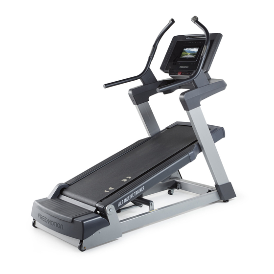
BEFORE YOU BEGIN Thank you for selecting the revolutionary after reading this manual, please see the back cover FREEMOTION i11.9 INCLINE TRAINER. The i11.9 of this manual. To help us assist you, note the product ® INCLINE TRAINER provides an impressive selection of model number and serial number before contacting us. -
Page 7: Part Identification Chart
PART IDENTIFICATION CHART Use the drawings below to identify small parts used for assembly. The number in parentheses below each draw- ing is the key number of the part, from the PART LIST near the end of this manual. The number following the key number is the quantity used for assembly. -
Page 8: Assembly
ASSEMBLY • Assembly requires two persons. • Assembly requires the following tools: • Place all parts in a cleared area and remove the one 3/8" hex key packing materials. Do not dispose of the packing materials until you fi nish all assembly steps. one 7/32"... - Page 9 2. Partially tighten two 5/16" x 3/4" Screws (51) with two 5/16" Star Washers (61) into the Left Upright (149). Do not fully tighten the Screws yet. Then, partially tighten two 5/16" x 3/4" Screws (51) with one 5/16" Star Washer (61) as shown into the Left Upright (149).
- Page 10 4. Partially tighten two 5/16" x 3/4" Screws (51) with two 5/16" Star Washers (61) into the Right Upright (150). Do not fully tighten the Screws yet. Then, partially tighten two 5/16" x 3/4" Screws (51) with one 5/16" Star Washer (61) as shown into the Right Upright (150).
- Page 11 6. With the help of a second person, set the Handrail Base (154) on the Uprights (149, 150). See the inset drawing. The 5/16" x 3/4" Screws (88) need to fit into the holes (D) in the bottom of the Handrail Base. Then, slide the Handrail Base forward.
- Page 12 8. Attach the Handrail Base Bottom Cover (155) with fourteen #8 x 3/4" Screws (16); start all fourteen Screws, and then tighten them. Do not overtighten the Screws. 9. Set the Right Handrail Assembly (113) on the right side of the Handrail Base (154). Attach the Right Handrail Assembly with two 5/16"...
- Page 13 10. Attach the Right Outer Cover (143) with three #8 x 3/4" Screws (16); do not overtighten the Screws. Next, attach the Right Inner Cover (145) with a 1/4" x 1" Screw (8); do not overtighten the Screw. Attach the Left Outer Cover (not shown) and the Left Inner Cover (not shown) as described above.
- Page 14 12. Attach the console assembly (F) with four 5/16" x 3/4" Screws (51) and four 5/16" Star Washers (61). Torque the Screws to 17 pound-feet (23 Newton-meters). 13. Attach the Console Back (5) to the console assembly (F) with four #8 x 3/4" Screws (16); start all four Screws, and then tighten them.
- Page 15 14. Attach the Left Upright Cover (151) to the Left Upright (149) with three #8 x 3/4" Screws (16); start all three Screws, and then tighten them. Do not overtighten the Screws. Attach the Right Upright Cover (not shown) to the Right Upright (not shown) as described above.
-
Page 16: How To Move The Incline Trainer
HOW TO MOVE THE INCLINE TRAINER Before moving the incline trainer, unplug the power cord. Note: It may be necessary to discon- nect a CATV cable and a network wire from the incline trainer, depending on how far the incline trainer will be moved. -
Page 17: How To Connect The Incline Trainer
This product has a cord with an an RF modulator to work correctly. RF modulators are not available from FreeMotion Fitness, but are avail- equipment-grounding conductor and a grounding plug. able at electronics stores. See the owner’s manual for... -
Page 18: How To Upgrade The Console
HOW TO UPGRADE THE CONSOLE Your incline trainer’s console has been preconfigured to operate with a digital TV (see the drawings below). To learn about the features of the console, see page 19. To learn about the features of the digital TV, see the user’s manual included with the digital TV. -
Page 19: How To Use The Console
HOW TO USE THE CONSOLE FEATURES OF THE CONSOLE When you use the manual mode, you can change the speed and incline of the incline trainer with the touch of The incline trainer console offers a selection of fea- a button. tures designed to make your workouts more effective and enjoyable. - Page 20 HOW TO TURN ON THE POWER HOW TO USE THE TOUCH SCREEN 1. Plug in the power cord. The console features a tablet with a full-color touch screen. The following information will help you become See HOW TO CONNECT THE POWER CORD on familiar with the tablet’s advanced technology: page 17.
- Page 21 HOW TO SET UP THE CONSOLE The browser will open to the iFit.com registration page. Follow the prompts on the screen to create Before using the incline trainer for the first time, set up your iFit account. the console. To use the manual mode, see page 22. To use an 1.
- Page 22 HOW TO USE THE MANUAL MODE Note: The first time you adjust the incline, you must first calibrate the incline system (see step 4 on 1. Insert the key into the console. page 29). See HOW TO TURN ON THE POWER on page 5.
- Page 23 If desired, adjust the volume by pressing the Vol 7. Turn on the fan if desired. increase and decrease buttons on the console. The fan features several speed settings. Press the To pause the workout, touch one of the menu but- fan buttons repeatedly to select a fan speed or to tons or press the Stop button on the console.
- Page 24 HOW TO USE AN ONBOARD WORKOUT If the speed and/or incline settings are too high or too low at any time during the workout, you can 1. Insert the key into the console. override the settings by pressing the Speed or Incline buttons.
- Page 25 HOW TO USE A SET-A-GOAL WORKOUT The workout will function in the same way as the manual mode (see pages 22 and 23). 1. Insert the key into the console. The workout will continue until you reach the goal See HOW TO TURN ON THE POWER on page 20. that you set.
- Page 26 HOW TO USE AN IFIT WORKOUT For more information about the iFit workouts, please see iFit.com. Note: To use an iFit workout, you must have access to a wireless network (see HOW TO USE THE When you select an iFit workout, the screen will WIRELESS NETWORK MODE on page 30).
- Page 27 HOW TO USE THE EQUIPMENT SETTINGS MODE 5. Select a timezone. The console features an equipment settings mode Touch the Timezone button. Select your local time- that allows you to select a language and the unit of zone to have the console sync to your local time. measurement, to turn on and turn off the display demo Then, touch the back button.
- Page 28 9. Enable or disable the web browser. Touch the Workout Time Limit button. To enable the workout time limit, touch the Enable checkbox. You can disable the console’s web browser, which Then, touch the increase and decrease buttons to will help to restrict the bandwidth used on your select the amount of time allowed for each user.
- Page 29 HOW TO USE THE MAINTENANCE MODE 4. Calibrate the incline system of the incline trainer. The console features a maintenance mode that allows you to update the console firmware, calibrate the Touch the Calibrate Incline button. Then, touch the incline of the incline trainer, calibrate the screen, view Begin button to calibrate the incline system.
- Page 30 HOW TO USE THE WIRELESS NETWORK MODE An information box will ask if you want to con- nect to the wireless network. Touch the Connect The console features a wireless network mode that to Wi-Fi button to connect to the network or touch allows you to set up a wireless network connection.
- Page 31 HOW TO USE THE INTERNET BROWSER To enter a different web address in the URL bar, first, slide your finger down the screen to view the URL bar, Note: To use the browser, you must have access to a if necessary. Then, touch the URL bar, use the key- wireless network including an 802.11b/g/n router with board to enter the address, and touch the Go button.
-
Page 32: Preventive Maintenance
PREVENTIVE MAINTENANCE Regular maintenance is necessary for optimal perfor- 2. Unplug the power cord. Next, remove the 3/8" x mance and long life of the incline trainer. Please read 1 1/4" Screws (37), and lift off the Motor Hood (75). and follow all instructions below. - Page 33 REPLACING THE WALKING PLATFORM AND THE 2. Remove the 3/8" x 1 1/4" Screws (37) and lift off WALKING BELT the Motor Hood (75). Inspect the walking platform periodically for wear. If there is any wood showing through the phenolic coat- ing, or if the surface is damaged, the walking platform should be turned over or replaced.
- Page 34 If you are turning over or replacing the Walking 6. Lift the right or left edge of the Walking Belt (18) Platform (23), go to step 5. and look for a small arrow printed on the under- side of the Walking Belt; move the Walking Belt, If you are replacing only the Walking Belt if necessary, as you look for an arrow.
- Page 35 7. Center the Walking Belt (18), if necessary (see LUBRICATING THE WALKING BELT pages 37 and 38). Then, plug in the power cord, step onto the foot rails, insert the key into the con- Your incline trainer features a walking belt coated with sole, and press the Start button.
-
Page 36: Preventive Maintenance Record
PREVENTIVE MAINTENANCE RECORD Photocopy this form and use it to record the preventive maintenance performed on the incline trainer. Each copy of the form can be used for six months (26 weeks). When maintenance is performed, write the date in the appro- priate spaces. -
Page 37: Troubleshooting
TROUBLESHOOTING MAINTENANCE SYMPTOM: The power turns off during use Regular maintenance is important for optimal per- a. Check the power switch located on the incline formance and to reduce wear. Inspect and properly trainer near the power cord (see drawing c at the tighten all parts each time the incline trainer is used. - Page 38 b. If the walking belt has shifted to the left: SYMPTOM: The walking belt stops or the incline Remove the key and unplug the power cord. cannot be adjusted even though the console Using a 7/32" hex key, turn the roller adjustment remains lit screws in the directions shown, 1/4 of a turn each.
-
Page 39: Exercise Guidelines
EXERCISE GUIDELINES Burning Fat—To burn fat effectively, you must exer- WARNING: cise at a low intensity level for a sustained period of Before beginning this time. During the first few minutes of exercise, your or any exercise program, consult your physi- body uses carbohydrate calories for energy. - Page 40 SUGGESTED STRETCHES The correct form for several basic stretches is shown at the right. Move slowly as you stretch —never bounce. 1. Toe Touch Stretch Stand with your knees bent slightly and slowly bend forward from your hips. Allow your back and shoulders to relax as you reach down toward your toes as far as possible.
-
Page 41: Part List
PART LIST Model No. FMTK74817.1 R0518A Key No. Qty. Description Key No. Qty. Description Side Cover 5/16" x 3/4" Screw #8 x 1/2" Machine Screw Drive Motor Center Isolator Drive Motor Isolator 3/8" Jam Nut 3/4" x 1/2" Screw Console Back Torsion Bar Bushing 1/4"... - Page 42 Key No. Qty. Description Key No. Qty. Description Filter Frame Crossbar Cap #6 x 1/2" Screw M3 x 8mm Bolt 1/2" Jam Nut 98ºC Thermal Switch #10 Nut M3 Nut Key/Clip Switch Bracket Cotter Pin #8 x 3/4" Console Screw Left Outer Cover #8 x 1/2"...
-
Page 43: Exploded Drawing
EXPLODED DRAWING A Model No. FMTK74817.1 R0518A... - Page 44 EXPLODED DRAWING B Model No. FMTK74817.1 R0518A...
- Page 45 EXPLODED DRAWING C Model No. FMTK74817.1 R0518A...
- Page 46 EXPLODED DRAWING D Model No. FMTK74817.1 R0518A...
- Page 47 EXPLODED DRAWING E Model No. FMTK74817.1 R0518A...
-
Page 48: How To Contact Customer Care
WARRANTY PERIODS AND COVERAGE 2. Pick-up, delivery, or freight charges involved with a repair. FreeMotion Fitness warrants this product to be free from 3. Any problem as a result of improper assembly or delivery. defects in workmanship and material under normal use and service conditions.
Need help?
Do you have a question about the FMTK74817.1 and is the answer not in the manual?
Questions and answers