Advertisement
Quick Links
Download this manual
See also:
Operating Manual
Advertisement

Related Manuals for WOOSIM PORTI-PC40


Summary of Contents for WOOSIM PORTI-PC40
- Page 1 PORTI-PC40 MODEL (2 Inch Printer with MSR ) WOOSIM SYSTEM Inc. #501, Daerung Technotown 3th, 448, Gasan-Dong, GeumChun-Ku, Seoul, Korea Tel : +82-2-2107-3700 Fax : +82-2-2107-3707 URL: http://www.woosim.com All specifications are subjected to change without notice...
- Page 2 2005 by Woosim System Inc. All rights reserved. The information contained in this manual is the property of Woosim System Inc. and may not be reproduced in whole or in part without the prior written permission of Woosim System Inc.
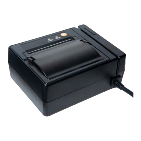
- Page 3 Introduction The Porti-PC40 is the ideal solution for Mobile banking system , Retail, point of sales, Credit card Transaction, other traveling and mobile computing etc. The general features of Porti-PC40 printer are as follows: Pocket size(105 x 80.4 x 45.7mm) Light weight(286g) for true mobility.
- Page 4 Please follow the precautions below to enjoy and maintain the full performance of the printer. Using the Printer Be careful not to drop or bump the printer on a hard surface. Do not install the printer in direct sunlight or such areas. Suitable environment for the use of the printer is as follows : Operating temperature : -10°C to 40°C Relative humidity : 10% to 90% (no condensation)
-
Page 5: Table Of Contents
CONTENTS 1. Outline .............................7 1.1. Model classifications ......................7 1.2. Specifications........................8 2. Setting up the printer ........................9 2.1. Unpacking..........................9 2.2. Outer appearances and part name ..................10 2.3. Dimensions .........................11 2.4. Installing or replacing the paper roll ...................12 2.5. Specified power supply.......................14 3. - Page 6 Appendix ............................66...
- Page 7 PORTI–PC40 Model name Interface Power...
-
Page 8: Dimensions
Item Description Printing method Direct thermal line printing Characters per line 42cpl Character size Eng. : 9*24dots, 12*24dots Kor. : 16*24dots, [24*24dots] Resolution 203dpi, 8dots/mm Print width 2-inch (48mm, 384dots) Printing speed 50mm / sec Dimensions 105 x 80.4 x 45.7 mm Weight 286g Interface... - Page 9 Your printer box should include these items. If any items are damaged or missing, please contact your dealer for assistance. PORTI-PC40 ROLL PAPER Operator’s Manual...
- Page 12 Note : Be sure to use paper rolls that meet the specifications. Do not use paper rolls that have the paper glued to the core because the printer cannot detect the paper end correctly. 1. Make sure that the printer is not receiving data; otherwise, data may be lost. 2.
- Page 13 5. Be sure to note the correct direction that the paper comes off the roll. 6. Pull out a small amount of paper and then close the cover, as shown. 7. Tear off the paper as shown.
- Page 14 The following specifications are requested for Power supply. VPP : DC 12-24V Standby 60mA and Max 3A...
- Page 15 The Porti-PC40 printer has an RS-232C serial interface is connected by means of a 9p D-sub. In the following table, the signals present on the connector are listed: Pin No. Name Direction Function Output Transmit Data Input Receive Data Ground 12V~24V/3A <D-Sub 9p Female >...
- Page 16 RS-232C Technical Specifications DATA TRANSFER RATE : 9600 Baud WORD LENGTH : 8 Data Bits 1 Stop Bit SIGNAL LEVELS : Mark or Logical 1 = -3 to -15 VDC Space or Logical 0 = +3 to +15VDC HANDSHAKING : XON / XOFF...
- Page 17 Button - FEED Button : Press the FEED button once to advance paper one line. You can also hold down the FEED button to feed paper continuously. Panel Lamp -POWER : The POWER lamp is on whenever the printer is on. -ERROR : This indicates an error such as paper end, or cover open, etc.
- Page 18 The self-test checks whether the printer has any problems. If the printer does not function properly, contact your dealer. The self-test checks the following; 1. Make sure paper roll has been installed properly. 2. Turn on the power while holding down the FEED button. The self-test begins. 3.
- Page 19 Type : Thermal Paper Paper width : 57mm : 65±5 Mm Paper thickness Outer diameter : Ø40mm or less Recording side : Outside of roll Cautions 1. Do not paste the paper to the core. And the roll paper which has Near end mark printing on its near end is recommended.
- Page 21 Command Name Function Type Page Horizontal tab Print position Print and line feed Print Print and return to standard mode Print DLE EOT Real-time status transmission Status Print data in page mode Print ESC FF ESC SP Set right-side character spacing Character Select print mode Character...
-
Page 22: Printing Position
Command Name Function Type Page Select print direction in page mode Print position ESC T ESC W Set printing area in page mode Print position Define user-defined bit-image Bit image ESC X 4 ESC \ Set relative print position Print position Print 2D barcode Barcode ESC Z... - Page 23 The PORTI-PC40 supports the following commands for printing character and advancing paper: Print and line feed ESC J Print and feed paper ESC d Print and feed n lines Print and return to standard mode(in page mode) ESC FF Print data in page mode...
- Page 24 ESC d n [Name] Print and feed n lines [Format] ASCII Decimal [Range] [Description] Prints the data in the print buffer and feeds n lines. [Note] 1) This command sets the print starting position to the beginning of the line. 2) This command does not affect the line spacing set by ESC 2 or ESC 3.
- Page 25 The PORTI-PC40 supports the following commands for setting line spacing. These commands only set the line spacing; they do not actually advance the paper. The line spacing set using these commands affects the results of LF and ESC d and paper feeding by using the FEED button.
- Page 26 3) The GS P command can change the horizontal (and vertical) motion unit. However, the value cannot be less than the minimum vertical movement amount, and it must be in even units of the minimum vertical movement amount. 4) In standard mode, the vertical motion unit (y) 5) In page mode, this command functions as follows, depending on the starting position of the printable area: When the starting position is set to the upper left or lower right of the printable area...
- Page 27 ESC SP n [Name] Set right-side character spacing. [Format] ASCII Decimal [Range] [Description] Sets the character spacing for the right side of the character to [n x horizontal or vertical motion units] inches. [Note] 1) The right side character spacing for double-width mode is twice the normal value.
- Page 28 Character set Character set U.S.A Sweden France Italy Germany Spain Norway Denmark Denmark II [Default] n = 0 ESC ! n [Name] Select print mode. [Format] ASCII Decimal [Range] [Description] Select print mode(s) using n as follows,. Off / On Decimal Function Character font A (12 x 24)
- Page 29 [Note] 1) When both double-height and double-width modes are selected, quadruple size characters are printed. 2) The printer can underline all characters, but can not underline the space set by 3) The thickness of the underline is that selected by ESC -, regardless of the character size.
- Page 30 following data is not underlined, and the underline thickness set before the mode is turned off does not change. The default underline thickness is 1 dot. 4) Changing the character size does not affect the current underline thickness. 5) Underline mode can also be turned on or off by using ESC !. Note, however, that the last received command is effective.
- Page 31 [Note] 1) Only the lowest significant bit of n is valid. 2) This command is enabled only when processed at the beginning of a line in standard mode. 3) When this command is input in page mode, the printer performs only internal flag operations.
- Page 32 Decimal Width Decimal Height 1 (normal) 1 (normal) 2 (double width) 2 (double height) Character Height Selection Character Width Selection [Notes] 1) This command is all characters effective 2) If n is outside of the defined range, this command is ignored. 3) In standard mode, the vertical direction is the paper feed direction, and the horizontal direction is perpendicular to the paper feed direction.
- Page 33 [Notes] 1) When the LSB is 0, white/black reverse printing mode is turned on. 2) When the LSB is 1, white/black reverse printing mode is turned off. 3) Only the lowest bit of n is valid. 4) This command is available for built in characters and user defined characters. 5) When white/black reverse printing mode is on, it also applied to character spacing set by ESC SP.
- Page 34 2) When the panel buttons are disabled, none of them are usable when the printer cover is closed. 3) In this printer, the panel buttons is the FEED button. 4) In the macro ready mode, the FEED button are enabled regardless of the settings of this command;...
- Page 35 [Description] Set the distance from the beginning of the line to the position at which subsequent characters are to be printed. [Notes] 1) The distance from the beginning of the line to the print position is [(nL + nH x 256) x (vertical or horizontal motion unit)] inches. 2) Setting outside the specified printable area are ignored.
- Page 36 2) Any setting that exceeds the printable are is ignored 3) When pitch N is specified to the right; nL + nH x 256 = N When pitch N is specified to the left (the negative direction), use the complement of 65536.
- Page 37 [Notes] 1) The command is enabled only when processed at the beginning of the line in standard mode. 2) If this command is input in page mode, the printer performs only internal flag operations. 3) This command has no effect in page mode. 4) This command executes justification in the printing area.
- Page 38 ESC D n1…nk NUL [Name] Set horizontal tab positions. [Format] ASCII n1…nk n1…nk Decimal n1…nk [Range] 1 <= n <= 255 0 <= k <=32 [Description] Set horizontal tab position [Notes] 1) n specifies the column number for setting a horizontal tab position from the beginning of the line.
- Page 39 GS L nL nH [Name] Set left margin. [Format] ASCII Decimal [Range] 255, 0 [Description] Set the left margin using nL and nH. [Notes]1) The left margin is set to [(nL+nHx256)] x (horizontal motion unit) inches. 2) This command is effective only processed at the beginning of the line in standard mode.
- Page 40 GS W nL nH [Name] Set printing area width [Format] ASCII Decimal [Range] 255, 0 [Description] Sets the printing area width to the area specified by nL and nH. [Notes] 1) The printing area width is set to [(nL+nHx256)] x horizontal motion unit inches. 2) This command is effective only processed at the beginning of the line.
- Page 41 If the printing area width cannot be extended sufficiently, the right space is reduced. 9) If the width set for the printing area is less than one line in vertical, the following processing is performed only on the line in question when data other than character data(e.g., bit image, user defined bit image) is developed: The printing area width is extended to the right to accommodate one line in...
- Page 42 dy = [(dyL + dyH * 256)] * (vertical motion unit) The printing area is set as shown in the figure below. [Note] 1) If this commands is input in standard mode, the printer executes only internal flag operation. This command does not affect printing in standard mode. 2) If the horizontal or vertical starting position is set outside the printable area, the printer stops command processing and processes the following data as normal data.
- Page 43 [Default] xL = xH = yL = yH = 0 dxL = 0, dxH = 2, dyL = 126, dyH = 6 [Reference] CAN, ESC L, ESC T, GS P ESC T n [Name] Select print direction in page mode [Format] ASCII Decimal...
- Page 44 [Notes] 1) When the command is input in standard mode, the printer executes only internal flag operation. This command does not affect printing in standard mode. 2) This command sets the position where data is buffered within the printing area set by ESC W.
- Page 45 5) The reference starting position is that specified by ESC T. 6) This command operates as follows, depending on the starting position of the printing area specified by ESC T; When the starting position is set to the upper left or lower right, this command sets the absolute position in the vertical direction.
- Page 46 4) Any setting that exceeds the specified printing area is ignored. 5) This command function as follows, depending on the print starting position set by ESC T; When the starting position is set to the upper left or lower right of the printing, the vertical motion unit (y) is used.
- Page 47 The PORTI- PC40 supports the following bit-image command. ESC * Select bit image mode ESC X 4 Define user-defined bit image ESC * m nL nH d1 dk [Name] Select bit-image mode. [Format] ASCII d1…dk 2A m d1…dk Decimal 42 m d1…dk [Range] m = 0,1,32,33...
- Page 48 4) If the bit-image data input exceeds the number of dots to be printed on a line, the excess data is ignored. 5) d indicates the bit-image data. Set a corresponding bit to 1 to print a dot or to 0 to not print a dot.
- Page 49 - When 8-dot bit image is selected - When 24-dot bit image is selected...
- Page 50 ESC X 4 x y d1…dk Define user-defined bit-image [Name] [Format] ASCII x y d1…dk x y d1…dk Decimal x y d1…dk ESC X 4 x y d1 ... d(x y) defines a user-defined bit image using x [Description] dots in the h direction and y dots in the v direction.
- Page 51 [Note] ESC X 4 is supported in Porti_W,S produced after August,2002, but it’s not supported in others yet. [Reference] ESC W, ESC O, FF...
- Page 52 The PORTI- PC40 supports the following status transmission command. DLE EOT EOT Real-time paper status transmission [Name] Real-time paper status transmission [Format] ASCII Decimal [Description] Real time paper status transmission [Note] DLE EOT EOT is supported only by PORTI_T80. 0 / 1 Status Roll end sensor : paper present Roll end sensor : paper not present...
-
Page 53: Barcode Commands
The PORTI- PC40 supports the following barcode commands. GS h Set barcode height GS w Set barcode width GS k Print bar code GS H Select printing position of Human Readable Interpretation (HRI) characters GS h n [Name] Set barcode height [Format] ASCII Decimal... - Page 54 GS k m d1 dk NUL GS k m n d1…dn [Name] Print barcode [Format] ASCII GS m d1…dk NUL m d1…dk 00 Decimal 29 m d1…dk 0 ASCII GS m n d1…dn m n d1…dn Decimal 29 m n d1…dn (k and d depends on the bar code system used.) [Range] (n and d depends on the bar code system used.)
- Page 55 Barcode System Number of characters Remarks UPC-A UPC-E EAN13 EAN8 CODE39 57, 65 d d = 32, 36, 37, 43, 45, 46,47 255 (even number) CODABAR 57, 65 d n 255 d = 36, 43, 45, 46, 47, 58 CODE93 n 255 d 127 CODE128...
- Page 56 processes the following data as normal data. 8) Be sure to keep spaces on both right and left sides of a bar code. Spaces are different depending on the types of the bar code. [Reference] GS h, GS w, GS H, ESC L, ESC W, ESC FF GS H n [Name] Turn HRI characters print mode ON/OFF...
-
Page 57: Macro Function Commands
The PORTI- PC40 supports the following macro function commands; GS : Start/end macro definition GS ^ Execute macro GS : [Name] Start/End macro definition [Format] ASCII Decimal [Description] Starts ends macro definition. [Notes] 1) Macro definition starts when this command is received during normal operation. Macro definition ends when this command is received during macro definition. - Page 58 GS ^ r t m [Name] Execute macro. [Format] ASCII r t m r t m Decimal r t m [Range] 0 <= r <= 255 0 <= t <= 255 m = 0, 1 [Description] Executes a macro. [Notes] 1) r specifies the number of times to execute the macro.
-
Page 59: Mechanism Control Commands
PC40 supports the following mechanism control commands; PORTI- GS V Select cut mode and cut paper ESC i Partial cut (One point center uncut) GS V m [N1ame] Select cut mode and cut paper [Format] ASCII Decimal [Range] n=0, n=1 [Description] GS V m select a paper cutting mode and then cut the paper. - Page 60 The PORTI-PC40 supports the following m commands; agnetic card reader ESC M C Set 2 track card reader mode. ESC M D Set 3 track card reader mode. ESC M E Set 2,3 track card reader mode. Cancel card reader mode...
-
Page 61: Card Specification
[Name] Cancel card reader mode. [Format] ASCII Decimal [Description] Cancel card reader mode. Card specification The table below summarizes the format of the data stored on each magnetic track. ISO-2 Track (ABA) ISO-3 Track (MINTS) Recording Density 75 BPI 210 BPI 40 characters 107 characters Recording Capacity... -
Page 62: Miscellaneous Function Commands
The PORTI- PC40 supports the following miscellaneous function commands; GS P Set horizontal and vertical motion units ESC @ Initialize printer ESC L Select page mode ESC S Select standard mode GS P x y [Name] Set horizontal and vertical motion units. [Format] ASCII Decimal... - Page 63 When the print starting position is set to the upper right or lower left of the printing area ESC T (data is buffered in the paper feed direction); Command using x : ESC 3, ESC J, ESC W, GS $, GS \ Command using y : ESC SP, ESC $, ESC W, ESC \ 4) The command does not affect the previously specified values.
- Page 64 4) This command sets the position where data is buffered to the position specified by ESC T within the printing area defined by ESC W. 5) This command switches the settings for the following commands (in which the values can be set independently in standard mode and page mode) to those for page mode;...
- Page 65 Set right-side character spacing : ESC SP Select default line spacing : ESC 2, ESC 3 6) The following commands are enabled only to set in standard mode. Set printing area in page mode : ESC W Select print direction in page mode : ESC T 7) The following commands are ignored in standard mode.
- Page 66 A. MISCELLANEOUS NOTES 1. Printer mechanism handing 1) Do not pull the paper out when the cover is closed. 2) Because the thermal elements of the print head and driver ICs are easy to break, so do not touch them with any metal objects. 3) Since the areas around the print head become very hot during and just after printing, do not touch them.
- Page 67 7) If the surface of thermal paper is scratched with a hard metal object such as a nail, the paper may become discolored. - Notes on thermal paper storage Since color development begins at 70 C (158 F), thermal paper should be protected from high temperature, humidity, and light, both before and after printing.
Need help?
Do you have a question about the PORTI-PC40 and is the answer not in the manual?
Questions and answers