Table of Contents
Advertisement
Quick Links
AVR364: MEGA-1284P Xplained Hardware
Features
®
®
• Atmel
megaAVR
ATmega1284P microcontroller
- Target controller
®
• Atmel AVR
AT32UC3B1256 32-bit microcontroller
- Board controller
- Communication gateway
•
Analog input (to ADC)
- Temperature sensor
- Light sensor
- RC filter
• Digital I/O
- Three mechanical buttons
- Four LEDs
- Four expansion headers
• Footprints for external memory
- Atmel AT45DB series DataFlash
- Atmel AT25DF series industrial standard serial data flash
• Touch
- One Atmel QTouch
1 Introduction
The Atmel MEGA-1284P Xplained evaluation kit is a hardware platform for
evaluating the
ATmega1284P
The kit offers a large range of features that enable the
started using
megaAVR
to integrate a
megaAVR
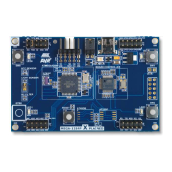
Figure 1-1. MEGA-1284P Xplained evaluation kit.
User's Guide
®
serial flash
®
button
MCU.
peripherals right away and to get an understanding of how
MCU in their own design.
megaAVR
user to get
8-bit Atmel
Microcontrollers
Application Note
Rev. 8377B-AVR-11/11
Advertisement
Table of Contents

Related Manuals for Atmel AVR364


Summary of Contents for Atmel AVR364
-
Page 1: Features
- Atmel AT25DF series industrial standard serial data flash • Touch ® - One Atmel QTouch button 1 Introduction The Atmel MEGA-1284P Xplained evaluation kit is a hardware platform for evaluating the ATmega1284P MCU. The kit offers a large range of features that enable the megaAVR... -
Page 2: Related Items
Atmel AVR Studio 4 (free IDE from Atmel) http://atmel.com/dyn/products/tools_card.asp?tool_id=2725&category_id=163&family _id=607&subfamily_id=760 Atmel AVR Dragon™ (on-chip programming and debugging tool) http://atmel.com/dyn/products/tools_card.asp?tool_id=3891&category_id=163&family _id=607&subfamily_id=760 Atmel AVR JTAGICE mkII (on-chip programming and debugging tool) http://atmel.com/dyn/products/tools_card.asp?tool_id=3353&category_id=163&family _id=607&subfamily_id=760 Atmel AVR ONE! (on-chip programming and debugging tool) http://atmel.com/dyn/products/tools_card.asp?tool_id=4279&category_id=163&family _id=607&subfamily_id=760 AVR364... -
Page 3: General Information
AVR364 3 General information This document targets the Atmel ATmega1284P evaluation kit revision 3, and parts of the document may, therefore, be inconsistent with earlier revisions of the product. For earlier revisions, please refer to the schematics, which is the only documentation available for these revisions. -
Page 4: Preprogrammed Firmware
LEDs. It also includes a boot loader (AVROSP) which allows the user to reprogram the ATmega1284P without using an external programmer. Please refer to the Atmel application note, AVR370: MEGA- 1284P Xplained Getting... -
Page 5: Power Supply
1.8V output and rerouting the power to the device (see schematic for an explanation). As some of the other ICs on the Atmel MEGA-1284P Xplained require 3.3V to operate correctly, these devices have to be removed. -
Page 6: Connectors
4 Connectors The Atmel MEGA-1284P Xplained kit has five 10-pin, 100mil headers. Two headers have a fixed communication interface (J1 and J4). One header has analog functionality (J2), and the last header (J3) has general purpose digital I/O. The 90° angled header is the... -
Page 7: I/O Expansion Headers
Please note that programming the Atmel AT32UC3B1256 using a programming tool will erase the boot loader. Please refer to the Atmel application note, AVR370: MEGA-1284P Xplained Getting Started Guide, for more details regarding how to program the onboard microcontrollers. 4.2 I/O expansion headers There are four available I/O expansion headers in the kit. - Page 8 Table 4-4. Atmel MEGA-1284P Xplained I/O expansion header – J3. ATmega1284P pin Shared with onboard functionality GPIO0 SW0, LED0 GPIO1 SW1, LED2 GPIO2 SW2, LED3 GPIO3 LED1 GPIO4 J4 (SPI SS1), DataFlash (SPI SS1) GPIO5 Filter input GPIO6 JTAG(TDO) GPIO7...
-
Page 9: Memories
AVR364 5 Memories The Atmel MEGA-1284P Xplained kit does not have any external memories mounted on the board. Footprints are available for adding either an industrial standard flash device or an Atmel proprietary serial DataFlash device. The footprints share the same SPI lines, including the chip select, and it is, therefore, not possible to mount devices on both footprints at the same time. -
Page 10: Miscellaneous I/O
LED shine brighter when the button is pressed and the LED is turned on. When the LED is off, any button press will light up the LED. The Atmel MEGA-1284P Xplained also has one dual LED mounted near the USB connector. This is the power and status LED, which is connected to the board controller. -
Page 11: Board Controller
AVR364 6.5 Board controller The Atmel AT32UC3B1256 board controller and the Atmel ATmega1284P connected through TWI, SPI, and USART interfaces. All interfaces can be used to communicate between the devices, but only the USART is implemented by default on the board controller. -
Page 12: Included Code Example
7 Included code example For documentation, help, and examples on the drivers used, please refer to the Atmel application note, AVR370: MEGA-1284P Xplained Getting Started Guide. 8 Revision history The kit revision can be identified by a barcode sticker on the bottom side of the kit. -
Page 13: Evaluation Board/Kit Important Notice
(WEEE), FCC, CE, or UL (except as may be otherwise noted on the board/kit). Atmel supplied this board/kit “AS IS,” without any warranties, with all faults, at the buyer’s and further users’ sole risk. -
Page 14: Table Of Contents
6.3 Analog I/O......................10 6.4 Touch......................... 10 6.5 Board controller ....................11 7 Included code example ..............12 8 Revision history ................12 8.1 Revision 3......................12 9 EVALUATION BOARD/KIT IMPORTANT NOTICE ......13 10 Table of contents ................. 14 AVR364 8377B-AVR-11/11... - Page 15 Disclaimer: The information in this document is provided in connection with Atmel products. No license, express or implied, by estoppel or otherwise, to any intellectual property right is granted by this document or in connection with the sale of Atmel products. EXCEPT AS SET FORTH IN THE ATMEL...
Need help?
Do you have a question about the AVR364 and is the answer not in the manual?
Questions and answers