Table of Contents
Advertisement
Quick Links
AVR430: MC300 Hardware User Guide
Features
• General-purpose power stage for DC and stepper motors
• Modular system with 2,54mm pin header connector for device boards
• Four half-bridges with independent control of high and low side
• Onboard voltage regulators for device board (5/3,3V) and Hall sensors (5V)
• Hall sensor, back-EMF and center voltage feedback to device board
• Shunt resistor feedback to device board
• Electric specifications:
- Driver circuit: Vin 10-20V
- Motor: Vm 0-40V, Im
• Dimension: 100x100mm
1 Introduction
The MC300 is a general-purpose power stage board able to drive brushless DC,
brushed DC and stepper motors. The board is designed to be a flexible platform for
developing motor control applications. Power and all signals needed for a controller
®
(AVR
CPU) are available on the left side of the board, giving a modular system
where boards with different microcontrollers can easily be connected.
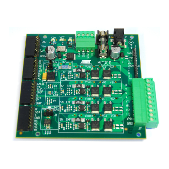
Figure 1-1. MC300 Motor control driver board.
=6A
max
8-bit
Microcontrollers
Application Note
Rev. 8124C-AVR-10/08
Advertisement
Table of Contents

Related Manuals for Atmel 8-bit AVR Microcontrollers AVR430: MC300


Summary of Contents for Atmel 8-bit AVR Microcontrollers AVR430: MC300
-
Page 1: Application Note
AVR430: MC300 Hardware User Guide Features 8-bit • General-purpose power stage for DC and stepper motors Microcontrollers • Modular system with 2,54mm pin header connector for device boards • Four half-bridges with independent control of high and low side • Onboard voltage regulators for device board (5/3,3V) and Hall sensors (5V) •... -
Page 2: Hardware Overview
2 Hardware overview Please refer to schematics, layout and BOM available at http://www.atmel.com. The MC300 motor control driver board is a power stage board intended for driving BLDC and stepper motors. It has four half-bridges with independent control of high and low sides. - Page 3 AVR430 2.2 Connections Figure 2-1. MC300 with device board, connector details and prototype board fitted. 2.2.1 Device board connector The MC300 driver board can directly connect to an AVR device board. This is accomplished by a horizontal female 0.1” pin header connector located on the left side of the board, shown in Figure 2-1.
- Page 4 Figure 2-2. Device board connector mechanical specification and schematics. 2.3 Jumpers Refer to component floorplan for location of jumpers. Table 2-1. Jumpers and their functions. Designator Use and settings Selects voltage source to Hall sensors (VHa) J1 open – VHa not connected J1 pin 2 &...
- Page 5 AVR430 Table 2-2. MC300 device board connector signal description. Located Name Direction Description J9p1 J9p2 System ground (Vin/VCC) J9p3 J9p4 Output Input power Vin (10-20V) J9p5 Output J9p6 Output Regulated power Vcc (3.3V/5V) J9p7 Output J9p8 System ground (Vin/VCC) J11p1 Input Phase U Highside control input J11p2...
-
Page 6: Pcb Layout
3 PCB 3.1 PCB Layout The MC300 is organized as shown in Figure 3-1. Most signals, important components and jumper information are written on the silk screen. For individual component placement refer to the component floorplan. Figure 3-1. MC300 PCB layout. In Figure 3-1 the following areas are marked: 1. - Page 7 ‘ShCom’. Filters/dividers for Vm, ShCom and Vn are found on the left of the phase areas. 3.2 Schematics, component floorplan and bill of materials The schematics, component floorplan and bill of materials (BOM) for MC300 are found as separate PDF files distributed with this application note, they can be downloaded from http://www.atmel.com. 8124C-AVR-10/08...
-
Page 8: Detailed Description
4 Detailed description 4.1 Power The MC300 has two power circuits. Vin for powering driver ICs and voltage regulators, and Vmotor (Vm) for powering the output stage (MOSFETs). The separate power supply for the motor, Vm, allows the use of motor voltages outside the voltage range of the driver ICs. - Page 9 AVR430 4.1.4 Hall sensors VHall (VHa) is available on J7 as power source for Hall sensors, typically found on BLDC motors. With J1 VHa can be connected to Vcc or to a 5V regulator (U2). A separate 5V regulator for the Hall sensors is included so Vcc can be 3,3V while using Hall sensors, since most Hall sensors will not work on 3,3V.
- Page 10 4.3 Shunts The board is shipped with a common shunt resistor (ShCom - R62) of 0,050 ohm and the four phase shunt resistors are zero ohm resistors, shown in Figure 4-3. This allows for measurement of the total current going to ground via all half bridges. Figure 4-3.
- Page 11 AVR430 4.4 Back-EMF For sensorless applications, the driving logic uses back EMF from the motor’s phases to keep track of the motor position. To observe the back EMF from a phase, the phase is left floating, i.e. with the high or low side MOS not powered, and the voltage on the phase is read.
- Page 12 4.5 Upgrading the MC300 As the board is shipped, its limitations are Vm =40V and Im =6A. These limits can be increased by replacing the relevant components (not included). 4.5.1 Voltage limitations If a Vm higher than 40V is required, then some components must be changed on the board.
- Page 13 BEEN ADVISED OF THE POSSIBILITY OF SUCH DAMAGES. Atmel makes no representations or warranties with respect to the accuracy or completeness of the contents of this document and reserves the right to make changes to specifications and product descriptions at any time without notice. Atmel does not make any commitment to update the information contained herein.
Need help?
Do you have a question about the 8-bit AVR Microcontrollers AVR430: MC300 and is the answer not in the manual?
Questions and answers