
Related Manuals for Atmel ATSAMD21BLDC24V-STK


Summary of Contents for Atmel ATSAMD21BLDC24V-STK
- Page 1 SMART ARM-based Motor Control Kit ATSAMD21BLDC24V-STK USER GUIDE Atmel-42681A-SMART-ARM-based-Motor-Control-Kit_User Guide-02/2016...
-
Page 2: Table Of Contents
Table of Contents 1. Atmel Low Voltage Motor Control Starter Kit............. 3 1.1. ATSAMD21BLDC24V-STK Features....................3 1.2. ATSAMD21BLDC24V-STK Kit Content..................4 1.3. Design Documentation and Relevant Links................. 5 2. Getting Started with ATSAMD21BLDC24V-STK............6 3. ATSAMD21BLDC24V-STK Hardware..............12 3.1. ATSAMD21BLDC24V-STK MCU Board..................12 3.2. -
Page 3: Atmel Low Voltage Motor Control Starter Kit
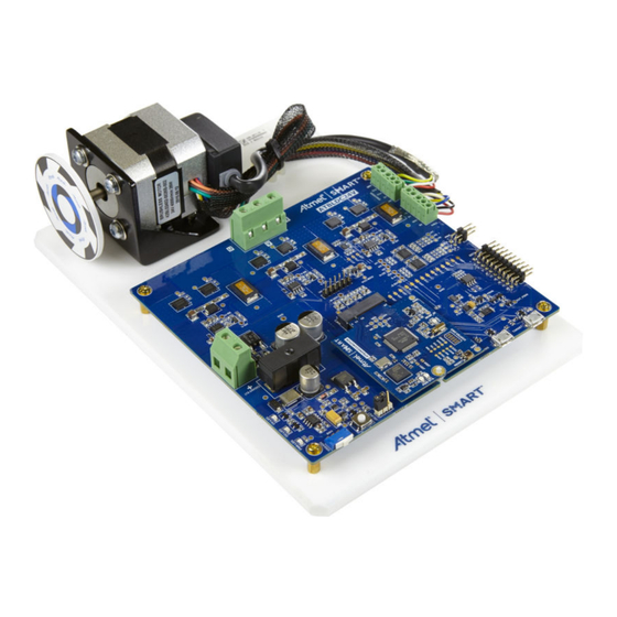
Hall and Encoder interface, fault protection circuits, etc. The ATSAMD21MOTOR MCU card is plugged into the driver board and has an on-board debugger. Supported by the Atmel studio integrated development platform, the kit provides easy access to the features of ATSAMD21J18A MCU and explains how to integrate the device in a custom motor control application. -
Page 4: Atsamd21Bldc24V-Stk Kit Content
Atmel studio plug-and-use support using unique ID device 1.2. ATSAMD21BLDC24V-STK Kit Content ATSAMD21BLDC24V-STK Kit contains the PCBs, BLDC motor, power adaptor and USB cable to get started and running the motor in the kit. The kit contains the following items: AT24VBLDC driver board. -
Page 5: Design Documentation And Relevant Links
- Atmel Xplained Pro is a series of small-sized and easy-to-use evaluation kits for Atmel microcontrollers and other Atmel products. It consists of a series of low-cost MCU boards for evaluation and demonstration of features and capabilities of different MCU families. -
Page 6: Getting Started With Atsamd21Bldc24V-Stk
Getting Started with ATSAMD21BLDC24V-STK This chapetr is a step-by-step guide to get started with the SAMD21BLDC24V-STK. SAMD21BLDC24V-STK kit contains a fully assembled chassis and 24VDC power adaptor. Connect the power adaptor to the “SUPPLY-IN connector”. Connect white color cable to + PIN. - Page 7 Figure 2-2. Data Visualizer Connect Window Click "Connect". The orange LED in the MCU board shall now blink. The Data Visualizer default window will pop up once the connection is made. All the fields shall show default values. Atmel ATSAMD21BLDC24V-STK [USER GUIDE] Atmel-42681A-SMART-ARM-based-Motor-Control-Kit_User Guide-02/2016...
- Page 8 Figure 2-3. Data Visualizer Start Window 10. Click on "Start" to turn the motor ON with default values. Atmel ATSAMD21BLDC24V-STK [USER GUIDE] Atmel-42681A-SMART-ARM-based-Motor-Control-Kit_User Guide-02/2016...
- Page 9 Figure 2-4. Data Visualizer "Start Motor" Window 11. Change the value in a field and press "Enter". For instance, to change the motor speed, type in the desired speed within the motor's rating and press "Enter". Atmel ATSAMD21BLDC24V-STK [USER GUIDE] Atmel-42681A-SMART-ARM-based-Motor-Control-Kit_User Guide-02/2016...
- Page 10 Figure 2-5. Data Visualizer "Change Parameter" 12. Stop the Motor by clicking the "Stop" button. 13. To change direction of rotation after "Stop", choose "CCW" in radio button and click "Start". Atmel ATSAMD21BLDC24V-STK [USER GUIDE] Atmel-42681A-SMART-ARM-based-Motor-Control-Kit_User Guide-02/2016...
- Page 11 Figure 2-6. Data Visualizer "Change Direction" 14. Adjust the graph by checking "Automatically fit Y". Atmel ATSAMD21BLDC24V-STK [USER GUIDE] Atmel-42681A-SMART-ARM-based-Motor-Control-Kit_User Guide-02/2016...
-
Page 12: Atsamd21Bldc24V-Stk Hardware
MCU board (MCU card) contains the MCU, clock circuit, and debug circuit. The MCU card is inserted into the 67-pin NGFF standard interface on the driver board. The ATSAMD21BLDC24V-STK comes with an ATSAMD21J18A MCU card. 3.1. -
Page 13: Atsamd21Bldc24V-Stk Driver Board
EDBG. SERCOM4 of the ATSAMD21J18A connected to the EDBG device support DGI SPI interface and uses Atmel ADP protocol. The MCU SERCOM4 is also connected to the UART channel of the EDBG through a pair of "normally open"... - Page 14 XPRO interface header, and UID chip circuits are the other features included in the driver board hardware. The figure below shows the main components and block diagram of driver board. Figure 3-3. ATSAMD21BLDC24V-STK Driver Board PCB Atmel ATSAMD21BLDC24V-STK [USER GUIDE]...
- Page 15 Figure 3-4. ATSAMD21BLDC24V-STK Block Diagram 3.2.1. Half-bridge FET Driver The half-bridge circuit is based on the NTMFS5C646NL N-channel Power MOSFET. Each half-bridge is driven by the NCP5106A gate driver. The gate driver takes two independent PWM inputs from the MCU and uses bootstrap technique to drive the high side Power MOSFET in the half-bridge. The bootstrap capacitor is tied between PIN5 and PIN8 of the NCP5106 through a resistor.
- Page 16 The driver board has multiple power supply selection options. Automatic supply input selection is similar to the Atmel Xplained Pro hardware. The block diagram shows how to use the SW1 user switch and the jumper available on the PCB to select the MCU voltage supply.
- Page 17 FET driver. The OVP circuit is shown in the figure below. Sense voltage is determined by the zener diode (D7) voltage (28V) and R-network R117 and R118. Vgs (threshold) of Q8A is typically 2V. Atmel ATSAMD21BLDC24V-STK [USER GUIDE] Atmel-42681A-SMART-ARM-based-Motor-Control-Kit_User Guide-02/2016...
- Page 18 Hall Sensor Interface The Hall sensor interface uses NTS0104 level translator. The interface is tested with motors with open drain and push pull type Hall sensor output. The LDO motor supplied with ATSAMD21BLDC24V-STK has open drain Hall sensor output type.
- Page 19 The encoder sensor interface uses a NTS0104 level translator. The interface is tested with motors with open drain and push pull type encoder sensor output. The LDO motor supplied with ATSAMD21BLDC24V-STK has open drain output type. 3.2.9. Atmel Xplained PRO Interface The Xplained PRO compatible header has a 20-pin EXT1 connector and a 4-pin power connector.
- Page 20 The UID chip is a unique ID chip used by the EDBG interface to enable automatic board identification in Atmel Studio. When the motor control evaluation board is connected to the USB port the Atmel studio recognizes it and load the necessary software and documentation.
- Page 21 Figure 3-11. Debug Test Points on the Driver Board 3.2.15. Motor Specification Specification and wiring for the motor are given in the figure below. Atmel ATSAMD21BLDC24V-STK [USER GUIDE] Atmel-42681A-SMART-ARM-based-Motor-Control-Kit_User Guide-02/2016...
- Page 22 Figure 3-12. Motor Specification Atmel ATSAMD21BLDC24V-STK [USER GUIDE] Atmel-42681A-SMART-ARM-based-Motor-Control-Kit_User Guide-02/2016...
-
Page 23: Atsamd21Bldc24V-Stk Mcu-Driver Interface
3.3. ATSAMD21BLDC24V-STK MCU-driver Interface Atmel low voltage motor control solution support plugable MCU cards. The MCU card and driver interface is a standard 67-pin interface as given in table below. Table 3-5. MCU-driver Interface Pin-out INTERFACE NAME DRIVER BOARD SAMD21J18A PIN... - Page 24 PB07 AIN1(AC1) HALL1 HALL1 PA03 EXTINT3 HALL2 HALL2 PA18 EXTINT2 HALL3 HALL3 PA28 EXTINT8 HALL TRX OE HALL_TRX_OE PB11 ENCODER_A ENCODER_A PB09 EXTINT9 ENCODER_B ENCODER_B PB10 EXTINT10 ENCODER_Z ENCODER_Z PB23 EXTINT7 ENCODER_EN ENCODER_EN PB22 Atmel ATSAMD21BLDC24V-STK [USER GUIDE] Atmel-42681A-SMART-ARM-based-Motor-Control-Kit_User Guide-02/2016...
- Page 25 3V3 SUPPLY for MCU VCC_P VCC_TARGET_P3V3 3V3 SUPPLY for MCU VCC_P VCC_TARGET_P3V3 Atmel ATSAMD21BLDC24V-STK [USER GUIDE] Atmel-42681A-SMART-ARM-based-Motor-Control-Kit_User Guide-02/2016...
-
Page 26: Hardware Revision History And Known Issues
4.1. Identifying Product ID and Revision The revision and product identifier of ATSAMD21BLDC24V-STK can be found by looking at the sticker on the bottom side of the PCB. The identifier and revision are printed in plain text as A09-nnnn\rr, where nnnn is the identifier and rr is the revision. -
Page 27: Product Compliance
Product Compliance RoHS and WEEE The Atmel ATSAMD21BLDC24V-STK and its accessories are manufactured in accordance to both the RoHS Directive (2002/95/EC) and the WEEE Directive (2002/96/EC). CE and FCC The Atmel ATSAMD21BLDC24V-STK unit has been tested in accordance to the essential requirements and other relevant provisions of Directives: •... -
Page 28: Revision History
Revision History Doc. Rev. Date Description 42681A 02/2016 Initial document release. Atmel ATSAMD21BLDC24V-STK [USER GUIDE] Atmel-42681A-SMART-ARM-based-Motor-Control-Kit_User Guide-02/2016... - Page 29 DISCLAIMER: The information in this document is provided in connection with Atmel products. No license, express or implied, by estoppel or otherwise, to any intellectual property right is granted by this document or in connection with the sale of Atmel products. EXCEPT AS SET FORTH IN THE ATMEL TERMS AND...
- Page 30 Mouser Electronics Authorized Distributor Click to View Pricing, Inventory, Delivery & Lifecycle Information: Atmel ATSAMD21BLDC24V-STK...
Need help?
Do you have a question about the ATSAMD21BLDC24V-STK and is the answer not in the manual?
Questions and answers