Table of Contents
Advertisement
Quick Links
Atmel AVR2016: RZRAVEN Hardware User's Guide
Features
•
Development kit for the Atmel
microcontroller
•
CE, ETSI and FCC approved
•
LCD module (Atmel AVRRAVEN):
•
AT86RF230 radio transceiver with high gain PCB antenna
•
Dual AVR microcontrollers
•
Dynamic speaker and microphone
•
Atmel Serial Dataflash
•
User I/O section:
•
USART
•
GPIO
•
Relay Driver
•
Powered by battery or external supply:
•
5V to 12V external supply
•
USB module (Atmel RZUSBSTICK):
•
AT86RF230 radio transceiver with miniature PCB antenna
•
AVR microcontroller with integrated Full Speed USB interface
•
External memory interface
Introduction
The Atmel RZRAVEN is a development kit for the AT86RF230 radio transceiver and
the AVR microcontroller. It serves as a versatile and professional platform for
developing and debugging a wide range of RF applications; spanning from: simple
point-to-point communication through full blown sensor networks with numerous
nodes running complex communication stacks. On top of this, the kit provides a nice
human interface, which spans from PC connectivity, through LCD and audio input
and output.
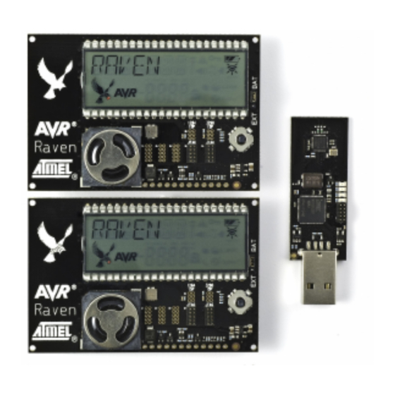
Figure 1.
The RZRAVEN kit modules.
APPLICATION NOTE
8-bit Atmel Microcontrollers
®
AT86RF230 radio transceiver and Atmel AVR
®
®
8117E−AVR−07/12
Advertisement
Table of Contents

Subscribe to Our Youtube Channel
Related Manuals for Atmel AVR2016


Summary of Contents for Atmel AVR2016
-
Page 1: Application Note
External memory interface Introduction The Atmel RZRAVEN is a development kit for the AT86RF230 radio transceiver and the AVR microcontroller. It serves as a versatile and professional platform for developing and debugging a wide range of RF applications; spanning from: simple point-to-point communication through full blown sensor networks with numerous nodes running complex communication stacks. -
Page 2: Table Of Contents
Compliance Statement (Part 15.19) ..........24 F.1.3 Warning (Part 15.21)................. 24 F.1.4 Compliance Statement (Part 15.105(b)) ........... 24 F.1.5 FCC IDs ................... 24 Atmel AVR2016: RZRAVEN Hardware User’s Guide [APPLICATION NOTE] 8117E−AVR−07/12... -
Page 3: General
General The Atmel RZRAVEN kit is built from one Atmel RZUSBSTICK module and two AVRRAVEN modules. See Figure 1-1 Figure 1-4 for further details. The complete schematics and Gerber files are available from the compressed archive accompanying this application note. -
Page 4: The Atmel Avrraven Module
The Atmel AVRRAVEN module Figure 2-1. AVRRAVEN overview. The AVRRAVEN hardware is based on two microcontrollers and one radio transceiver chip. The Atmel ATmega3290P handles the sensors and the user interface and the Atmel ATmega1284P handles the Atmel AT86RF230 radio transceiver and the RF protocol stacks. -
Page 5: Atmel Avr Microcontrollers
Antenna description The antenna on the AVRRAVEN is a 100Ω loop antenna with a net peak gain of about 5dB. The LCD found on the AVRRAVEN module is a full custom 160-segment display tailored for the Atmel RZRAVEN kit (See Figure 2-2 for a quick reference). -
Page 6: Microphone
Microphone The Atmel AVRRAVEN’s microphone is connected to the Atmel ATmega3290P ADC channel 0. The signal is amplified and low-pass filtered. Pulling PORTE7 low activates the microphone circuit. Serial Dataflash A 16Mb Atmel Serial Dataflash (AT45DB161D) is connected to the ATmega3290P’s Serial Peripheral Interface (SPI). -
Page 7: Interfaces
An onboard voltage regulator makes it possible to run power the AVRRAVEN from a 5V to 12V DC source. The external voltage is applied to the two leftmost pins in the user I/O area (J401). The Atmel ATmega3290P’s ADC channel 2 is connected to a voltage divider and the external voltage supply interface. -
Page 8: 2.12.1 Programming Interface
Connected to internal 0V Care should be taken when connecting to the Atmel AVRRAVEN’s interfaces, since there is no protection circuitry provided. Damage to the MCUs or other circuits may be the result of ESD spark, short circuits, polarity or over-voltage faults. -
Page 9: 2.12.2 Relay Interface
ISP programming can be performed by connecting an ISP enabled Atmel AVR programming tool to the pin header J302 ® (ATmega3290P) and J205 (ATmega1284P). AVR tools like Atmel STK 500, AVRISP mkII and JTAGICE mkII can be used for this. -
Page 10: The Atmel Avr Rzusbstick Module
PCB Connection Comment ATmega1284P Port Pin PCB Connection Comment External power J201-10 Connectec to J401-1 J202-10 J203-10 J201-9 Connected to J401-2 J202-9 J203-9 The Atmel AVR RZUSBSTICK Module Figure 3-1. RZUSBSTICK overview. Atmel AVR2016: RZRAVEN Hardware User’s Guide [APPLICATION NOTE] 8117E−AVR−07/12... -
Page 11: Avr Microcontroller
Appendix D for the complete AVR RZUSBSTICK schematics. AVR Microcontroller The Atmel AT90USB1287 is a device in the family of AVRs with a low and full speed USB macro with device, host and On-the-go (OTG) capabilities. Atmel Radio Transceiver The AT86RF230 is a 2.4GHz radio transceiver that is tailored for a wide range of wireless applications. Low power consumption and market leading RF performance makes it an excellent choice for virtually any type of networking device. -
Page 12: External Memory Interface
Serial Interface The USART on the Atmel AT90USB1287 is routed to J4 on the Atmel RZRAVEN’s backside. J4 is implemented as three large pads (RX-TX-GND) where the user can solder in wires and route the signal to his or her preference. The RX-TX signals are TTL level, so an external level converter must be connected if RS232 levels are necessary. -
Page 13: Appendix A. Atmel Avrraven Schematics
Atmel AVRRAVEN Schematics Appendix A. Atmel AVR2016: RZRAVEN Hardware User’s Guide [APPLICATION NOTE] 8117E−AVR−07/12... - Page 14 Atmel AVR2016: RZRAVEN Hardware User’s Guide [APPLICATION NOTE] 8117E−AVR−07/12...
- Page 15 Atmel AVR2016: RZRAVEN Hardware User’s Guide [APPLICATION NOTE] 8117E−AVR−07/12...
- Page 16 Atmel AVR2016: RZRAVEN Hardware User’s Guide [APPLICATION NOTE] 8117E−AVR−07/12...
- Page 17 Atmel AVR2016: RZRAVEN Hardware User’s Guide [APPLICATION NOTE] 8117E−AVR−07/12...
-
Page 18: Appendix B. Atmel Avrraven Bill Of Materials
L202, L203 RF Inductor, 2.7nH, 0,17ohm, 300mA, 0402 Johanson L-07C2N7SV6T Technology D401, D403, D408 Dual Schottky diode BAT54SWFILM D501 Dual Schottky diode Philips 1PS70SB15 D404 Bidirectional Transient suppression diode, SM6T12CA 600W Atmel AVR2016: RZRAVEN Hardware User’s Guide [APPLICATION NOTE] 8117E−AVR−07/12... - Page 19 1x3 pin header, 2 mm pitch, THM SAMTEC TMM-103-01-L-S JS501 Jumper cap for 2.00mm pinheader SAMTEC 2SN-BK-G BT501, BT502 LR44 coin-cell battery D301 LED, Red, SMD 0603 Lumex SML-LX0603SRW-TR U302 AVRRAVEN LCD Orient Display 0710091B Atmel AVR2016: RZRAVEN Hardware User’s Guide [APPLICATION NOTE] 8117E−AVR−07/12...
-
Page 20: Appendix C. Atmel Avrraven Lcd
Atmel AVRRAVEN LCD Appendix C. Figure 3-4. AVRRAVEN Segments. Atmel AVR2016: RZRAVEN Hardware User’s Guide [APPLICATION NOTE] 8117E−AVR−07/12... - Page 21 RAVEN+AVR MOON Z_ZIGBEE COM0 SEG23 SEG22 SEG21 SEG20 SEG19 SEG18 SEG17 SEG16 LCDDR2 ATT! SEG15 SEG14 SEG13 SEG12 SEG11 SEG10 SEG9 SEG8 LCDDR1 SEG7 SEG6 SEG5 SEG4 SEG3 SEG2 SEG1 SEG0 LCDDR0 Atmel AVR2016: RZRAVEN Hardware User’s Guide [APPLICATION NOTE] 8117E−AVR−07/12...
-
Page 22: Appendix D. Atmel Rzusbstick Schematics
Atmel RZUSBSTICK Schematics Appendix D. Atmel AVR2016: RZRAVEN Hardware User’s Guide [APPLICATION NOTE] 8117E−AVR−07/12... -
Page 23: Appendix E. Atmel Rzusbstick Bill Of Materials
Golledge GSX-752B/551EF 8MHz PCB1 RZUSBStick PCB ATMEL A08-0384 USB type A plug, SMD SAMTEC USB-AM-S-F-B-SM1-R LED, Red Everlight EL17-21USRC LED, Green Everlight EL17-21SYGC LED, Yellow Everlight EL17-21UYC/A2 LED, Blue Everlight EL17-21UBC Atmel AVR2016: RZRAVEN Hardware User’s Guide [APPLICATION NOTE] 8117E−AVR−07/12... -
Page 24: Appendix F. Federal Communications Commission (Fcc) Statement24
These devices must accept any interference received including interference that may cause undesired operation. F.1.3 Warning (Part 15.21) Changes or modifications not expressly approved by Atmel Norway could void the user’s authority to operate the equipment. F.1.4 Compliance Statement (Part 15.105(b)) This equipment has been tested and found to comply with the limits for a Class B digital device, pursuant to Part 15 of the FCC Rules. - Page 25 Atmel Corporation or its subsidiaries. Other terms and product names may be trademarks of others. Disclaimer: The information in this document is provided in connection with Atmel products. No license, express or implied, by estoppel or otherwise, to any intellectual property right is granted by this document or in connection with the sale of Atmel products.
Need help?
Do you have a question about the AVR2016 and is the answer not in the manual?
Questions and answers