Table of Contents
Advertisement
Service
This manual is to be used by qualified appliance
technicians only. Maytag does not assume any
responsibility for property damage or personal
injury for improper service procedures done by
an unqualified person.
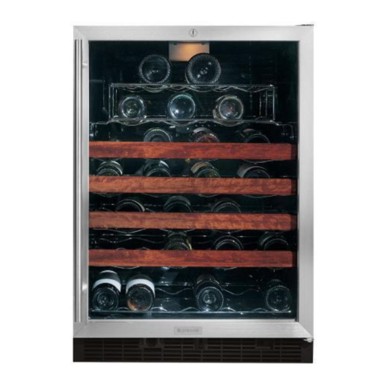
Wine Cellar
Under Counter
Refrigerator
This Base Manual covers general information
Refer to individual Technical Sheet
for information on specific models
This manual includes, but is
not limited to the following:
Jenn-Air
JWC2450ARB
JWC2450ARW
JWC2450ARS
JWC2450ACX
JUC2450ARB
JUC2450ARW
JUC2450ARS
JUC2450ACX
16022323
July 2003
Advertisement
Chapters
Table of Contents
Troubleshooting

Subscribe to Our Youtube Channel
Related Manuals for Jenn-Air JWC2450ARB


Summary of Contents for Jenn-Air JWC2450ARB
- Page 1 Service This manual is to be used by qualified appliance technicians only. Maytag does not assume any This Base Manual covers general information responsibility for property damage or personal injury for improper service procedures done by Refer to individual Technical Sheet an unqualified person.
-
Page 2: Important Information
Important Notices for Servicers and Consumers Maytag will not be responsible for personal injury or property damage from improper service procedures. Pride and workmanship go into every product to provide our customers with quality products. It is possible, however, that during its lifetime a product may require service. -
Page 3: Table Of Contents
Condenser Fan Removal ........15 Evaporator Thermistor Removal ......15 Evaporator Thermistor Installation ......15 Wiring Diagram ............16 Appendix A Wine Cellar Owners Guide ........A-1 Appendix B Under Counter Refrigerator Owners Guide ..... B-1 16022323 Rev. 0 ©2003 Maytag Appliances Company... -
Page 4: Model Identification
Jenn-Air Model Identification Color W White B Black S Stainless X Accepts Panel Special Features Dimensions 24 Inches Wide Product WC Wine Cellar Under Counter Refrigerator Jenn-Air 16022323 Rev. 0 ©2003 Maytag Appliances Company... -
Page 5: Component Testing
To avoid risk of electrical shock, personal injury, or death, disconnect electrical power source to unit, unless test procedures require power to be connected. Discharge capacitor through a resistor before attempting to service. Ensure all ground wires are connected before certifying unit as repaired and/or operational. 16022323 Rev. 0 ©2003 Maytag Appliances Company... - Page 6 To avoid risk of electrical shock, personal injury, or death, disconnect electrical power source to unit, unless test procedures require power to be connected. Discharge capacitor through a resistor before attempting to service. Ensure all ground wires are connected before certifying unit as repaired and/or operational. Component Description Test Procedures 16022323 Rev. 0 ©2003 Maytag Appliances Company...
-
Page 7: Compressor
If compressor runs after recovery but would not run when direct wired before recover, a restriction in sealed system is indicated. • If compressor does not run when wired direct after recovery, replace 16022323 Rev. 0 ©2003 Maytag Appliances Company faulty compressor. - Page 8 To avoid risk of electrical shock, personal injury, or death, disconnect electrical power source to unit, unless test procedures require power to be connected. Discharge capacitor through a resistor before attempting to service. Ensure all ground wires are connected before certifying unit as repaired and/or operational. 16022323 Rev. 0 ©2003 Maytag Appliances Company...
-
Page 9: Condenser
Remove any lint or other accumulation, that would restrict normal air movement through condenser. From condenser the refrigerant flows into the drier to evaporator and into compressor through suction line. 16022323 Rev. 0 ©2003 Maytag Appliances Company... -
Page 10: Ptc Relay
Cabinet light Single pole, single throw switch Check resistant across terminals. switch completes circuit for light when door is Switch arm depressed open. “NO” terminals Open Switch arm up “NO” terminals Closed 16022323 Rev. 0 ©2003 Maytag Appliances Company... -
Page 11: Drier
Do not use high pressure compressed gases in refrigeration tube soldered to suction line. systems without a reliable pressure regulator and pressure relief valve in the lines. Refrigerant gas is pulled through suction line by compressor, completing refrigeration cycle. 16022323 Rev. 0 ©2003 Maytag Appliances Company... -
Page 12: Thermistor
Temperature sensing bulb changes Check resistance vs. temperature. See chart: resistance with change of temperature. Resistance vs. Temperature Chart RESISTANCE TEMPERATURE C TEMPERATURE F (KOHMS) 11.350 8.918 6.700 5.630 4.520 3.652 2.970 2.430 2.000 16022323 Rev. 0 ©2003 Maytag Appliances Company... -
Page 13: Troubleshooting
The mounting be located at mid point of bracket should be located at the mid-point of each 3- each 3-inch leg. Both legs secured under bracket. inch leg. Both legs secured under bracket. 16022323 Rev. 0 ©2003 Maytag Appliances Company... - Page 14 Pressure does not equalize quickly when the compressor is turned off. 16022323 Rev. 0 ©2003 Maytag Appliances Company...
- Page 15 (permagum) to wiring or thermostat eliminate air leaks. capillary tubes enter cabinet interior. Door gasket torn or has Replace gasket if stiff, torn lost magnetism. or has stiff, torn or weak magnetism. 16022323 Rev. 0 ©2003 Maytag Appliances Company...
- Page 16 Light activation switch. Failed light activation Replace light activation switch. switch. 16022323 Rev. 0 ©2003 Maytag Appliances Company...
-
Page 17: Troubleshooting
This is light activation switch and intended for glass door confirming light goes out. viewing with door closed. Over-ride switch Failed over-ride switch. Replace over-ride switch operation. 16022323 Rev. 0 ©2003 Maytag Appliances Company... -
Page 18: Disassembly Procedures
Be sure to check for leaks and evacuate to 50 microns. the evaporator. Be sure to also reinstall the suction line and tubing harness insulation tubes. 6. Reinstall PTC starter and wire according to wire diagram. 7. Reinstall compressor cap. 16022323 Rev. 0 ©2003 Maytag Appliances Company... -
Page 19: Condenser Removal
6. Disconnect the neutral white wire lead (black ribbed wire) at the terminal block and the hot wire lead (black smooth wire) at the electronic control. 7. Remove the condenser fan. Condenser Fan Installation: Reverse the removal procedure for installation. 16022323 Rev. 0 ©2003 Maytag Appliances Company... -
Page 20: Wiring Diagram
WHITE WITH YELLOW STRIPE OV'LD WHITE P.T.C. BLACK CAP. RELAY COMPRESSOR FAN SWITCH WHITE BLACK LIGHT SWITCH TRANSFORMER INTERIOR FAN ON/OFF BLUE SWITCH BLACK BLUE WHITE LIGHT 41006543 REV. E OPTIONAL FEATURE DIMMER SWITCH 16022323 Rev. 0 ©2003 Maytag Appliances Company... - Page 21 Appendix A 16022323 Rev. 0 A -1 ©2003 Maytag Appliances Company...
- Page 22 E N N I N E H I L L E R ’ WN E R U I DE A B L E O F O N T E N T S Introduction................1 Safety ..................2 Installation.................3–11 Operation................12 Features ..................13 Care and Cleaning..............14 Before Calling for Service ..........15 Warranty..................17 Guide du propriétaire ............18...
-
Page 23: Introduction
Introduction Congratulations on the purchase of a Jenn-Air Before Calling for Service . . . Refrigerated Wine Chiller. If something seems unusual, please check the “Before We appreciate your purchase decision and feel Calling For Service” section, which is designed to help confident you will be happy with this appliance for solve basic problems before calling a servicer. -
Page 24: Important Safety Instructions
Important Safety Instructions WARNING WARNING • When using your appliance, always follow basic • This appliance is designed to operate on a normal precautions. 115 volt, 15 amp, 60 cycle line. There should be a separate, grounded circuit serving this appliance only. -
Page 25: Installation
Installation Materials Needed Cabinet Cutout Dimensions • " Allen wrench ⁄ • " socket ⁄ • Phillips screwdriver • Putty knife • Carpenter’s level Select Location The wine chiller was designed to be installed under the counter. Its proper location will ensure peak performance. -
Page 26: Leveling Legs
Dimensions Leveling Legs Install leveling legs (located in literature pack): Front • With at least two people, tip wine chiller backwards until there is approximately 12" (31 cm) of clearance between the floor and the wine chiller. min. 34" (86.4 cm) max. - Page 27 Installation , cont. Reversing the Glass Door Lock cam Lock body Phillips screw WARNING • To avoid electrical shock which can cause personal Lock injury or death, disconnect power to the wine chiller extension before reversing the door. Glass The wine chiller door can have a left or right hand door Door swing.
- Page 28 13. Relocate the light striker plate to the opposite end of holes in the glass door and align these holes with the door, lining up the two holes in the striker plate, the threaded weld nuts in the overlay. Use the ten with the two holes at the opposite center of the screws removed in step 9 to resecure the stainless door.
- Page 29 Installation , cont. Prepare the Custom Door Assemble Door Hinge Brackets Wood Frame NOTE: Skip this step if hinges are already attached. 1. Attach the top and bottom door hinges to the door Custom Handle with the 10-32 machine screws and a "...
- Page 30 Lock Hole Detail Center Line " ⁄ (59.5 cm) Thickness: " to " ⁄ ⁄ (1.6 to 1.9 cm) " ⁄ (29.8 cm) Mounting surface (non-face) side of wood frame " (1.2 cm) ⁄ diameter through hole " (1.2 cm) ⁄...
- Page 31 Installation , cont. Attach the Wood Panel to the Wine Bottom Hinge Corner Chiller Door WARNING • To avoid electrical shock which can cause severe Wood frame personal injury or death, disconnect power to wine chiller before installing wood frame. CAUTION Door hinge •...
- Page 32 2. Install the supplied lock body into the wood panel. 8. Reinstall the door gasket by pressing into door The lock and key assembly is supplied with your channel. Make certain the corners are inserted wine chiller. Secure the lock body by using the fully.
-
Page 33: Wine Racks
Installation , cont. Wine Racks CAUTION • Do not attempt to remove a rack while it has wine The wine chiller features slide out racks at the mid and bottles stored. Always empty the rack prior to lower level. The upper two racks are fixed. removing it from the cabinet. -
Page 34: Operation
Operation 1. Setting the Control: Loading Tips and Suggestions: The available settings of 1 through 7 provide a 1. As with most refrigeration products, there is a temperature range in the wine chiller from the low slight temperature variance at different locations forties to the mid sixties. -
Page 35: Features
Features • Adjustable Temperature Control: The temperature control is adjustable from the low forties to the mid sixties. The temperature range allows flexibility for storage temperature preferences and accommodates storage of a variety of red, white and sparkling wines. • Interior Light: The light control knob is located on the lower right front of the wine chiller, in the toe kick area. -
Page 36: Care And Cleaning
Care and Cleaning Cleaning Light Bulb Replacement WARNING WARNING • To avoid electrical shock which can cause severe • To avoid electrical shock which can cause severe personal injury or death, disconnect power to the personal injury or death, disconnect power to the wine chiller before cleaning. -
Page 37: Before Calling For Service
Before Calling for Service Before calling for service check the troubleshooting table below. This table lists possible problems that you can remedy without difficulty to avoid an unnecessary service call. PROBLEM POSSIBLE CAUSE/SOLUTIONS Odor in wine chiller • Interior needs cleaning. Noisy operation •... - Page 38 Notes...
-
Page 39: Warranty
User’s guides, service manuals and parts information are available from Maytag Services , Jenn-Air Customer Assistance. Jenn-Air • 403 West Fourth Street North • P.O. Box 39 • Newton, Iowa 50208... - Page 40 Appendix B 16022323 Rev. 0 B -1 ©2003 Maytag Appliances Company...
- Page 41 E N N N D E R O U N T E R E F R I G E R A T O R ’ WN E R U I DE A B L E O F O N T E N T S Introduction................1 Safety ..................2 Installation ................3–7...
-
Page 42: Introduction
If you have These numbers are found on a data plate located on questions, write us (include your model number and the upper left side inside the refrigerator. phone number) or call: Maytag Services Model Number__________________________________ Attn: Jenn-Air CAIR ® Center P.O. - Page 43 Important Safety Instructions WARNING WARNING • When using your appliance, always follow basic • This appliance is designed to operate on a normal precautions. 115 volt, 15 amp, 60 cycle line. There should be a separate, grounded circuit serving this appliance only.
-
Page 44: Installation
Installation Materials Needed Cabinet Cutout Dimensions • " Allen wrench ⁄ • " socket ⁄ • Phillips screwdriver • Putty knife • Carpenter’s level Select Location The refrigerator was designed to be installed under the counter. Its proper location will ensure peak performance. -
Page 45: Level The Refrigerator
Dimensions Leveling Legs Front Install leveling legs (located in literature pack): • At least 2 people are needed to tip the refrigerator backwards until there is approximately 12" (30.5 cm) of clearance between the floor and the refrigerator. min. 34" Weldnut (86.4 cm) (each bottom... -
Page 46: Reversing The Door
Installation , cont. Reversing the Door • Using a Phillips screwdriver, remove the 6 screws that are attaching the liner to the door. The screw covers will rotate with the screws. WARNING • Rotate the door liner 180º and align the screw •... - Page 47 4. Reinstall the door by Installing the Custom Door Hinge locating it over the Panel (select models) bottom hinge pin and Top of pushing down and in. Refrigerator Reinstall the top WARNING Hinge hinge pin. Check the Bracket • To avoid electrical shock which can cause severe door for proper personal injury or death, disconnect power to alignment.
-
Page 48: Refrigerator Door
Installation , cont. Wood Screws Attach the Wood Panel to the Refrigerator Door 1. #8 pan head wood screws are recommended to properly secure the custom wood panel to the 1. Place the custom wood panel on a non-abrasive refrigerator door. surface, protected by towels or rugs, to avoid 2. -
Page 49: Operation
Operation Features 1. Setting the Control: Interior Light The temperature control knob is located at the The interior light makes it easy to view what is stored bottom front of the refrigerator, near the center of in the refrigerator. the grille. The light automatically comes on when the door is Initially turn the control opened. -
Page 50: Care And Cleaning
Care and Cleaning Cleaning Light Bulb Replacement WARNING WARNING • To avoid electrical shock which can cause severe • To avoid electrical shock which can cause severe personal injury or death, disconnect power to the personal injury or death, disconnect power to the refrigerator before cleaning. -
Page 51: Before Calling For Service
Before Calling for Service Before calling for service check the troubleshooting table below. This table lists possible problems that you can remedy without difficulty to avoid an unnecessary service call. PROBLEM POSSIBLE CAUSE/SOLUTIONS Odor in refrigerator • Interior needs cleaning. Noisy operation •... -
Page 52: Warranty
User’s guides, service manuals and parts information are available from Maytag Services , Jenn-Air Customer Assistance. Jenn-Air • 403 West Fourth Street North • P.O. Box 39 • Newton, Iowa 50208...
Need help?
Do you have a question about the JWC2450ARB and is the answer not in the manual?
Questions and answers