Table of Contents
Advertisement
Quick Links
Refer to the included CD-ROM for the German, French, Spanish and Italian "INSTRUCTION MANUAL".
Die "BEDIENUNGSANLEITUNG" in den Sprachen Deutsch, Französisch, Spanisch und Italienisch
finden Sie auf der beiliegenden CD-ROM.
Utilisez le CD-ROM fourni pour consulter le "MANUEL D'INSTRUCTIONS" en allemand, français,
espagnol et italien.
Consulte en el CD-ROM suministrado el "MANUAL DE INSTRUCCIONES" en alemán, francés, español e
italiano.
Per il "MANUALE DI ISTRUZIONI" in Tedesco, Francese, Spagnolo e Italiano, fare riferimento al CD-
ROM allegato.
CARD
CARD
MENU
RESET
EJECT
CARD
CARD
MENU
RESET
EJECT
Advertisement
Table of Contents

Related Manuals for Sanyo DSR-3716P


Summary of Contents for Sanyo DSR-3716P
- Page 1 CARD CARD MENU RESET EJECT CARD CARD MENU RESET EJECT Refer to the included CD-ROM for the German, French, Spanish and Italian “INSTRUCTION MANUAL”. Die “BEDIENUNGSANLEITUNG” in den Sprachen Deutsch, Französisch, Spanisch und Italienisch finden Sie auf der beiliegenden CD-ROM. Utilisez le CD-ROM fourni pour consulter le “MANUEL D’INSTRUCTIONS”...
- Page 2 To avoid electrical shock, do not open the cabinet. Refer servicing to qualified personnel only. If the power supply cord (AC power cord) of this appliance is damaged, it must be replaced. Return to a SANYO Authorised Service Centre for replacement of the cord. Location...
-
Page 3: Main Features
Searching within the archive area Searching for intruder motion using motion detection Copyright search This manual and software are copyrighted by Sanyo Two-level security lock function - lets you Electric Co., Ltd. restrict users for data and equipment Brand and product names used in this manual are the management. -
Page 4: Table Of Contents
Basic connections ........11 Notes on installation locations ....... 5 Connecting RS-485 terminals ...... 11 The hard disk and cooling fan are consumable Connecting SANYO protocol devices components........... 6 (Dome Cameras) .......... 13 Important recordings ........6 Connecting an amplifier ....... 13 Protection of the hard disk ...... - Page 5 1 INTERFACE SPECIFICATIONS ....111 3 MENU SETTING SEQUENCE ....121 RS-485 specifications ........ 111 INDEX .............. 123 SANYO protocol command table ....112 2 SPECIFICATIONS ........113 Specifications ..........113 Dimensions ..........114 Table of recording rate and times ....115 Table of recording rate settings ....
-
Page 6: Before Use
BEFORE USE Notes on handling the internal HDD Notes on replacing the HDD Be sure to follow the correct procedure when replacing the This digital video recorder uses an internal hard disk drive HDD. (HDD). HDDs that have been removed from their packing may Be sure to observe the following points carefully when not operate correctly if they are subjected to sudden operating, setting-up, or servicing the digital video... -
Page 7: The Hard Disk And Cooling Fan Are Consumable Components
Always perform test recording in advance to confirm whether the digital video recorder’s playback is normal. Note that Sanyo will accept no responsibility for losses occurring as a result of recording or playback problems caused by malfunction of this digital video recorder or any connected devices. -
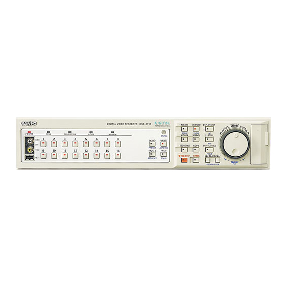
Page 8: Names And Functions Of Parts
NAMES AND FUNCTIONS OF PARTS DSR-3716P SHUTTLE MENU EXIT/OSD PLAY/STOP MENU ENTER POWER FULL ALARM FULL LOCK ALARM ZOOM SEARCH STILL FUNC. CARD AUDIO QUAD MULTI IRIS SEQUENCE COPY SHUTTLE HOLD PRESET AUTO PAN MON 2 PLUS FOCUS REC/STOP TIMER... - Page 9 NAMES AND FUNCTIONS OF PARTS DSR-3709P SHUTTLE MENU EXIT/OSD PLAY/STOP MENU ENTER POWER FULL ALARM FULL LOCK ALARM ZOOM SEARCH STILL FUNC. CARD CARD CARD AUDIO QUAD MULTI IRIS SEQUENCE COPY SHUTTLE HOLD AUTO PAN PRESET MON 2 PLUS FOCUS REC/STOP TIMER ALARM...
- Page 10 For recommended recordable drives, check the Sanyo 23. [ALARM] buttons ( P.31) homepage or ask at your local Sanyo dealer. When an [ALARM] button is pressed during playback or Sanyo website URL: still, the digital video recorder skips to the next earlier or http://www.sanyosecurity.com...
-
Page 11: Rear Panel
NAMES AND FUNCTIONS OF PARTS DSR-3716P (The number of terminals for the DSR-3709P may differ. For more details, see below.) AC IN ALARM IN C 1 2 3 4 5 6 7 8 9 10 11 12 13 14 15 16... -
Page 12: Installation And Connections
A separate power supply is required for operation of each camera. Basic connections The following diagram shows the connections for cameras, monitors, a microphone, and a PC. DSR-3716P System controller (sold separately) The DSR-3709P can be connected to nine cameras. VSP-8000/9000... - Page 13 INSTALLATION AND CONNECTIONS Connection RS-485 termination switch settings The digital video recorder supports both straight type and When connecting multiple devices, you must make crossed type connection cables. termination settings on both end devices. When using a straight type connection cable, connect the Set the RS-485 termination switch of both end devices RS-485 connector’s pin A to the pin A socket, or pin B to to ON.
-
Page 14: Connecting Sanyo Protocol Devices (Dome Cameras)
INSTALLATION AND CONNECTIONS Connecting SANYO protocol devices Connecting an amplifier (Dome Cameras) An amplifier is connected when using a microphone or external speakers with the digital video recorder. Turn off all devices and use a coaxial cable to connect the devices. -
Page 15: Operation
: Camera 3*: AUTO FOCUS SW 3 SW 19 : STILL In these cases, contact a Sanyo service center. : Camera 4*: SEQUENCE SW 20 : SEARCH SW 4 POWER... -
Page 16: Preparing For Use
PREPARING FOR USE (5) Picture quality display ( P.71) Operation display area Displays the quality of the video that can be recorded on the hard disk. Set to “EN” (Enhanced) by default. Whenever the power is turned on, the operation display Basic area will be shown at the top of the monitor screen. -
Page 17: Changing The Position Of The Operation Display Area
PREPARING FOR USE [MENU] button [EXIT/OSD] button Shuttle dial CARD CARD MENU RESET EJECT [REC/STOP] button Jog dial Changing the position of the Press the [MENU] button. operation display area The MENU indicator lights up and the <MAIN MENU> is displayed. -
Page 18: Setting The Time
PREPARING FOR USE Turn the shuttle dial clockwise, and Turn the shuttle dial clockwise. then turn the jog dial to select the The <LANGUAGE/LANGUE/SPRACHE/IDIOMA> screen desired language. is displayed. The set item flashes. <LANGUAGE/LANGUE/SPRACHE/IDIOMA> ENGLISH <REGL.LANGUE> <CLOCK SET> FRANCAIS 01-01-2004 THU 00:00:00 <REGL.HORLOGE>... -
Page 19: The Internal Hard Disk
PREPARING FOR USE [C] Archive area The internal hard disk Recording Recording method mode This area is used to store important <RECORDING AREA SET> TOTAL CAPACITY 82GB video data copied from the normal NORMAL RECORDING AREA 80 % recording area and/or alarm recording AREA FULL RESET ->... -
Page 20: Viewing Video From A Camera
VIEWING VIDEO FROM A CAMERA [MULTI] button [SEQUENCE] button CARD CARD MENU RESET EJECT [PLUS] button [CAMERA SELECT] buttons [MON2] button [QUAD] button Viewing on a full screen Viewing on quad screens Example: Selecting Camera 2 Images from multiple connected cameras can be displayed simultaneously. -
Page 21: Viewing On Multi Screens (9 Screens/ 16 Screens)
[CAMERA SELECT] button. Press [MULTI] button to switch from multi 6 screen display to multi 13 screen display. Operation can be performed solely with DSR-3716P. MULTI Press [PLUS] button to return to the previous display. The time required for updating differs for each image. -
Page 22: Viewing With Automatic Screen Selection
VIEWING VIDEO FROM A CAMERA Press the [SEQUENCE] button. Viewing with automatic screen selection The content of the split screen will automatically toggle between video from cameras No. 1 through No. 4 and video from cameras No. 5 through No. 8, No. 9 through Setting automatic full screen selection No. - Page 23 VIEWING VIDEO FROM A CAMERA Monitor 2 operation is not possible when a menu screen If the monitor 2 is not synchronized with the connected cameras, vertical picture instability may occur upon the is being displayed. switching of camera video. As the [EXIT/OSD] button is pressed, the operating display moves to a different location or is hidden in the same manner as the main monitor.
-
Page 24: Recording
RECORDING POWER indicator FULL indicator CARD CARD MENU RESET EJECT [REC/STOP] button [TIMER] button Normal recording Timer recording Use the following procedure to record the monitored video Use the following procedure to record the monitored video in the normal recording area. for a preset length of time in the normal recording area. -
Page 25: Alarm Recording
RECORDING POWER indicator [EXIT/OSD] button ALARM FULL indicator CARD CARD MENU RESET EJECT Alarm recording Counts the number 01-01-04 00:00:00 REC REPEAT EN A ALARM 0000 of alarms. Use the following procedure to automatically record alarm Values between video to the alarm recording area when an alarm signal is 0000 and 9999 can detected. -
Page 26: Pre-Alarm Recording
RECORDING Pre-alarm recording If an alarm is detected Pre-alarm recording is automatically ended and alarm Use the following procedure to record video from recording starts. immediately before occurrence of an alarm. “PRE” from the operation display area is replaced by “ALARM”, and “ALARM”... -
Page 27: Playback
PLAYBACK Use the following procedure to play video stored in the normal recording area (during normal or timer recording). POWER indicator [ZOOM] button [PLAY/STOP] button Normal Shuttle dial recording area CARD CARD Jog dial MENU RESET EJECT [QUAD] button [MULTI] button [STILL] button [CAMERA SELECT] buttons [SHUTTLE HOLD] button... -
Page 28: Changing The Playback Speed
PLAYBACK (2) Returning to normal playback. Changing the playback speed Press the [SHUTTLE HOLD] button to SHUTTLE HOLD turn off SHUTTLE HOLD indicator. Starting fast-forward or slow playback Turn the shuttle dial either clockwise or counter-clockwise to display “ ” in (1) Performing fast-forward. -
Page 29: Viewing Still Images
PLAYBACK In this way, move the zoom frame to enclose the area of Viewing still images video to be magnified. Press the [STILL] button during playback. The STILL indicator lights up and playback video is paused. The symbol “ ” appears in the operation display area. STILL 01-01-04 00:00:00 REPEAT EN A ALARM 0000... -
Page 30: Performing Frame Advance (Forward Or Reverse)
PLAYBACK Press the [QUAD] button. Performing frame advance (forward or reverse) Each time this button is pressed, the content of the split screen will toggle between video from cameras No. 1 Turn the jog dial clockwise or counter- through No. 4 and video from cameras No. 5 through No. clockwise while playback is paused. -
Page 31: Searching For Recorded Video
SEARCHING FOR RECORDED VIDEO Images stored in the normal recording area, alarm (1) ALARM SEARCH ( P.31) Lets you search and playback alarm video from the recording area or archive area can be located by recording list. searching and can then be played back. Use one of the following five search methods to locate the required video. -
Page 32: Alarm Search
SEARCHING FOR RECORDED VIDEO Turn the jog dial to select the video for Alarm search playback. A preview of the selected alarm video is displayed in the Use the following procedure to search and playback all preview screen. In this case, the video from the instant of video stored in the alarm recording area. -
Page 33: Alarm Thumbnail Search
SEARCHING FOR RECORDED VIDEO Turn the shuttle dial clockwise. Alarm thumbnail search The selected recording is played back in full screen mode. Use the following procedure to display all of the alarm recordings stored in the alarm recording area as thumbnails list. - Page 34 SEARCHING FOR RECORDED VIDEO Turn the shuttle dial clockwise. Turn the shuttle dial clockwise. After searching, the recording for the date and time The <TIME/DATE SEARCH> screen is displayed. settings is displayed in the preview screen. <TIME/DATE SEARCH> RECORDING TOP : 01-10-04 14:46 <TIME/DATE SEARCH>...
-
Page 35: Archive Area Search
SEARCHING FOR RECORDED VIDEO Turn the jog dial to select the video for Archive area search playback. The selected image is displayed on the preview screen. Use the following procedure to playback video that has been stored in the archive area. Press the [SEARCH] button while the digital video recorder is recording or stopped. - Page 36 SEARCHING FOR RECORDED VIDEO Turn the jog dial to select “MOTION Turn the shuttle dial clockwise, and DETECTION SEARCH”, and then turn then turn the jog dial to select a camera the shuttle dial clockwise. number. The <MOTION DETECTION SEARCH> screen is Example: 4 displayed.
- Page 37 SEARCHING FOR RECORDED VIDEO (2) Turn the shuttle dial clockwise to set a motion sensor. Set the motion sensor to use for searching : ON, : OFF Turn the shuttle dial clockwise while video is being displayed on the preview screen.
- Page 38 SEARCHING FOR RECORDED VIDEO Turn the jog dial to select “PREVIEW”. <MOTION DETECTION SEARCH> SEARCH FROM : ALARM / CHANNEL : 4 START : 05-01-04 10:00 05-01-04 20:00 MOTION SENSOR -> PREVIEW -> VIEW -> MOVE:JOG SELECT:SHUTTLE Turn the shuttle dial clockwise. Each time the shuttle dial is turned clockwise, a different motion sensor screen will be displayed on the preview screen.
-
Page 39: Saving (Copying) Recorded Video
SAVING (COPYING) RECORDED VIDEO Use the procedures described below to copy important video stored in the normal recording area or the alarm recording area to the digital video recorder’s archive area, a CompactFlash card, a Microdrive or CD-R/RW. Copying video to the hard disk’s archive area ( P.39) Copy Copy Alarm recording... -
Page 40: Copying Video To The Hard Disk's Archive Area
SAVING (COPYING) RECORDED VIDEO Turn the jog dial to select “COPY TO”, Copying video to the hard disk’s and then turn the shuttle dial clockwise. archive area “ARCHIVE AREA” starts to flash. [Settings] ( indicates default setting) [STILL] button Setting Description Shuttle dial Video will be copied to the archive area. - Page 41 SAVING (COPYING) RECORDED VIDEO Turn the shuttle dial clockwise. Turn the shuttle dial clockwise. “PICTURES” flashes. COPY TO : ARCHIVE AREA HOW MANY: 10 PICTURES START -> (1) Copying to the archive area commences. The message “COPY TO ARCHIVE AREA !” is FORMAT : COMPACT FLASH displayed on-screen during the copy procedure.
-
Page 42: Copying Video To A Compactflash Card Or Microdrive
SAVING (COPYING) RECORDED VIDEO Turn the jog dial to select “COPY TO”, Copying video to a CompactFlash and then turn the shuttle dial clockwise. card or Microdrive “ARCHIVE AREA” flashes. Use the following procedure to copy video either to a Microdrive and to a CompactFlash card (Supported up to 2 GB). - Page 43 SAVING (COPYING) RECORDED VIDEO [Settings] ( indicates default setting) Setting Description If the CompactFlash card becomes full during the The specified number of images after the speci- copying process, the message “COMPACT FLASH PICTURES fied location will be copied. FULL!” will be displayed and copying will end. Press The specified duration in seconds after the spec- any button to return to the normal screen.
-
Page 44: Printing Images From Compactflash Cards (Quick Print)
MENU RESET EJECT INDEX.HTM [COPY] button (1) A folder with the name “SANYO” is created inside the Insert a CompactFlash card. root directory. (2) Within "SANYO," a folder with the date on which See P.41 for inserting a CompactFlash card. - Page 45 “HOW were copied to is created. MANY”. COPY TO : CF->PRINT Use the “DVP-P1” Sanyo Digital Photo Printer. If HOW MANY: 10 PICTURES START -> another printer is used, Sanyo cannot be responsible for failures in performance or operation.
-
Page 46: Copying Video To Cd-R/Rw
SAVING (COPYING) RECORDED VIDEO Turn the jog dial to select “CD-R/RW”, Copying video to CD-R/RW and then turn the shuttle dial clockwise. Connect a recordable CD-R/RW drive The cursor moves to “HOW MANY”. and insert a disk. COPY TO : CD-R/RW HOW MANY: 1 PICTURES... - Page 47 CD-R/RW HOW MANY: 60 MINUTES (1) CD-R/RW disc is named “SANYOCDR.” START -> (2) A folder with the name “SANYO” is created inside “SANYOCDR.” FORMAT : COMPACT FLASH (3) Within "SANYO," a folder with the date on which FORMAT START ->...
-
Page 48: Menu Configuration And Operations
MENU CONFIGURATION AND OPERATIONS Turn the shuttle dial clockwise. [EXIT/OSD] button [MENU] button The sub-menus appear. Shuttle dial The cursor is positioned on the first setting item. CARD CARD MENU Turn the jog dial to select a sub-menu, RESET EJECT and then turn the shuttle dial clockwise. -
Page 49: Restoring Menu Setting Items To Their Default Values
MENU CONFIGURATION AND OPERATIONS Restoring menu setting items to their Movement and confirmation in sub-menus and default values setting screens The jog dial and shuttle dial are used for movement and Use the following procedure to restore only those items in confirmation in sub-menus and setting screens. -
Page 50: Sub-Menu Configuration
MENU CONFIGURATION AND OPERATIONS Main menu Sub menu Turn the jog dial to select the item to be set, and then turn the shuttle dial <MAIN MENU> <RECORD SET> clockwise. 1.INITIAL SET -> 1.NORMAL REC EASY SET -> 2.RECORD SET ->... - Page 51 MENU CONFIGURATION AND OPERATIONS Sub menu Setting item Settings or display content <SCREEN SET> (1) MULTI SCREEN Specifies the positions of video from different cameras on the quad, This sub-menu is used to make ( P.100) multi 9 and 16 screens. screen settings for monitoring.
-
Page 52: Initial Set
INITIAL SET [EXIT/OSD] button [MENU] button Main Menu Shuttle dial <MAIN MENU> 1.INITIAL SET -> 2.RECORD SET -> 3.GENERAL SET -> 4.SCREEN SET -> 5.POWER LOSS/USED TIME -> CARD CARD Jog dial 6.INITIALIZATION LOG -> 7.COPY MENU SETTINGS -> MENU RESET EJECT MOVE:JOG... - Page 53 INITIAL SET Turn the jog dial to select “1. Turn the shuttle dial clockwise. LANGUAGE/CLOCK SET”, and then The cursor moves to the date/time at which to switch from turn the shuttle dial clockwise. standard time to summer time. The <LANGUAGE/LANGUE/SPRACHE/IDIOMA> screen <LANGUAGE/LANGUE/SPRACHE/IDIOMA>...
-
Page 54: External Clock Setting
INITIAL SET Select month with the jog dial or Turn the jog dial to select “1. numeric keys and turn the shuttle dial LANGUAGE/CLOCK SET”, and then clockwise. turn the shuttle dial clockwise. The cursor moves to the time. The <LANGUAGE/LANGUE/SPRACHE/IDIOMA> screen is displayed. -
Page 55: Detecting Connected Cameras
INITIAL SET Use the same procedure to set the time Detecting connected cameras for all subsequent recorders. Use the following procedure to automatically detect When you have finished making the settings, the display cameras that have been connected. An “OFF” setting returns to the normal screen. -
Page 56: Setting Camera Titles
INITIAL SET Turn the shuttle dial clockwise. Setting camera titles The first position for title setting flashes. Use the following procedure to set a unique title for each camera so that these titles can be displayed on-screen. <TITLE SET> CAMERA NO.03 ________03 Titles can be up to 10 characters in length per camera. -
Page 57: Setting Holidays
INITIAL SET Set the day and month for item No. “1”. Setting holidays 1. ----- Use the following procedure to set specific dates as holidays Month to have the operation for Sunday used on those days also. Dates such as national holidays and company off days (1) Turn the shuttle dial clockwise to flash “--”... -
Page 58: Setting Time Periods
INITIAL SET Setting time periods Operations during the specified time periods The following are functions with operations based on time A time period is setup by the two timers TIME PERIOD A periods. and TIME PERIOD B, and the following procedure can be When using time periods, be sure to set for each interval used to specify four different periods per day based on with the following menu. - Page 59 INITIAL SET Turn the jog dial to select “5. TIME Time period settings PERIOD SET”, and then turn the shuttle Example 1: Setting periods using TIME PERIOD A and dial clockwise. TIME PERIOD B The <TIME PERIOD SET> screen is displayed. TIME PERIOD A settings <TIMER PERIOD SET>...
- Page 60 INITIAL SET In the same manner as described set Turn the jog dial to move the cursor to the hours and minutes of T-1, T-2, T-3, “SEQUENCE” within “SELECT TIME and T-4 for “TIME PERIOD B” settings. PERIOD”, and then turn the shuttle dial clockwise.
-
Page 61: Record Set
RECORD SET ALARM FULL indicator [EXIT/OSD] button FULL indicator Main Menu Shuttle dial [MENU] button <MAIN MENU> 1.INITIAL SET -> 2.RECORD SET -> 3.GENERAL SET -> 4.SCREEN SET -> 5.POWER LOSS/USED TIME -> 6.INITIALIZATION LOG -> CARD CARD 7.COPY MENU SETTINGS ->... - Page 62 RECORD SET Press the [MENU] button. The MENU indicator lights up and the <MAIN MENU> is Confirm that the number of cameras connected to the displayed. digital video recorder is the same as the number of MENU displayed recording cameras. If this is not the case, check the wiring between cameras and the digital video recorder and then carry out “CAMERA DETECT”.
- Page 63 RECORD SET To activate timer operation, turn the jog Set “AUDIO RECORDING”. dial to select “ON”, and then turn the Example: ON shuttle dial clockwise. <RECORDING DURATION BASE> RECORDING DURATION 1 DAYS The cursor moves to “START”. TIMER RECORDING(DLY) : OFF If timer recording has been set to “ON”, set the timer’s START --:-- STOP --:--...
- Page 64 RECORD SET Turn the jog dial to select “REC RATE”, and then turn the shuttle dial clockwise. The recording rate is automatically calculated based on recording settings and the number of connected Set the recording rate for each individual camera. cameras, and this is indicated by “REC RATE”.
-
Page 65: Displaying The Recording Areas
RECORD SET Set “AUDIO RECORDING”. Displaying the recording areas P.62. Use the following procedures to confirm the hard disk’s total recording capacity and also the allocation for each Turn the shuttle dial counter-clockwise. recording area. The <WARNING> screen is displayed. Press the [MENU] button. -
Page 66: Changing Recording Areas
RECORD SET Total capacity following hard disk expansion. A maximum of 16,000 alarm recordings can be made When “MIRRORING” P.93) is set using “4. HDD SET”, on one hard disk. If hard disk expansion is carried out, the total capacity display will change as follows. this number can be increased to 32,000. -
Page 67: Setting Overwrite Permission
RECORD SET Set “ALARM RECORDING AREA” to Turn the shuttle dial clockwise. 49% and turn the shuttle dial to the (1) The hard disk is initialized. right. The cursor moves to “AREA FULL RESET.” <RECORDING AREA SET> HDD INITIALIZING ! TOTAL CAPACITY 82GB NORMAL RECORDING AREA... -
Page 68: Setting Recording Conditions
RECORD SET Turn the jog dial to select “2. RECORDING AREA SET” from the To perform overwriting automatically, set <RECORD SET> screen, and then turn “OVERWRITE” for either “NORMAL RECORDING the shuttle dial clockwise. AREA” or “ALARM RECORDING AREA” from <RECORDING CONDITIONS SET>... - Page 69 RECORD SET Turn the jog dial to select setting (OFF, Press the [EXIT/OSD] button. for example), and then turn the shuttle The setting procedure is ended and the display returns to dial clockwise. the normal screen. EXIT/OSD “REMAINING DISK WARNING” changes to “1%” from “**”. [Settings] ( indicates default setting) Setting...
-
Page 70: Setting Series Recording
RECORD SET Connecting audio input terminals. Setting series recording For audio recording, connect audio devices such as amps Use the following procedure to perform series recording and microphones to the various digital audio recorder when this digital video recorder is connected to other audio input terminals or microphone input terminals. - Page 71 RECORD SET Set depending on your recording needs. Starting and stopping series recording Type of recording Description Perform the following operation on the 1. Set image quality, audio recording, first recorder to start recording. recording rate, and program recording with <NORMAL REC MODE SET>. Normal recording Description Operation...
-
Page 72: Setting Auto Deleting
RECORD SET Setting normal recording Setting auto deleting Use the following procedure to make normal recording You can set a storage period for recorded data as settings for recording quality, audio recording, and described below. When the set period has expired, the recording rate. - Page 73 RECORD SET Turn the jog dial to select “PICTURE Set “REC RATE”. QUALITY”, and then turn the shuttle dial (Default setting: 12.5 FPS) clockwise. Example: 6.25 Allowable recording time is dependent on the setting made <NORMAL REC MODE SET> PICTURE QUALITY : ENHANCED for “PICTURE QUALITY”.
-
Page 74: Setting Program Recording
RECORD SET Turn the jog dial to select “5. PROGRAM Setting program recording REC SET”, and then turn the shuttle dial clockwise. Use the following procedure to record from specified cameras. A total of four programs (No. 1 through No. 4) The <PROGRAM REC SET>... -
Page 75: Timer Settings
RECORD SET Turn the jog dial to select a recording Timer settings rate (6.25, for example), and then turn the shuttle dial clockwise. Use the following procedures to set recording start and stop times using the timer function. Camera No. 1 is now set to record at a rate of 6.25. The cursor moves to “02”. - Page 76 RECORD SET Turn the jog dial to set “SUN” to “DLY”, and then turn the shuttle dial clockwise. The settings made using <NORMAL REC MODE SET> are used to set quality and audio recording for timer The start time flashes as “--:--”. recording.
- Page 77 RECORD SET Make settings in the “WEEK” and To cancel all set timer reservations “START” columns. Press the [MENU RESET] button with (1) Turn the jog dial to change “SAT” to “MON”, and then the <TIMER SET> screen displayed. turn the shuttle dial clockwise. “--”...
-
Page 78: Setting Alarm Recording
RECORD SET Turn the jog dial to change “OFF” to Timer recording using an external timer “ON”, and then turn the shuttle dial Use the following procedure to control the start and end of clockwise. recording in response to signals received via the EXT TIMER ON terminal on the rear of the digital video The cursor moves to line 1. - Page 79 RECORD SET Turn the jog dial to select “7. ALARM Set “PICTURE QUALITY”. REC MODE SET”, and then turn the [Settings] ( indicates default setting) shuttle dial clockwise. Setting Description The <ALARM REC MODE SET> screen is displayed. BASIC (BA) 15 kB NORMAL (NO) 22 kB...
- Page 80 RECORD SET Set “ALARM INTERLEAVE”. When alarm recording settings have been completed <ALARM REC MODE SET> ALARM RECORDING : ENABLED Press the [EXIT/OSD] button. PICTURE QUALITY : ENHANCED AUDIO RECORDING : ON ALARM INTERLEAVE : ONLY REC RATE: A 12.5FPS, DURATION: 20SEC EXIT/OSD PRE-ALARM RECORDING...
- Page 81 RECORD SET Turn the jog dial to change “OFF” to Turn the jog dial to set “DURATION” (10 “ON”, and then turn the shuttle dial SEC for example), and then turn the clockwise. shuttle dial clockwise. A message appears indicating automatic rate adjustment. (Default setting: 1 MIN) “NO”...
-
Page 82: Setting The Motion Sensors
RECORD SET Setting the motion sensors Setting the alarm trigger Use this setting to indicate how alarms are to be detected. Use the following procedure to set motion sensor on video from each camera so that alarms can be detected. Turn the jog dial to select “ALARM TRIGGER”, and then turn the shuttle dial clockwise. - Page 83 RECORD SET Make timer settings for “TIME PERIOD Use this procedure to set other sensor A” and “TIME PERIOD B” from <TIME positions. PERIOD SET>. ( P.57) Turn the jog dial select “MOTION All sensors on the same line as the cursor can be SENSOR”, and then turn the shuttle dial modified simultaneously by pressing the [MENU RESET] button.
- Page 84 RECORD SET Turn the jog dial to set the sensitivity Turn the jog dial to select a “MODE”, (OFF or 1 through 10), and then turn the and then turn the shuttle dial clockwise. shuttle dial clockwise. The mode selection is confirmed and the cursor returns to the top left position.
-
Page 85: Setting Alarm Operation And Display
When an alarm is detected, a multi-16 screen display is presented on the main monitor. (This can only be set on the DSR-3716P.) The main monitor’s display does not change when an alarm is detected. -
Page 86: Canceling Alarms
RECORD SET Turn the jog dial to set “MAIN MON. Canceling alarms DISPLAY”, and then turn the shuttle dial clockwise. To forcibly cancel an alarm during alarm operation, press the [CAMERA SELECT] button for the camera inputting The cursor moves to “ALARM PRIORITY”. the alarm and hold it for approximately 3 seconds. -
Page 87: General Set
GENERAL SET [EXIT/OSD] button Main menu [MENU] button Shuttle dial <MAIN MENU> 1.INITIAL SET -> 2.RECORD SET -> 3.GENERAL SET -> 4.SCREEN SET -> 5.POWER LOSS/USED TIME -> 6.INITIALIZATION LOG -> CARD CARD Jog dial 7.COPY MENU SETTINGS -> MENU RESET MOVE:JOG SELECT:SHUTTLE... -
Page 88: Setting Display For Video Loss
GENERAL SET Turn the jog dial to select “1. DISPLAY The content of the operation display area SET”, and then turn the shuttle dial changes when the setting for “ALARM clockwise. RECORDING” ( P.77) from <ALARM REC MODE SET> is switched. The <DISPLAY SET>... -
Page 89: Setting The Buzzer
GENERAL SET Turn the shuttle dial clockwise. After “VIDEO LOSS” is detected, it can be cancelled by “OFF” flashes for “ALARM”. performing either of the following. (1) Input a video signal. Turn the jog dial to display “ON”, and (2) If no video input is required, use a [CAMERA SELECT] then turn the shuttle dial clockwise. -
Page 90: Setting The Security Lock
GENERAL SET Setting the security lock Use the procedures described below to set a passwords and to prevent unauthorized users from operating the digital video recorder. If a button is pressed while the security lock is in operation, a buzzer will be sounded. Be sure to make a note of the passwords that are set. - Page 91 GENERAL SET Turn the shuttle dial clockwise. Setting the user password The first password character “-” flashes. Example: Setting “AB123456” ADMIN -------- Turn the jog dial to move the cursor to “USER”. <SECURITY LOCK SET> Set a character (0 to 9, A to Z) with the LEVEL PASSWORD(4-8) USE jog dial or numeric keys.
-
Page 92: Rec Control
GENERAL SET Recording control settings Setting the security lock [EXIT/OSD] button Turn the jog dial to move cursor to LOCK indicator [MENU] button “REC CONTROL”. <SECURITY LOCK SET> LEVEL PASSWORD(4-8) USE ADMIN 123456AB USER AB123456 REC CONTROL : ADMIN CAMERA CONTROL : ADMIN Turn the shuttle dial clockwise. -
Page 93: Setting And Initializing The Hard Disk
GENERAL SET Turn the jog dial to select “YES”. If an administrator password was entered, the security Turn the shuttle dial clockwise. lock is cancelled and the indicator is turned off. If a user password was entered, the security lock is The “HDD INITIALIZING!”... -
Page 94: Expanding The Hard Disk Capacity
All important recordings should be copied to CompactFlash cards or another storage medium before hard disk expansion. Monitor RESET If a hard disk not provided by Sanyo is used, Sanyo (sold separately) cannot be responsible for failures in performance or Switch operation. -
Page 95: Making Network Settings
GENERAL SET [Settings] ( indicates default setting) Making network settings Item Setting Description The digital video recorder Press the [MENU] button and turn the cannot be controlled via a jog dial to select “3. GENERAL SET”, network. and then turn the shuttle dial clockwise. ON (NETWORK) Priority is given to operations ID: 1, 2, 3... - Page 96 GENERAL SET Set “IP ADDRESS”. Setting passwords for the network (Default setting: 192. 168. 0. 1) Three access levels are setup for network connection, and a password is set for each. Passwords comprise between <NETWORK SET> 4 and 8 alphanumeric characters. NETWORK CONTROL : ON(NETWORK) NETWORK STATUS...
-
Page 97: Setting Rs-485
GENERAL SET Following this, turn the shuttle dial Turn the jog dial to select “6. RS-485 clockwise. SET”, and then turn the shuttle dial clockwise. Where necessary, use the same The <RS-485 SET> screen is displayed with the cursor procedure to set the “ID2” and “ID3” positioned on “DATA SPEED”. -
Page 98: Setting Camera Control
GENERAL SET Turn the shuttle dial clockwise and turn Setting camera control the jog dial to set “ALARM INFO”, and then turn the shuttle dial clockwise. The following procedure explains settings and operations of remote controllable cameras connected to the VIDEO IN The cursor moves to “ADDRESS”. - Page 99 <CAMERA CONTROL SET> 422 are unsupported. For supported cameras, check CH PROTOCOL ADD. | CH PROTOCOL ADD. the Sanyo homepage or ask at your local Sanyo dealer. 01 SANYO COAX | 09 OFF 02 OFF | 10 OFF Sanyo website URL:...
- Page 100 GENERAL SET Button name in Operating dome cameras with the digital video Button Operation normal mode recorder Switches to iris adjust mode (indicator flashes). [FUNC.] button Press [ZOOM/INFO ] button [IRIS] to close iris and [ZOOM/ [STILL] button button INFO ] to open iris. Press again to disable iris adjust mode (indicator remains lit).
-
Page 101: Screen Set
SCREEN SET [EXIT/OSD] button Main Menu [MENU] button Shuttle dial <MAIN MENU> 1.INITIAL SET -> 2.RECORD SET -> 3.GENERAL SET -> 4.SCREEN SET -> 5.POWER LOSS/USED TIME -> CARD CARD 6.INITIALIZATION LOG -> 7.COPY MENU SETTINGS -> MENU RESET EJECT MOVE:JOG SELECT:SHUTTLE Jog dial... - Page 102 “MULTI 9 POSITION SET” and for 16 screen <QUAD POSITION SET MENU> QUAD1 QUAD2 display select “MULTI 16 POSITION.” 16 screen display can only be set on the DSR-3716P. Turn the jog dial to select “01” of “QUAD1”, and then turn the shuttle dial clockwise. QUAD3 QUAD4 CHECK THE SCREEN ->...
-
Page 103: Setting The Period And Monitors For Automatic Screen Selection
SCREEN SET Press the [EXIT/OSD] button. Setting the period and monitors for automatic screen selection The setting procedure is ended and the display returns to the normal screen. Use the following procedure to scroll through video from all EXIT/OSD cameras using a specified period. A switching time for automatic selection can only be set for full screen and quad display. - Page 104 SCREEN SET Turn the jog dial to move the cursor to Turn the jog dial clockwise or counter- “MAIN/MON.2 MONITOR SET”, and then clockwise to move the cursor to the turn the shuttle dial clockwise. main-monitor or monitor 2 channel to be changed.
-
Page 105: Setting Masks
SCREEN SET Turn the jog dial to select “ON”, and Setting masks then turn the shuttle dial clockwise. Use the following procedure to set video from a specific The cursor moves to “MASK SET”. camera (including playback video) to be masked by a gray pattern when it is not to be shown on a monitor screen. -
Page 106: Setting The Color Level
SCREEN SET Turn the jog dial clockwise or counter- clockwise to move the cursor to When setting a number of time periods together, use channel to be changed. the jog dial to move the cursor to the next period after completing step 10, and repeat the process step 6 On the DSR-3709P, select cameras No. - Page 107 SCREEN SET Press the [CAMERA SELECT] button for the camera whose color level is to be set, and then turn the shuttle dial clockwise. “5” flashes. <COLOR LEVEL SET> CH02 COLOR LEVEL : 5 Turn the jog dial to select a “COLOR LEVEL”...
-
Page 108: Power Loss/Used Time
POWER LOSS/USED TIME [EXIT/OSD] button Main Menu [MENU] button Shuttle dial <MAIN MENU> 1.INITIAL SET -> 2.RECORD SET -> 3.GENERAL SET -> 4.SCREEN SET -> 5.POWER LOSS/USED TIME -> CARD CARD 6.INITIALIZATION LOG -> 7.COPY MENU SETTINGS -> MENU RESET EJECT MOVE:JOG SELECT:SHUTTLE... -
Page 109: Initialization Log
INITIALIZATION LOG [EXIT/OSD] button Main menu [MENU] button Shuttle dial <MAIN MENU> 1.INITIAL SET -> 2.RECORD SET -> 3.GENERAL SET -> 4.SCREEN SET -> 5.POWER LOSS/USED TIME -> 6.INITIALIZATION LOG -> CARD CARD 7.COPY MENU SETTINGS -> MENU MOVE:JOG SELECT:SHUTTLE RESET EJECT Jog dial... -
Page 110: Copy Menu Settings
COPY MENU SETTINGS [MENU] button Shuttle dial Main Menu <MAIN MENU> 1.INITIAL SET -> 2.RECORD SET -> 3.GENERAL SET -> 4.SCREEN SET -> 5.POWER LOSS/USED TIME -> CARD CARD 6.INITIALIZATION LOG -> 7.COPY MENU SETTINGS -> MENU RESET EJECT MOVE:JOG SELECT:SHUTTLE Jog dial Use the following procedure to save menu settings on a... -
Page 111: Loading Settings From A Compactflash Card
COPY MENU SETTINGS Loading settings from a When copying recording area settings CompactFlash card Use the following procedure to copy recording area settings. Turn the jog dial to select “COPY Use the following procedure to load menu settings saved on a CompactFlash card back into the digital video RECORDING AREA SETTINGS”, and recorder. -
Page 112: Interface Specifications
2,400, 4,800, 9,600, 19,200 bps Parity check None Stop bit 1 bit Communication protocol A proprietary protocol (SANYO protocol) is used. Use of a special controller for operation is recommended. To obtain this controller, contact a Sanyo service center. English... -
Page 113: Sanyo Protocol Command Table
INTERFACE SPECIFICATIONS SANYO protocol command table The table below shows the commands supported by the digital video recorder. Left digit Right digit TIMER ON/OFF SHIFT SHIFT SHIFT SHIFT MENU SET+ /RP UP SET- /RP DOWN SECURITY LOCK ON REV PLAY/... -
Page 114: Specifications
Alarm input terminals No-volt contacts (with a pulse width of 100 ms or more) (DSR-3716P: x16, DSR-3709P: x9) Sensor alarm output terminals Open collector, Low level active (Max. 25 mA) (DSR-3716P: x16, DSR-3709P: x9) Remote control input terminal Two-wire voltage control (x2) -
Page 115: Dimensions
SPECIFICATIONS Dimensions Units: mm DSR-3716P CARD CARD MENU RESET EJECT DSR-3709P CARD CARD MENU RESET EJECT English... -
Page 116: Table Of Recording Rate And Times
SPECIFICATIONS Table of recording rate and times This products’s recording time can be changed by modifying the recording rate and the recording picture quality. The following table provides reference values for picture quality and recording rate in a situation where video is recorded to the normal recording area of this product’s hard disk. - Page 117 SPECIFICATIONS Example: Recording to a 300 GB hard disk (100%-usage) Recording time Recording rate BASIC NORMAL ENHANCED FINE SUPER FINE FPS (field/sec) 15kB 22kB 30kB 42kB 50kB 50.00 187H 133H 25.00 281H 199H 149H 108H 16.67 12.50 375H 266H 199H 145H 122H 563H...
-
Page 118: Table Of Recording Rate Settings
SPECIFICATIONS Table of recording rate settings Normal recording rate Alarm recording rate Pre-alarm recording rate Display Display Display Recording rate Recording rate Recording rate sequence sequence sequence FPS (field/sec) FPS (field/sec) FPS (field/sec) 50 (Note1, 2) 16.67 16.67 16.67 12.5 12.5 12.5 8.333... -
Page 119: Table Of Pre-Alarm Recording Times
SPECIFICATIONS Table of pre-alarm recording times This table indicates recording times for pre-alarm recording, and it should be used when this type of recording is being carried out. Recording time (Display of time on menu screens s: seconds m: minutes) Recording rate 120s 180s... -
Page 120: Terminal Board Specifications
SPECIFICATIONS Terminal board specifications Input/output terminals Signal level Input/output circuit Open ground 100k input Alarm input Terminal [No-volt contacts] 74HC597 100ms or more Open Sensor alarm output [Open collector/1kΩ, Low Terminal BU209 level active (max: 25mA)] Detect motion Stop alarm sensor recording 4.7k... - Page 121 SPECIFICATIONS Input/output terminals Signal level Input/output circuit 4.7k CTL8 Warning output [DC5V/5.7kΩ, Active Low] Terminal BU209 Warning conditions established (HDD error, FAN error detected) 4.7k CTL9 Normal recording area disk full warning output Terminal [DC5V/5.7kΩ, Active Low] BU209 Warning conditions established (no space in normal recording area) 4.7k CTL10 Alarm recording area...
-
Page 122: Menu Setting Sequence
MENU SETTING SEQUENCE <MAIN MENU> 1.INITIAL SET -> INITIAL SET (→P.51) RECORD SET (→P.60) 2.RECORD SET -> 3.GENERAL SET -> <INITIAL SET> <RECORD SET> 4.SCREEN SET -> 1.LAUNGUAGE/CLOCK SET -> 1.NORMAL REC EASY SET -> 2.CAMERA DETECT -> 2.RECORDING AREA SET ->... - Page 123 MENU SETTING SEQUENCE SCREEN SET (→P.100) GENERAL SET (→P.86) POWER LOSS/USED TIME (→P.107) INITIALIZATION LOG (→P.108) COPY MENU SETTINGS (→P.109) <GENERAL SET> <SCREEN SET> <POWER LOSS/USED TIME> <INITIALIZATION LOG> <COPY MENU SETTINGS> 1.DISPLAY SET -> 1.MULTI SCREEN : NORMAL POWER LOSS RECOVER DATE...
-
Page 124: Index
INDEX Administrator ..............89 KEY IN ................88 ALARM FULL indicator ............7 ALARM indicator ..............7 ALARM OPERATION SET ..........84 LEVEL ................83 ALARM PRIORITY ............85 LOCK indicator ..............7 Alarm recording .............24 LOCK WARNING ............88 Alarm recording area .............18 ALARM RETRIGGER ............84 Alarm search ..............31 Alarm thumbnail search ..........32 MAIN MENU .............. - Page 125 INDEX Series recording .............69 Setting alarm recording ..........77 Setting camera titles ............55 Setting data display ............86 Setting display for video loss .........87 Setting holidays .............56 Setting masks ..............104 Setting normal recording ..........71 Setting program recording ..........73 Setting quad positions ..........100 Setting recording conditions ..........67 Setting the color level ..........105 Setting time periods ............57...
Need help?
Do you have a question about the DSR-3716P and is the answer not in the manual?
Questions and answers