Sanyo DSR-3716 Instruction Manual
Digital video recorder with multiplexer function
Hide thumbs
Also See for DSR-3716:
- Instruction manual (126 pages) ,
- Instruction manual (126 pages) ,
- Quick operating manual (18 pages)
Table of Contents

Related Manuals for Sanyo DSR-3716


Summary of Contents for Sanyo DSR-3716
- Page 1 DSR-3716 INSTRUCTION MANUAL DSR-3709 Digital Video Recorder with Multiplexer Function About this manual Before installing and using this unit, please read this manual carefully. Be sure to keep it handy for later reference. DSR-3716 DSR-3709...
-
Page 2: Table Of Contents
Table of Contents Searching for recorded video ......21 Foreword Alarm search ........22 Safety precautions . - Page 3 Table of Contents Recording area menu description....43 Network settings ....... 69 b Verifying the capacity of the recording areas.
-
Page 4: Foreword
Declaration of Conformity CAUTION Model Number : DSR-3716/3709 Trade Name : SANYO RISK OF ELECTRIC SHOCK Responsible party : SANYO FISHER COMPANY DO NOT OPEN Address : 21605 Plummer Street, Chatsworth, California 91311 CAUTION: Telephone No. : (818) 998-7322 TO REDUCE THE RISK OF ELECTRIC SHOCK, •... - Page 5 Safety precautions b Do not place in an unstable position. b Do not block the cooling fans or air ducts. This may cause accidents and damage through falling or • This unit is equipped with air ducts and cooling fans toppling.
-
Page 6: Follow The Points Outlined Below For Proper Use
Safety precautions Follow the points outlined below for proper use b Hard disk This unit is loaded with a hard disk drive. Stored data on this unit may be damaged/lost through hard-disk breakdowns caused by shock/ vibration. Follow the items outlined below when placing, transporting, and operating this unit. Warning Warning G This unit is designed to be positioned horizontally. - Page 7 Copyright information When disposing of this unit Consult the dealership where the unit was purchased for the • This manual and software are copyrighted by Sanyo Electric disposal process of the lithium battery. Co., Ltd. • Brand and product names used in this manual are the b Pre-confirm important recording assignments.
-
Page 8: Main Features
• Motion sensing can be used with each camera and alarm operation can be used to give priority to the recording of (DSR-3716) (DSR-3709) moving subjects. b Search function allows for instant display of the desired recording (P21) •... -
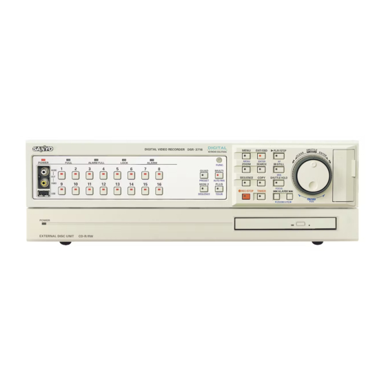
Page 9: Names And Functions Of Parts (Front Panel)
Names and functions of parts (front panel) DSR-3716 G H I J Power indicator (POWER) Audio output terminal (AUDIO OUT) On: The power cord at the rear panel of the DVR is inserted in The audio output is the same as that of the rear panel AUDIO the outlet. - Page 10 Names and functions of parts (front panel) L M N Open Pull out Front Insert Fold down Lift and (lock) push Menu button and indicator (MENU) Timer-controlled recording button and indicator (TIMER) On: The menu is displayed. On: Timer-controlled recording or standby. Off: The EXIT/OSD button is pressed.
-
Page 11: Names And Functions Of Parts (Rear Panel)
Basic connections 3 Video input terminal (VIDEO IN) 1 Clear button (ALL RESET) Connect SANYO protocol cameras (dome or zoom) or generic Press to reset the clocks connected to the digital video cameras to these terminals. recorder to their initial values. -
Page 12: Alarm And Rs-485 Connections
Names and functions of parts (rear panel) Alarm and RS-485 connections 1 Alarm input terminals (ALARM IN) 2 Sensor alarm output terminals Connecting a switch or security sensor etc. to the terminal of the (SENSOR ALARM OUT) DVR allows the detection of the intrusion of outsiders when doors This terminal is used to output the signals listed below etc. -
Page 13: Control Terminals (Control)
Names and functions of parts (rear panel) Control terminals (CONTROL) This DVR can be remotely controlled when a remote-control circuit (R1, R2, C) similar to that shown below is connected to the remote-control terminals. • Use a resistance of 1/10 ohms or more and with a D ranking (Precision within ±0.5%). •... -
Page 14: How To Use
Preparing for use Turn on the power of the DVR Language, clock settings Connect the supplied power cable. Press the MENU button and turn the S-dial clockwise 3 times. The power indicator turns on, and the monitor displays the "PLEASE SET THE CLOCK !" message. "ENGLISH"... -
Page 15: Operation Display
Preparing for use Operation display The operation display shows information necessary for operation, Changing the position of the operation display such as the date, time and video quality. The operation display can Whenever the EXIT/OSD button is pressed, the position of be hidden. -
Page 16: Viewing Live Video Using Various Multi Screens
Viewing live video using various multi screens Switching to another full-screen video Enlarging an image in multi-screen mode Press the camera selection button (example 2, 9) of the Press the PLUS button. desired camera. One camera image is displayed enlarged. The video from Camera 2, then the video from Camera 9 are PLUS (Multi-16 mode) -
Page 17: Automatic Screen Scrolling
Viewing live video using various multi screens Automatic screen scrolling Viewing on the monitor connected to the MON2 terminal A Automatic full-screen scrolling Connect a monitor to the MON2 terminal on the rear panel. The Press the SEQUENCE button. display is full-screen only. (P10) The live surveillance video scrolls through the cameras in the While the main monitor is used in split-screen mode, the monitor 2 order of the camera numbers. -
Page 18: Recording Video To The Hard Disk
Recording video to the hard disk The internal hard disk is automatically formatted with Normal recording recording area, normal recording, recording conditions, etc. (normal recording area) Before starting recording, verify the recordable duration for normal recording. The formatting can be modified using Video from all cameras connected to the video input terminals of "Recording settings". -
Page 19: Viewing Recorded Video
Viewing recorded video (Normal recording area) This DVR can play video that has already been recorded or Full-screen viewing currently being recorded in the normal recording area (by normal or timer-controlled recording). Press the PLAY/STOP button. Normal recording area Video stored in the normal recording area is played back from the starting point of recording. -
Page 20: Changing The Playback Speed
Viewing recorded video Changing the playback speed Viewing still images The corresponding symbol ( ...) appears in the operation Press the STILL button during playback. display area for each of these operations. The image is paused. The " " symbol appears in the operation Audio will not be played when changing the playback speed. -
Page 21: Enlarged Viewing
Viewing recorded video Enlarged viewing Quad-screen viewing The zoom function is not available in multi-screen (4/9/16), plus If video is recorded from a number of cameras, the recorded screen mode or on the monitor connected to MON2. videos can be played back in a quad-screen format. Images become coarser during zooming. -
Page 22: Searching For Recorded Video
Searching for recorded video Video stored in the normal recording area, alarm recording area or archive recording area can be located by searching and then played back. Use one of the five search methods to locate the required video. Alarm search (P22) Press the SEARCH button: Searches and plays alarm video from the SEARCH... -
Page 23: A Alarm Search
Searching for recorded video Alarm search Alarm thumbnail search Press the SEARCH button during recording or live Press the SEARCH button during recording or live video. video. Turn the J-dial, select "ALARM SEARCH", and turn the Turn the J-dial, select "ALARM THUMBNAIL SEARCH", S-dial clockwise. -
Page 24: C Date/Time Search
Searching for recorded video Date/time search Press the SEARCH button during recording or live Select the number using the J-dial, and then turn the video. S-dial clockwise to set it. Repeat the procedure until the entire date/time setting is complete. The cursor moves to "PREVIEW". -
Page 25: D Archive Area Search
Searching for recorded video Archive area search Motion detection search Plays back video stored in the archive area. • Select the search area and the channel number on the <MOTION DETECTION SEARCH 1> screen. Selecting the Press the SEARCH button during recording or live <START PREVIEW>... - Page 26 Searching for recorded video Motion detection search (continued) Repeat the same steps as shown at 8 to set the end Press the SEARCH button during recording or live video. date and time for the search. Example: November 29, 2006 8:30pm Turn the J-dial, select "MOTION DETECTION SEARCH", and turn the S-dial clockwise.
-
Page 27: Motion Sensor Settings Verification Using The Preview Screen
Searching for recorded video Motion detection search (continued) b Motion sensor settings verification using the b Full-screen viewing of video detected by the motion preview screen sensor <MOTION DETECTION SEARCH 2> <MOTION DETECTION SEARCH 2> SEARCH FROM : ALARM / CHANNEL : 4 SEARCH FROM : ALARM / CHANNEL : 4 START :... -
Page 28: Copying Recorded Video To Media
Copying recorded video to media Selected video stored in the normal recording area and the alarm recording area can be copied to various media (full screen). Images copied to a CompactFlash card can be directly printed on a printer. Copying video from the normal or alarm Copying video from the internal hard recording area to the archive area (P28) disk to media such as a CompactFlash... -
Page 29: A Copying Video (Example: 10 Seconds) From The Normal Or Alarm Recording Area To The Archive Area
Copying recorded video to media Copying video (example: 10 seconds) from the normal or alarm recording area to the archive area Start playback from the normal or alarm recording area. Turn the J-dial to select "SECONDS", and then turn the S-dial clockwise. -
Page 30: B Copying Video (Example: 10 Pictures) From The Internal Hard Disk To The Cd-R/Rw Drive
Copying recorded video to media Copying video (example: 10 pictures) from the internal hard disk to the CD-R/RW drive Connect the optional CD-R/RW drive to the USB • EVENTS allows you to copy the data of the archive area per event. -
Page 31: C Copying Video (Example: 10 Pictures) From The Internal Hard Disk To Media Such As A Compactflash Card
Copying recorded video to media Copying video (example: 10 pictures) from the internal hard disk to media such as a CompactFlash card Copy to a MicroDrive is also possible, up to 2GB. Turn the J-dial to select HOW MANY "10", and then turn the S-dial clockwise. -
Page 32: D Printing Images Directly From The Compactflash Card Or The Microdrive
• If "CF→PRINT" is selected, the time necessary to copy is about twice as long as (1MB per 30 seconds) when "COMPACT FLASH" is selected. • Use the SANYO DVP-P1 Digital Photo Printer. Operation is not guaranteed if using another printer. How to use... -
Page 33: Compactflash Cards Or Cd-Rw Formats
• The microdrive can be formatted in the same way. With a CompactFlash Insert the CompactFlash in the CompactFlash card slot. 1st layer 2nd layer 3rd layer 4th layer SANYO _VIEWER IJL15.DLL Press the PLAY/STOP button, the STILL button, and the J2KCOREX.DLL VIEWER2.EXE COPY button. -
Page 34: How To Set
Main menu configuration The main menu consists of seven items, and can be displayed by pressing the MENU button. b Default value settings (P34) <INITIAL SET> 1.LANGUAGE/CLOCK SET -> 2.CAMERA DETECT -> 3.TITLE SET -> 4.HOLIDAY SET -> 5.TIME PERIOD SET ->... -
Page 35: Basic Settings
Basic settings Menu configuration b Displaying the basic settings screen A Language setting Press the MENU button. ☞ Language, Clock setting (P13) The <MAIN MENU> screen is displayed. <LANGUAGE/LANGUE/IDIOMA> Sets the date and time for displaying on the ENGLISH <CLOCK SET> MENU normal screen. -
Page 36: A Daylight Saving Setting
Basic settings Daylight saving setting External clock setting (EXT. CLOCK SET) Automatic switching from standard time to daylight saving can be set. Connect the CLOCK OUT terminal of the CONTROL terminal block on the rear panel of the DVR to the CLOCK IN terminal Display the <LANGUAGE/LANGUE/IDIOMA>... -
Page 37: C Title Setting
Basic settings Title setting Holiday setting ☞ Titles for each camera can be up to 10 characters. Setting conditions Set the start and end time for Sunday (SUN) using the <TIMER Display the <TITLE SET> screen as explained in SET>, and then switch the "SET" to "ON". (P51) "Displaying the basic settings screen"... -
Page 38: E Time Period Setting
Basic settings Time period setting The time period setting allows for using different settings, Display the <TIME PERIOD SET> screen as explained in such as automatic scrolling, masking, motion sensor "Displaying the basic settings screen" (P34). detection settings for four periods of the day (for example: The <TIME PERIOD SET>... -
Page 39: Changing The Time Period Of Operations
Basic settings Time period setting (continued) b Changing the time period of operations Set automatic scrolling, masking or motion sensor for the time periods (A/B). Turn the S-dial clockwise. The default setting for "SELECT TIME PERIOD" is A for all The cursor moves "TIME PERIOD A". -
Page 40: Recording Settings
Recording settings Menu configuration b Displaying the recording settings screen Easy recording settings <NORMAL REC EASY SET> (P40) RECORDING DURATION BASE -> Press the MENU button and use the The recording duration or rate can be selected. J-dial to select "2. RECORD SET", REC RATE BASE ->... -
Page 41: A Easy Recording Menu Description
Recording settings Easy recording menu description The following two easy settings are available. ☞ ☞ Easy recording settings 1 (P41) Easy recording settings 2 (P42) <RECORDING DURATION BASE> <REC RATE BASE> RECORDING DURATION : -- DAYS REC RATE : ----- FPS/CAM TIMER RECORDING(DLY) : OFF TIMER RECORDING(DLY) : OFF START --:--... -
Page 42: Easy Recording Settings 1
Recording settings Easy recording settings 1 Setting the recording based on duration Set the timer. Proceed to 5 if timer setting is not necessary. Display the <NORMAL REC EASY SET> screen as Turn the S-dial clockwise. explained in "Displaying the recording settings screen" The "OFF"... -
Page 43: Easy Recording Settings 2
Recording settings Easy recording settings 2 Set the recording based on recording rate Set the timer. Proceed to 5 if timer setting is not necessary. Display the <NORMAL REC EASY SET> screen as Turn the S-dial clockwise. explained in "Displaying the recording settings screen" The "OFF"... -
Page 44: B Recording Area Menu Description
Recording settings Recording area menu description This screen is used to verify the total capacity of the hard disk, and the recording capacity of the individual recording areas. The recording areas can be modified as needed. Modifying the recording areas will result in initializing the hard disk, and all recordings to be erased. -
Page 45: Changing The Normal Recording Area And The Alarm Recording Area
Recording settings Changing the normal recording area and the alarm recording area This operation will initialize the hard disk. Turn the J-dial to set the "ALARM RECORDING AREA" (49% in the example), and turn the S-dial clockwise. Display the <RECORDING AREA SET> screen as The cursor moves to "AREA FULL RESET"... -
Page 46: Archive Area Full Reset
Recording settings Archive area full reset The archive area cannot be automatically overwritten. Performing "AREA FULL RESET" will erase all images from the archive area. Display the <RECORDING AREA SET> screen as explained in "Displaying the recording settings screen" (P39). <MAIN MENU>... -
Page 47: C Recording Conditions Menu Description
Recording settings Recording conditions menu description This menu is used to set whether to continue recording and automatically overwrite data, or stop recording without overwriting the data when the normal recording area and the alarm recording area of the hard disk become full. <RECORDING CONDITIONS SET>... -
Page 48: Overwrite Setting For The Recording Areas
Recording settings Overwrite setting for the recording Setting series recording areas If multiple DVR units are connected, recording can be automatically continued on the next DVR when the recording Display the <RECORDING CONDITIONS SET> screen as area of the first one becomes full. explained in "Displaying the recording settings screen"... -
Page 49: Series Recording
Recording settings Setting series recording (continued) Series recording Display the <RECORDING CONDITIONS SET> screen as Start recording on the first DVR. explained in "Displaying the recording settings screen" • Press the REC/STOP button if using normal recording or (P39). normal recording combined with alarm recording. •... -
Page 50: D Normal Recording Area Menu Description
Recording settings Normal recording area menu description Normal recording area settings This menu is used to set the picture quality, audio recording Display the <NORMAL REC MODE SET> screen as and recording rate for the normal recording area. A program explained in "Displaying the recording settings screen", number can be selected at the programmed recording and then turn the S-dial clockwise. -
Page 51: E Programmed Recording Menu Description
Recording settings Programmed recording menu Programmed recording settings description Display the <PROGRAM REC SET> screen as explained in "Displaying the recording settings screen", and then This menu is used to set the desired cameras for each group turn the S-dial clockwise. (P39) (P-1, P-2, P-3 and P-4) for programmed recording. -
Page 52: F Timer Setting Menu Description
Recording settings Timer setting menu description This menu is used to set the start and end times for timer-controlled recording. The following timer functions are available: Day of the week timer-controlled recording (same time and same recording rate every week for the specified day) (P52) <TIMER SET>... -
Page 53: Day Of The Week Timer-Controlled Recording (Same Time, Same Recording Rate Every Week For The Specified Day)
Recording settings Day of the week timer-controlled recording (same time, same recording rate every week for the specified day) Display the <TIMER SET> screen as explained in Press the TIMER button. "Displaying the recording settings screen", and then The TIMER indicator turns on, and the timer-controlled turn the S-dial clockwise. -
Page 54: Overlapping Timer-Controlled Recording
Recording settings Overlapping timer-controlled recording Display the <TIMER SET> screen as explained in Press the EXIT/OSD button. "Displaying the recording settings screen". (P39) EXIT/OSD <MAIN MENU> MENU 2.RECORD SET Press the TIMER button. <RECORD SET> The TIMER indicator turns on, and the timer-controlled 6.TIMER SET recording goes into standby mode. -
Page 55: External Timer-Controlled Recording
Recording settings External timer-controlled recording b Setting a program for timer-controlled recording Connect an external timer device to the EXT TIMER IN terminal on the rear panel (Figure 1). Perform the following settings to set a program after setting the timer-controlled recording. -
Page 56: G Alarm Recording Settings Menu Description
Recording settings Alarm recording settings menu description The following settings can be performed under the alarm recording settings. Alarm recording (P56) These settings control the picture quality, audio recording and <ALARM REC MODE SET> recording rate for the alarm recording area, when an alarm is ALARM RECORDING : OFF PICTURE QUALITY... -
Page 57: Alarm Recording Settings
Recording settings Alarm recording settings Display the <ALARM REC MODE SET> screen as Turn the J-dial to select the recording pattern explained in "Displaying the recording settings screen", (ALARM INTERLEAVE), and then turn the S-dial twice and then turn the S-dial clockwise. (P39) clockwise. -
Page 58: Pre-Alarm Recording Settings
Recording settings Turn the J-dial to select the REC RATE (example: Pre-alarm recording settings 7.5), and then turn the S-dial clockwise. Repeat the same procedure to set the DURATION Display the <ALARM REC MODE SET> screen as (example: 20). explained in "Displaying the recording settings screen", After the arrow symbol (=>) the number of alarms that and then turn the S-dial clockwise. -
Page 59: Motion Sensor Screen Description
Recording settings Motion sensor screen description Use this screen for motion sensor setting on a live video screen to detect moving objects such as intruders, and generate alarms. The motion sensor detects movement based on intensity-changes on the screen. It is necessary to use sensor settings that are appropriate for both the location of the sensor and for the observed objects. -
Page 60: Motion Sensor Setting
Recording settings Motion sensor setting Set "TIME PERIOD A" and "TIME PERIOD B" using Turn the J-dial, set the sensor to "A", and turn the <TIME PERIOD SET> (P37). S-dial clockwise. When "A" is accepted, the cursor moves to the right, to Display the <ALARM REC MODE SET>... -
Page 61: H Alarm Operation Settings Menu Description
Recording settings Alarm operation settings menu description This menu is used to extend the duration of the alarm (2) If another channel detects a second alarm during recording and to set the display method when an alarm DURATION operation and the same channel detects a occurs. -
Page 62: Alarm Operation Settings
Recording settings Alarm operation settings Alarm display settings Display the <ALARM OPERATION SET> screen as Turn the J-dial, select "MAIN MON. DISPLAY", and turn explained in "Displaying the recording settings screen", the S-dial clockwise. and then turn the S-dial clockwise. (P39) Selections: FULL/9/16/NC The "OFF"... -
Page 63: General Settings
General settings Menu configuration b Displaying the general settings screen A Data display settings/ <DISPLAY SET> DATE : ON VIDEO LOSS settings (P63) TIME : ON Press the MENU button and use the QUALITY : ON AUDIO : ON J-dial to select "3. GENERAL SET", ALARM COUNT : ON and then turn the S-dial clockwise. -
Page 64: A Data Display Settings/Video Loss Settings
General settings Data display settings/VIDEO LOSS settings These settings are used to control the operating display area Turn the J-dial, select "VIDEO LOSS", and turn the of the monitor, to display the date, time and other S-dial clockwise. information. Normally all indicators are displayed, but they The "ON"... -
Page 65: B Buzzer Settings
General settings Buzzer settings These settings are used to generate a warning buzzer when Press the EXIT/OSD button. the hard disk is full and at alarm events. EXIT/OSD Display the <BUZZER SET> screen as explained in "Displaying the general settings screen", and then turn the S-dial clockwise. -
Page 66: C Security Lock Menu Description
General settings Security lock menu description Turn ON the ADMIN and USER security locks and set passwords for the DVR This menu is used to set passwords and to limit access to the DVR. There are two passwords, one for the administrator, and Refer to P67 for information on the control rights after setting one for the user. -
Page 67: Activating The Security Lock
General settings Activating the security lock Cancelling the security lock When the administrator and user level settings are complete, Press one of the operation buttons on the front panel. activate the security lock. The "SECURITY LOCKED!" screen appears for about 5 seconds. -
Page 68: List Of Permitted Operations After Setting The Passwords
General settings b List of permitted operations after setting the passwords <SECURITY LOCK SET> LEVEL PASSWORD(4-8) USE ADMIN -------- USER -------- REC CONTROL : ADMIN If both the ADMIN and USER are "ON": CAMERA CONTROL : ADMIN • If the ADMIN password is entered, all operations will be permitted. -
Page 69: D Hard Disk Settings Menu Description
We recommend using the expansion hard disk provided by SANYO. Operation is not guaranteed if a hard disk other than SANYO's recommended type is used for capacity expansion. • The hard disks must be initialized, upon installing an expansion disk. -
Page 70: E Network Settings
General settings Network settings Network password modification Connecting the DVR to the network There are three access levels (ID1, ID2, ID3) to connect to the network. Refer to the Network connection terminals (LAN). (P11) The default settings for the IDs are shown below: Display the <NETWORK SET>... -
Page 71: F Rs-485 Settings
General settings RS-485 settings Connect the RS-485 terminal on the rear panel of the Figure 1 (Do not use telephone wires.) DVR with the system controller (Figure 1). System controller Display the <RS-485 SET> screen as explained in (sold separately) "Displaying the general settings screen", and then turn RS485 B the S-dial clockwise. -
Page 72: G Camera Control Settings
OFF: No camera control superimposed dome camera. SANYO COAX1: If the protocol settings are set to "OFF" the "ALARM REC Camera control by coaxial superimposition of the SANYO TRIGGER SET" cannot be set. (SSP) protocol. The address is automatically displayed. -
Page 73: Alarm Recording Trigger Settings
General settings Alarm recording trigger settings Depending on the settings of the selections under "ALARM Turn the J-dial to select the motion operation (example: RECORDING", the camera lens can be set to move to a preset 05 SEQUENCE) and then turn the S-dial clockwise. position or automatic panning when an alarm is detected. -
Page 74: Camera Control From The Dvr
General settings Camera control from the DVR b Camera control is not possible in the following cases, even if the function indicator (FUNC.) is ON. • While displaying menus, or the search menu • During playback (during pause, or copy menu is display) •... -
Page 75: Screen Setting
-> MAIN MON. OFF OFF OFF OFF OFF OFF OFF OFF MON.2 OFF OFF OFF OFF OFF OFF OFF OFF (DSR-3716) NETWORK OFF OFF OFF OFF OFF OFF OFF OFF 09 10 11 12 13 14 15 16 MAIN MON. OFF OFF OFF OFF OFF OFF OFF OFF MON.2... -
Page 76: A Changing The Multi-Screen Sequence
Screen setting Changing the multi-screen sequence Display the <SCREEN SET> screen as explained in Example: Switching the live video of the camera 5 and "Displaying the screen settings", and then turn the camera 1 on the quad screen. S-dial clockwise. (P74) Turn the J-dial, select "QUAD POSITION SET", and The "NORMAL"... -
Page 77: Automatic Scrolling Of Live Video Of The Main Monitor And The Monitor 2 At Identical Intervals (Example: 5 Seconds)
Screen setting Automatic scrolling of live video of the main Automatic scrolling of live video of the main monitor and the monitor 2 at identical monitor and the monitor 2 at individual intervals (example: 5 seconds) intervals (example: 5 seconds) Display the <SCREEN SET>... -
Page 78: Automatic Sequence Of Live Video Of The Main Monitor (Full-Screen) At Individual Intervals, And Of The Monitor 2 At Identical Intervals (Example: 3 Seconds)
Screen setting Automatic sequence of live video of the main Turning off display of specified monitor (full-screen) at individual intervals, cameras during timer-controlled and of the monitor 2 at identical intervals periods (example: 3 seconds) Set TIME PERIOD A and TIME PERIOD B using <TIME PERIOD SET>... -
Page 79: C Masking Specific Camera Images
Screen setting Masking specific camera images Set TIME PERIOD A and TIME PERIOD B using <TIME Turn the S-dial, and use the J-dial to select the desired PERIOD SET> (P37). TIME PERIOD (example: T-2), and then turn the S-dial clockwise. Select "TIME PERIOD A"... -
Page 80: D Adjusting Color Tones Of The Live Video
Screen setting Adjusting color tones of the live video Display the <SCREEN SET> screen as explained in "Displaying the screen settings" (P74). The cursor moves to the 1. MULTI SCREEN position. <MAIN MENU> MENU 4.SCREEN SET <SCREEN SET> 1.MULTI SCREEN : NORMAL QUAD POSITION SET ->... -
Page 81: Power Loss Information/Used Time
Power loss information/Used time Power loss/Used time menu description Viewing the information Use this procedure to view the power loss dates and times, hard disk running times, and the power-on time of the DVR. <POWER LOSS/USED TIME> Press the MENU button, turn the J-dial, select POWER LOSS RECOVER... -
Page 82: Initialization Log
Initialization log Initialization log menu description Viewing the log Use this procedure to view the hard disk initialization and area reset log. The log displays the eight most recently performed operations. Press the MENU button, turn the J-dial, select <INITIALIZATION LOG> "6.INITIALIZATION LOG", and then turn the S-dial DATE TIME... -
Page 83: Menu Copy
Menu copy Menu copy screen description Save the menu content in the CF card. Save the set menu on the CF card and load the same menu Insert the CF card into the CF card slot onto a different DVR of the same model. It is possible to 2 Pull out 1 Open control several units using the same menu. -
Page 84: Load Menu Content Saved To The Cf Card Onto Other Dvrs Of The Same Model
Menu copy Load menu content saved to the CF card onto other DVRs of the same model. Press the MENU button in order to display the <COPY B) When "YES" is selected for COPY RECORDING MENU SETTINGS> screen and load the menu content AREA SETTINGS (Initialized). -
Page 85: Interface (Rs-485) Specifications
Communication protocol It is recommended that the exclusive controller is used for Mode Asynchronous operation as a protocol unique to our company (SANYO protocol) Character length 8 bits is used for this DVR. Consult the service center regarding the... -
Page 86: Specifications
Zero voltage make connection (pulse width Recording area Normal recording area/alarm recording area/ 100m/second and over) archive area (DSR-3716: x16, DSR-3709: x9) Zoom 2x digital zoom is possible using the ZOOM Sensor alarm output Open collector/1kΩ, Low level active button (max. -
Page 87: List Of Recording Rate And Recording Times
List of recording rate and recording times The recording time on this DVR are adjusted automatically when the recording rate and the recording quality have been altered. The list below displays the recording rate and quality when recording images within the hard disk normal recording area of this DVR. •... - Page 88 List of recording rate and recording times b When recording using an 500GB hard disk (when 99% of the area is utilized) Recording time Recording rate BASIC NORMAL ENHANCED FINE SUPER FINE (fields/second) 15kB 22kB 30kB 42kB 50kB 126 (H) 89 (H) 66 (H) 48 (H)
-
Page 89: List Of Record Rate Setting/Pre-Alarm Recording Times
List of record rate setting/pre-alarm recording times b Recording rate setting Normal recording Pre-alarm recording Program recording Recording rate (FPS) Alarm recording (Note 1) (Note 2) (Note 1) (Note 3) 4.286 3.75 3.333 2.727 2.308 1.875 1.667 1.429 1.25 1.111 0.333 0.25 0.05... -
Page 90: Push-Lock Terminal Specifications
Push-lock terminal specifications Input/output terminals Signal level Input/output circuit Open grounded <ALARM IN> input 100kΩ 1kΩ [0 voltage contact] Terminal 74HC597 Over 100 ms 10kΩ Open <SENSOR ALARM OUT> 1kΩ [Open collector/1kΩ, Low Level active Terminal BU209 (max. 25 mA)] Motion sensor detection Alarm recording stop <Control terminals>... -
Page 91: List Of Camera Addresses
• When using the VSP-9000 system controller’s SSP (SANYO’s security serial protocol) to operate a camera that is connected to the DVR, make sure that Address for DVR connected to camera (A), Channel for DVR (B) and SSP ADDRESS for CAMERA (C) have been set correctly. - Page 92 SANYO Electric Co., Ltd. 1AC6P1P2999-- L8HBK/US, L8HBL/US (1205KP-SY)
Need help?
Do you have a question about the DSR-3716 and is the answer not in the manual?
Questions and answers