Table of Contents
Advertisement
Quick Links
Advertisement
Table of Contents

Related Manuals for Sanyo DSR-3506


Summary of Contents for Sanyo DSR-3506
- Page 1 Refer to the included CD-ROM for the French and Spanish “INSTRUCTION MANUAL”. Utilisez le CD-ROM fourni pour consulter le “MANUEL D’INSTRUCTIONS” en français et en espagnol. Consulte en el CD-ROM el “MANUAL DE INSTRUCCIONES” en francés y en español.
-
Page 2: Declaration Of Conformity
Model Number : DSR-3506 RISK OF ELECTRIC SHOCK Trade Name : SANYO DO NOT OPEN Responsible party : SANYO FISHER COMPANY CAUTION: Address : 21605 Plummer Street, TO REDUCE THE RISK OF ELECTRIC SHOCK, DO NOT REMOVE COVER (OR BACK). -
Page 3: Main Features
Searching by date/time Searching within the archive area Copyright Searching for intruder motion using motion detection This manual and software are copyrighted by Sanyo search Electric Co., Ltd. Two-level security lock function - lets you Brand and product names used in this manual are the... -
Page 4: Table Of Contents
CONTENTS INTRODUCTION 1 BEFORE USE..........5 2 NAMES AND FUNCTIONS OF PARTS ..7 Notes on handling the internal HDD ....5 Front panel ............7 Notes on installation locations ......5 Rear panel............9 The hard disk and cooling fan are consumable components.........6 3 INSTALLATION AND CONNECTIONS .. - Page 5 CONTENTS SETTINGS 1 MENU CONFIGURATION AND 4 GENERAL SET..........76 OPERATIONS ..........39 General settings ..........76 Basic menu operations ........39 Setting data display........76 Restoring menu setting items to their Setting display for video loss......77 default values..........40 Setting the buzzer ......... 78 Sub-menu configuration ........41 Setting the security lock ........
-
Page 6: Before Use
BEFORE USE Notes on handling the internal HDD Notes on replacing the HDD Be sure to follow the correct procedure when replacing the This digital video recorder uses an internal hard disk drive HDD. (HDD). HDDs that have been removed from their packing may Be sure to observe the following points carefully when not operate correctly if they are subjected to sudden operating, setting-up, or servicing the digital video... -
Page 7: The Hard Disk And Cooling Fan Are Consumable Components
Always perform test recording in advance to confirm whether the digital video recorder’s playback is normal. Note that Sanyo will accept no responsibility for losses occurring as a result of recording or playback problems caused by malfunction of this digital video recorder or any connected devices. -
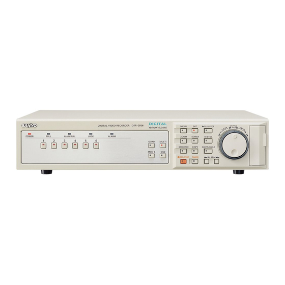
Page 8: Names And Functions Of Parts
NAMES AND FUNCTIONS OF PARTS MENU EXIT PLAY/STOP SHUTTLE POWER FULL ALARM FULL LOCK ALARM ZOOM SEARCH STILL QUAD MULTI SEQUENCE COPY SHUTTLE HOLD MON 2 REC/STOP TIMER ALARM MENU RESET 20 21 Front panel During quad or multi 6 screen display: The indicators corresponding to the cameras being POWER indicator displayed on the monitor are lit up. - Page 9 NAMES AND FUNCTIONS OF PARTS MENU EXIT PLAY/STOP SHUTTLE POWER FULL ALARM FULL LOCK ALARM ZOOM SEARCH STILL QUAD MULTI SEQUENCE COPY SHUTTLE HOLD MON 2 REC/STOP TIMER ALARM MENU RESET 20 21 12. [EXIT] button and indicator When a password has been set, furthermore, this button The [EXIT] button is used to exit the main menu or a sub- can be pressed for at least three seconds to activate the menu.
-
Page 10: Rear Panel
NAMES AND FUNCTIONS OF PARTS ALARM FULL ALARM RISET ALARM IN AC IN VIDEO SENSOR ALARM OUT ALARM OUT MAIN REMOTE MON2 MONITOR C R1 R2 RESET MIC IN AUDIO Rear panel 11. [ALL RESET] button When the [ALL RESET] button is pressed, the digital video VIDEO IN terminals recorder is reset and the time is returned to its default VIDEO OUT terminals... -
Page 11: Installation And Connections
INSTALLATION AND CONNECTIONS This section describes how to connect the digital video recorder to video cameras and other devices. Be sure to read the instruction manuals for each connected device. Improper connections can result in malfunction or the emission of smoke. A separate power supply is required for operation of each camera. -
Page 12: Operation
INSTALLATION AND CONNECTIONS Connecting SENSOR ALARM OUT Connecting the power cord terminals When you have finished making all the other connections, make sure the The sensor alarm output terminals are used to relay alarm voltage is 120V-240V AC and insert the signals whenever one of the digital video recorder’s motion power plug into the wall outlet. -
Page 13: Preparing For Use
PREPARING FOR USE (5) Picture quality display ( P.62,68) Operation display area Displays the quality of the video that can be recorded on the hard disk. Set to “EN” (Enhanced) by default. Whenever the power is turned on, the operation display Basic area will be shown at the top of the monitor screen. -
Page 14: Changing The Position Of The Operation Display Area
PREPARING FOR USE Turn the jog dial to select “1. Changing the position of the LANGUAGE/CLOCK SET”, and then operation display area turn the shuttle dial clockwise. Press the [OSD] button several times. The <LANGUAGE/LANGUE/IDIOMA> screen is displayed with the cursor positioned on “ENGLISH”. As the [OSD] button is pressed, the operation display area moves to a different location or is hidden. -
Page 15: Setting The Time
PREPARING FOR USE Turn the shuttle dial clockwise. Setting the time “01” flashes (indicating the month). (Default: 01-01-2004 THU 00:00:00) Be sure to set the correct date and time as these settings are used during recording and searching. Example: Setting 8:30 on May 22, 2004 Press the [MENU] button. -
Page 16: The Internal Hard Disk
PREPARING FOR USE The internal hard disk If the memory allocations for the various hard disk recording areas are changed during a recording process, all stored recordings will be deleted and the hard disk will be initialized; accordingly, special care should be taken. -
Page 17: Viewing Video From A Camera
VIEWING VIDEO FROM A CAMERA [MULTI] button [SEQUENCE] button [CAMERA SELECT] buttons [MON2] button [QUAD] button Viewing on multiple screens Viewing on a full screen Use the following procedure to display video from the Example: Selecting Camera 2 connected cameras in split-screen format. Press the No. -
Page 18: Viewing With Automatic Screen Selection
VIEWING VIDEO FROM A CAMERA Viewing on multi 6 screens Setting automatic quad-screen selection Press the [MULTI] button. Press the [QUAD] button. The MULTI indicator lights up and the monitor display is The QUAD indicator lights up and the monitor display is divided in six. -
Page 19: Viewing On The Monitor 2
VIEWING VIDEO FROM A CAMERA Viewing on the monitor 2 Setting automatic full screen selection Press the [SEQUENCE] button. When a monitor 2 is connected to the monitor 2 output The video displayed on the monitor 2 changes terminal on the digital video recorder’s rear panel, this automatically based on camera numbers. -
Page 20: Recording
RECORDING POWER indicator FULL indicator [REC/STOP] button [TIMER] button Normal recording Timer recording Use the following procedure to record the monitored video Use the following procedure to record the monitored video in the normal recording area. for a preset length of time in the normal recording area. Recording will not be possible until a time has been set for Recording will not be possible until a time has been set for the digital video recorder. -
Page 21: Alarm Recording
RECORDING POWER indicator [EXIT] button ALARM FULL indicator [REC/STOP] button [TIMER] button Alarm recording When an alarm signal is detected When an alarm signal is detected, “ALARM” flashes in Use the following procedure to automatically record alarm the operation display and the alarm recording starts video to the alarm recording area when an alarm signal is (indicated by “REC”). -
Page 22: Pre-Alarm Recording
RECORDING Pre-alarm recording If an alarm is detected Pre-alarm recording is automatically ended and alarm Use the following procedure to record video from recording starts. immediately before occurrence of an alarm. “PRE” from the operation display area is replaced by “ALARM”, and “ALARM”... -
Page 23: Playback
PLAYBACK Use the procedures following procedure to play video stored in the normal recording area (during normal or timer recording). [PLAY/STOP] button POWER indicator Normal Shuttle dial recording area [SHUTTLE HOLD] button Jog dial Playing video on a full screen Fast-forward and fast-rewind playback Press the [PLAY/STOP] button. -
Page 24: Enlarging The Playback Video
PLAYBACK (3) Returning to normal playback. Enlarging the playback video Turn the jog dial slightly clockwise to display “ ”. Press the [ZOOM] button during playback. Zoom indicator lights and a blue zoom frame appears in the center of the screen. Audio will not be played during fast-forward, fast- ZOOM rewind, slow, reverse-slow, and reverse playback. -
Page 25: Viewing Still Images
PLAYBACK Turn the shuttle dial clockwise. Viewing still images The area enclosed by the zoom frame is magnified (by a Press the [STILL] button during playback. factor of 2). The STILL indicator lights up and playback video is paused. 01-01-04 00:00:00 EN A ALARM 0000 The symbol “... -
Page 26: Playing Video On Multiple Screens
PLAYBACK Playing video on multiple screens Playing video on six screens If you are recording video from a number of different Press the [MULTI] button during cameras, the following procedures can be used to play the playback. recorded video in multi-screen format. The MULTI indicator lights up and the monitor display is divided in six. -
Page 27: Searching For Recorded Video
SEARCHING FOR RECORDED VIDEO Images stored in the normal recording area, alarm (1) ALARM SEARCH ( P.27) Lets you search and playback alarm video from the recording area or archive area can be located by recording list. searching and can then be played back.Use one of the following five search methods locate the required video. -
Page 28: Alarm Search
SEARCHING FOR RECORDED VIDEO Turn the jog dial to move the cursor and Alarm search select the video for playback. Use the following procedure to search and playback all A preview of the selected alarm video is displayed in the video stored in the alarm recording area. -
Page 29: Alarm Thumbnail Search
SEARCHING FOR RECORDED VIDEO When playback is performed after an alarm search, the To leave search mode frame at the start and end of each alarm recording will Press the [SEARCH] button. SEARCH indicator turns off. be paused. Press the appropriate [ALARM] button to play the Turn the shuttle dial clockwise. - Page 30 SEARCHING FOR RECORDED VIDEO Turn the shuttle dial clockwise. Turn the shuttle dial clockwise. After searching, the recording for the date and time The <TIME/DATE SEARCH> screen is displayed. settings is displayed in the preview screen. (1) RECORDING TOP: If no recording exists for the specified time Indicates the date/time of the earliest video recording.
-
Page 31: Archive Area Search
SEARCHING FOR RECORDED VIDEO Turn the jog dial to select the video for Archive area search playback. The selected image is displayed on the preview screen. Use the following procedure to playback video that has been stored in the archive area. Press the [SEARCH] button while the digital video recorder is recording or stopped. - Page 32 SEARCHING FOR RECORDED VIDEO Turn the jog dial to select “MOTION Turn the shuttle dial clockwise, and DETECTION SEARCH”, and then turn then turn the jog dial to select a camera the shuttle dial clockwise. number. The <MOTION DETECTION SEARCH> screen is (Selection example: 4) displayed.
- Page 33 SEARCHING FOR RECORDED VIDEO (2) Turn the shuttle dial clockwise to set a motion sensor. Set the motion sensor to use for : ON, : OFF searching. Turn the shuttle dial clockwise while video is being displayed on the preview screen.
- Page 34 SEARCHING FOR RECORDED VIDEO Turn the shuttle dial clockwise. The display returns to the <MOTION DETECTION By specifying a camera number (or channel) and SEARCH> screen. performing “MOTION DETECTION SEARCH”, playback can be carried out for only the specified camera number. In such a case, the title information, date information, and/or time information may partially disappear.
-
Page 35: Saving (Copying) Recorded Video
SAVING (COPYING) RECORDED VIDEO Use the procedures described below to copy important video stored in the normal recording area or the alarm recording area to the digital video recorder’s archive area, a CompactFlash card, or a Microdrive. Copying video to the hard disk’s archive area ( P.35) Copy Copy Alarm recording... -
Page 36: Copying Video To The Hard Disk's Archive Area
SAVING (COPYING) RECORDED VIDEO Turn the jog dial to select “COPY TO”, Copying video to the hard disk’s and then turn the shuttle dial clockwise. archive area “ARCHIVE AREA” starts to flash. [Settings] ( indicates the default setting) [PLAY/STOP] button Setting Description [STILL] button... -
Page 37: Copying Normal Recording Area, Alarm Recording Area, Or Archive Area Video To A Compactflash Card Or Microdrive
SAVING (COPYING) RECORDED VIDEO Turn the jog dial to select “SECONDS”. (2) When this procedure has been completed, “COPY FINISHED!” is displayed. [Settings] ( indicates the default setting) Setting Description To cancel a copy operation The specified number of images after the Press the [COPY] button to cancel the current copy. - Page 38 SAVING (COPYING) RECORDED VIDEO Pause playback on the image to be Turn the shuttle dial clockwise. copied, and then press the [COPY] “PICTURES” flashers. button. The <COPY> screen is displayed. COPY Turn the jog dial to select “SECONDS”. [Settings] ( indicates the default setting) Turn the jog dial to select “COPY TO”, Setting...
-
Page 39: Viewing Images Copied To A Compactflash Card On A Pc
00000003.JPG not recognize FAT32 CompactFlash cards. IMG00003 INDEX.HTM (1) A folder with the name “SANYO” is created inside the root directory. (2) Within this, folders are created based on the date of copied images or video. (3) Within each date folder, sub-directories are created in sequence starting with “IMG00001”. -
Page 40: Menu Configuration And Operations
MENU CONFIGURATION AND OPERATIONS Turn the shuttle dial clockwise. [EXIT] button [MENU] button The sub-menus appear. Shuttle dial The cursor is positioned on the first setting item. Turn the jog dial to select a sub-menu, and then turn the shuttle dial clockwise. Jog dial The corresponding setting screen is displayed, and the This section describes the menu configuration and the... -
Page 41: Restoring Menu Setting Items To Their Default Values
MENU CONFIGURATION AND OPERATIONS Movement and confirmation in sub-menus and setting screens The jog dial and shuttle dial are used for movement and confirmation in sub-menus and setting screens. To move the cursor Turn the jog dial. up or down To move the cursor Turn the shuttle dial right or to confirm... -
Page 42: Sub-Menu Configuration
MENU CONFIGURATION AND OPERATIONS Main menu Sub menu Turn the jog dial to select the item to be set, and then turn the shuttle dial clockwise. Sub-menu configuration The following table indicates the sub-menus or setting screens displayed by selecting items from the <MAIN MENU>. The [MENU] button can be used in any sub-menu to scroll through each of the sub-menus in sequence. - Page 43 MENU CONFIGURATION AND OPERATIONS Sub menu Setting item Settings or display content <SCREEN SET> Specifies the positions of video from different cameras on the quad (1) MULTI SCREEN ( P.86) This sub-menu is used to make and multi 6 screens. screen settings for monitoring.
-
Page 44: Initial Set
INITIAL SET [EXIT] button [MENU] button Main Menu Shuttle dial Jog dial Initial settings Setting Description Ref. The <INITIAL SET> is used to make the following setting. <TIME PERIOD SET> Uses a pair of time periods to P.50 set a time band for operation switching and other functions. - Page 45 INITIAL SET Turn the jog dial to select “1. Turn the shuttle dial clockwise. LANGUAGE/CLOCK SET”, and then The cursor moves to the date/time at which to switch from turn the shuttle dial clockwise. standard time to summer time. The <LANGUAGE/LANGUE/IDIOMA> screen is displayed with the cursor positioned on “ENGLISH”.
-
Page 46: External Clock Setting
INITIAL SET Turn the jog dial to select the desired Turn the jog dial to select “1. INITIAL day of the week, and then turn the SET”, and then turn the shuttle dial shuttle dial clockwise. clockwise. The <INITIAL SET> screen is displayed. The cursor moves to the month. -
Page 47: Detecting Connected Cameras
INITIAL SET Turn the jog dial to set a time, and then Detecting connected cameras turn the shuttle dial clockwise. Use the following procedure to automatically detect (Example: 05:00) cameras that have been connected. An “OFF” setting should be made for cameras that have not been connected. -
Page 48: Setting Camera Titles
INITIAL SET Turn the jog dial to select “YES”, and Turn the jog dial to select “3. TITLE then turn the shuttle dial clockwise. SET”, and then turn the shuttle dial clockwise. Connected cameras are automatically detected. When detection has been completed, the display returns to The normal monitoring screen is displayed with a title the <INITIAL SET>... -
Page 49: Setting Holidays
INITIAL SET Turn the shuttle dial clockwise. Setting holidays The character selection is confirmed and the cursor moves Use the following procedure to set specific dates as one position to the right. holidays to have the operation for Sunday used on those days also. - Page 50 INITIAL SET Turn the jog dial to select “4. HOLIDAY Press the [EXIT] button. SET”, and then turn the shuttle dial The setting procedure is ended and the display returns to clockwise. the normal screen. The <HOLIDAY SET> screen is displayed with the cursor The default setting is all “-----”.
-
Page 51: Setting Time Periods
INITIAL SET Setting time periods Operations during the specified time periods The following menu settings must be made to enable A time period is setup by the two timers TIME PERIOD A operation of the time periods. After completing these and TIME PERIOD B, and the following procedure can be settings, be sure to then carry out timer setting. - Page 52 INITIAL SET Turn the jog dial to select “5. TIME Timer period settings PERIOD SET”, and then turn the shuttle Example 1: Setting periods using TIME PERIOD A and dial clockwise. TIME PERIOD B The <TIME PERIOD SET> screen is displayed. TIME PERIOD A settings Set T1 to 6 AM (6:00) Set T2 to 11:30 AM (11:30)
- Page 53 INITIAL SET Turn the jog dial to set T2 (minutes) to Turn the jog dial to move the cursor to “30” (minutes), and then turn the shuttle “SEQUENCE” within “SELECT TIME dial clockwise. PERIOD”, and then turn the shuttle dial clockwise.
-
Page 54: Record Set
RECORD SET FULL indicator ALARM FULL indicator [EXIT] button Main Menu Shuttle dial [MENU] button Jog dial Settings for recording <PROGRAM REC SET> The <RECORD SET> is used to make the following Sets program recording for P.63 cameras settings. <TIMER SET> Makes timer settings so that operations can be started at a P.65... - Page 55 RECORD SET (1) When the number of cameras detected using Setting based on recording days “CAMERA DETECT” is greater or less than the number of cameras previously stored in the digital video Turn the jog dial to select “RECORDING recorder. DURATION BASE”, and then turn the (2) When the setting for “PRE-ALARM RECORDING”...
- Page 56 RECORD SET Turn the shuttle dial clockwise. [Settings] ( indicates the default setting) Setting Description “OFF” flashes. BASIC (BA) 15 kB NORMAL (NO) 22 kB ENHANCED(EN) 30 kB FINE (FI) 42 kB SUPER FINE (SF) 50 kB Set “AUDIO RECORDING”. (Example: ON) To activate timer operation, turn the jog dial to select “ON”, and then turn the...
- Page 57 RECORD SET Press the [EXIT] button. Turn the shuttle dial clockwise. The setting procedure is ended and the display returns to “60.00” flashes. the normal screen. EXIT The recording rate is automatically calculated based on recording settings and the number of connected cameras, and this is indicated by “REC RATE”.
-
Page 58: Displaying The Recording Areas
RECORD SET The following settings are carried out using the shuttle Displaying the recording areas dial and jog dial. Vertical cursor movement: Turn the jog dial. Use the following procedures to confirm the hard disk’s Cursor movement to the right: Turn the shuttle dial total recording capacity and also the allocation for each clockwise. -
Page 59: Changing Recording Areas
RECORD SET Total capacity following hard disk expansion. If the normal recording area is set to “0%”, the [PLAY/ When “MIRRORING” P.82) is set using “4. HDD SET”, STOP] button will be deactivated. In such a case, the total capacity display will change as follows. search playback should be carried out. -
Page 60: Setting Overwrite Permission
RECORD SET The following settings are carried out using the shuttle dial and jog dial. If the shuttle dial is turned clockwise while “NO” is Vertical cursor movement: Turn the jog dial. selected, the <RECORDING AREA SET> screen will Cursor movement to the right: Turn the shuttle dial be displayed and the recording capacities will revert to clockwise. -
Page 61: Setting Recording Conditions
RECORD SET Turn the jog dial to select “2. Press the [EXIT] button. RECORDING AREA SET” from the The setting procedure is ended and the display returns to <RECORD SET> screen, and then turn the normal screen. the shuttle dial clockwise. EXIT The <RECORDING AREA SET>... -
Page 62: Setting Auto Deleting
RECORD SET Turn the jog dial to select setting (OFF, Press the [EXIT] button. for example), and then turn the shuttle The setting procedure is ended and the display returns to dial clockwise. the normal screen. EXIT “REMAINING DISK WARNING” changes to “1%” from “**”. [Settings] ( indicates the default setting) A warning will be displayed in the operation display area... -
Page 63: Setting Normal Recording
RECORD SET Turn the shuttle dial clockwise. Turn the jog dial to select “4. NORMAL REC MODE SET”, and then turn the Press the [EXIT] button. shuttle dial clockwise. The <NORMAL REC MODE SET> screen is displayed. The setting procedure is ended and the display returns to the normal screen. -
Page 64: Setting Program Recording
RECORD SET Setting program recording Audio recording can only be specified when “REC RATE” is between A 60.00 and A 1.00 FPS. Use the following procedure to record from specified When set to “ON”, the letter “A (indicating that audio will cameras. - Page 65 RECORD SET Turn the jog dial to select “5. PROGRAM Turn the jog dial to select a recording REC SET”, and then turn the shuttle dial rate (3.75, for example), and then turn clockwise. the shuttle dial clockwise. The <PROGRAM REC SET> screen is displayed with the Camera No.
-
Page 66: Timer Settings
RECORD SET Timer settings The settings made using <NORMAL REC MODE SET> are used to set quality and audio recording for timer Use the following procedures to set recording start and recording. ( P.62) stop times using the timer function. Ensure that start and end times are input using 24-hour notation. - Page 67 RECORD SET Turn the jog dial to set “SUN” to “DLY”, and then turn the shuttle dial clockwise. If timer settings overlap, recording is performed in the following sequence. The start time flashes as “--:--”. Each daily reservation → DLY → EXT Priority (high) ←−−−−−−−−−−−−→...
- Page 68 RECORD SET Make settings in the “WEEK” and Timer recording using an external timer “START” columns. Use the following procedure to control the start and end of (1) Turn the jog dial to change “SAT” to “MON”, and then recording in response to signals received via the EXT turn the shuttle dial clockwise.
-
Page 69: Setting Alarm Recording
RECORD SET Turn the jog dial to change “OFF” to Turn the jog dial to select “7. ALARM “ON”, and then turn the shuttle dial REC MODE SET”, and then turn the clockwise. shuttle dial clockwise. The <ALARM REC MODE SET> screen is displayed. The cursor moves to line 1. - Page 70 RECORD SET Set “PICTURE QUALITY”. SET “ALARM INTERLEAVE” [Settings] ( indicates the default setting) Setting Description BASIC (BA) 15 kB NORMAL (NO) 22 kB ENHANCED(EN) 30 kB FINE (FI) 42 kB SUPER FINE (SF) 50 kB [Settings] ( indicates the default setting) Setting Description Recording is switched between camera video including...
- Page 71 RECORD SET Turn the jog dial to change “OFF” to When alarm recording settings have been completed “ON”, and then turn the shuttle dial Press the [EXIT] button. clockwise. EXIT A message appears indicating automatic rate adjustment. “NO” flashes. The setting procedure is ended and the display returns to [Settings] ( indicates the default setting) the normal screen.
- Page 72 RECORD SET Turn the jog dial to set “DURATION” (10 Setting the alarm trigger SEC for example), and then turn the Use this setting to indicate how alarms are to be detected. shuttle dial clockwise. Turn the jog dial to select “ALARM (Default setting: 1 MIN) The cursor moves to “ALARM TRIGGER”.
-
Page 73: Setting The Motion Sensors
RECORD SET Turn the jog dial select “MOTION Setting the motion sensors SENSOR”, and then turn the shuttle dial clockwise. Use the following procedure to set motion sensor on video from each camera so that alarms can be detected. The motion sensor screen is displayed. The cursor (blue) is displayed at the top left position. - Page 74 RECORD SET [Settings] ( indicates the default setting) Setting Description All sensors on the same line as the cursor can be modified simultaneously by pressing the [MENU Motion sensing is not carried out. RESET] button. (A → B → -) Motion sensing is carried out.
-
Page 75: Setting Alarm Operation And Display
RECORD SET Turn the jog dial to select “8. ALARM OPERATION SET”, and then turn the Motion sensor positions are common for T-1 through shuttle dial clockwise. T-4, and different settings cannot be made. The <ALARM OPERATION SET> screen is displayed with the cursor positioned on “ALARM RETRIGGER”. -
Page 76: Canceling Alarms
RECORD SET Setting alarm display After an alarm duration has ended, the display returns Turn the jog dial to select “MAIN MON. to the screen prior to alarm input. DISPLAY”, and then turn the shuttle dial clockwise. Turn the shuttle dial clockwise and turn “FULL”... -
Page 77: General Set
GENERAL SET [EXIT] button Main menu [MENU] button Shuttle dial Jog dial General settings Setting data display The <GENERAL SET> is used to make the following Use the following procedure to remove the date, time, or settings. other information from the operation display area. All items are set to “ON”... -
Page 78: Setting Display For Video Loss
GENERAL SET Turn the shuttle dial clockwise. Setting display for video loss The cursor moves to the time entry. Use the following procedure to display “VIDEO LOSS!” The following settings are carried out using the shuttle when the camera video is interrupted. dial and jog dial. -
Page 79: Setting The Buzzer
GENERAL SET Turn the shuttle dial clockwise. Setting the buzzer “OFF” flashes for “ALARM”. Use the following procedure to set a warning buzzer to sound for alarms or when hard disk space becomes Turn the jog dial to display “ON”, and insufficient. -
Page 80: Setting The Security Lock
GENERAL SET Setting the security lock Setting the administrator password Passwords comprise between 4 and 8 alphanumeric Use the procedures described below to set a passwords characters. and to prevent unauthorized users from operating the Characters that can be entered in passwords: 0 to 9, A to Z digital video recorder. - Page 81 GENERAL SET Turn the jog dial clockwise. To set a 4-digit password The second password entry bar “-” flashes. Turn the shuttle dial clockwise when “-” for the fifth Turn the jog dial to display “B”. character is flashing. Use the same procedure as for the administrator password to set “123456”.
-
Page 82: Setting And Initializing The Hard Disk
GENERAL SET Press the [EXIT] button. Turn the shuttle dial clockwise. The security lock is cancelled and the display returns to The setting procedure is ended and the display returns to the normal screen. the normal screen. EXIT If an administrator password was entered, the security lock is cancelled and the indicator is turned off. -
Page 83: Expanding The Hard Disk Capacity
GENERAL SET Turn the shuttle dial clockwise. set, the recording rate is controlled automatically (i.e., set to half of the normal value) and the appropriate care <WARNING> screen is displayed. “NO” flashes. must be taken. PLAYBACK DRIVE: This parameter is used together with “MIRRORING”... - Page 84 GENERAL SET Connecting to an intranet Turn the jog dial to set to “ON (using a hub) (NETWORK)” or “ON (DVR)”, and then turn the shuttle dial clockwise. The cursor moves to “NETWORK STATUS”. Main Monitor Monitor (sold separately) Ethernet switching hub Turn the jog dial to change this to “ON”, and then turn the shuttle dial clockwise.
- Page 85 GENERAL SET Network control is only possible when “NETWORK When connecting the digital video recorder to a network, CONTROL” has been set to “ON”. check the following settings with the network administrator. In order to prevent network control while the digital IP ADDRESS video recorder is connected to a network, set SUBNET MASK...
- Page 86 GENERAL SET Enter the password using the shuttle dial and jog dial. (1) Turn the jog dial to select “A” and then turn the shuttle dial clockwise. (2) The second entry item “1” flashes.Turn the jog dial to select “B” and then turn the shuttle dial clockwise. (3) The third entry item “1”...
-
Page 87: Screen Set
SCREEN SET [EXIT] button Main Menu [MENU] button Shuttle dial Jog dial Turn the shuttle dial clockwise. Setting quad and multi 6 display “NORMAL” flashes for “1. MULTI SCREEN”. Use the following procedure to change the display positions for cameras in quad and multi 6 screens. Turn the jog dial to select “CHANGE”, and then turn the shuttle dial clockwise. - Page 88 SCREEN SET Turn the shuttle dial clockwise, and Setting multi 6 positions then turn the jog dial to select “05”. Example: “05” flashes. Displaying Camera No. 6 in multi 6 position 01 (for multi 6 display) Turn the shuttle dial clockwise. Turn the jog dial to select “1.
-
Page 89: Setting The Period And Monitors For Automatic Screen Selection
SCREEN SET Turn the jog dial to set “01”, and then Setting the period and monitors for turn the shuttle dial clockwise. automatic screen selection “06” changes to “01” and vice versa. Use the following procedure to scroll through video from all Turn the shuttle dial counter-clockwise to return to the cameras using a specified period. - Page 90 SCREEN SET Press the [EXIT] button. Setting the main monitor and monitor 2 The setting procedure is ended and the display returns to Example: the normal screen. Specifying a monitor to display each camera’s video at the set period (as indicated by TIME PERIOD A and EXIT TIME PERIOD B).
- Page 91 SCREEN SET Turn the shuttle dial clockwise. Use the same procedure to set the remaining channels. “T-1” starts to flash for the time period. Press the [EXIT] button. The setting procedure is ended and the display returns to the normal screen. EXIT When setting a number of time periods together, use the jog dial to move the cursor to the next period after...
-
Page 92: Setting Masks
SCREEN SET Turn the jog dial to select “ON”, and Setting masks then turn the shuttle dial clockwise. Use the following procedure to set video from a specific The cursor moves to “MASK SET”. camera (including playback video) to be masked by a gray pattern when it is not to be shown on a monitor screen. -
Page 93: Setting The Color Level
SCREEN SET Turn the jog dial clockwise or counter- clockwise to move the cursor to When setting a number of time periods together, use channel to be changed, and then turn the jog dial to move the cursor to the next period after the shuttle dial clockwise. - Page 94 SCREEN SET Press the [CAMERA SELECT] button for the camera whose color level is to be set, and then turn the shuttle dial clockwise. “AUTO” flashes. Turn the jog dial to select a “COLOR LEVEL” (AUTO or 1 through 10), and then turn the shuttle dial clockwise.
-
Page 95: Power Failure/Used Time
POWER FAILURE/USED TIME [EXIT] button Main Menu [MENU] button Shuttle dial Jog dial Use the following procedure to check the date and time of Press the [EXIT] button. power failures, the amount of hard disk operation time, and The display returns to the normal screen. the amount of power-on time. -
Page 96: Initialized Record
INITIALIZED RECORD [EXIT] button Main menu [MENU] button Shuttle dial Jog dial Press the [EXIT] button. Use the following procedure to display the eight most recent entries in the initialization and re-recording log for The display returns to the normal screen. the hard disk. -
Page 97: Copy Menu Settings
COPY MENU SETTINGS [EXIT] button Main Menu [MENU] button Shuttle dial Jog dial Use the following procedure to save menu settings on a Saving menu settings on a CompactFlash card or to load settings from a CompactFlash card CompactFlash card back into the digital video recorder. These functions make it easy to use the same settings on Insert a CompactFlash card into the CompactFlash card a number of different hard disk digital recorders. -
Page 98: Loading Settings From A Compactflash Card
COPY MENU SETTINGS (2) When this has been completed, “SAVING Turn the jog dial to select “YES”, and FINISHED!!” is displayed. A file named then turn the shuttle dial clockwise. “MENUCOPY.TXT” is created in the CompactFlash (1) The loading process begins. directory. - Page 99 COPY MENU SETTINGS Turn the shuttle dial clockwise. <WARNING> screen is displayed. Turn the jog dial to select “YES”, and then turn the shuttle dial clockwise. The loading process starts. When this has been completed, “SYSTEM INITIALIZING” is displayed and the display returns to the normal screen. Normally, “COPY RECORDING AREA SETTINGS”...
-
Page 100: Specifications
SPECIFICATIONS Specifications Digital video recorder with multiplexer function Product name Product number DSR-3506 Hard disk capacity Capability for expansion using 80, 160, 250, or 300 GB hard disks (sold separately) Television system NTSC signal standard Image compression M-JPEG Picture resolution... -
Page 101: Dimensions
SPECIFICATIONS Dimensions Units: mm English... -
Page 102: Table Of Recording Rate And Times
SPECIFICATIONS Table of recording rate and times This products’s recording time can be changed by modifying the recording rate and the recording picture quality. The following table provides reference values for picture quality and recording rate in a situation where video is recorded to the normal recording area of this product’s hard disk. - Page 103 SPECIFICATIONS Example: Recording to a 300 GB hard disk (100%-usage) Recording time Recording rate BASIC NORMAL ENHANCED FINE SUPER FINE FPS (field/sec) 15kB 22kB 30kB 42kB 50kB 60.00 156H 110H 30.00 234H 166H 124H 20.00 313H 221H 166H 120H 102H 15.00 469H 332H...
-
Page 104: Table Of Recording Rate Settings
SPECIFICATIONS Table of recording rate settings Normal recording rate Alarm recording rate Pre-alarm recording rate Display Display Display Recording rate Recording rate Recording rate sequence sequence sequence FPS (field/sec) FPS (field/sec) FPS (field/sec) 60.00 (Note1, 2) 30.00 30.00 30.00 20.00 20.00 20.00 15.00... -
Page 105: Table Of Pre-Alarm Recording Times
SPECIFICATIONS Table of pre-alarm recording times This table indicates recording times for pre-alarm recording, and it should be used when this type of recording is being carried out. Recording time (Display of time on menu screens s: seconds m: minutes) Recording rate 120s 180s... -
Page 106: Menu Setting Sequence
MENU SETTING SEQUENCE INITIAL SET (→P.43) RECORD SET (→P.53) RECORDING DURATION BASE (→P.54) LANGUAGE/CLOCK SET (→P.43) EASY SETUP (→P.53) RECORDING AREA SET (→P.57) REC RATE BASE (→P.56) CAMERA DETECT (→P.46) TITLE SET (→P.47) RECORDING CONDITIONS SET (→P.60) TIMER SET (→P.65) HOLIDAY SET (→P.48) NORMAL REC MODE SET (→P.62) ALARM REC MODE SET (→P.68) - Page 107 MENU SETTING SEQUENCE POWER FAILURE/USED TIME (→P.94) INITIALIZED RECORD (→P.95) SCREEN SET (→P.86) GENERAL SET (→P.76) COPY MENU SETTINGS (→P.96) DISPLAY SET (→P.76) QUAD POSITION SET MENU (→P.86) BUZZER SET (→P.78) MULTI 6 POSITION SET MENU (→P.87) SECURITY LOCK SET (→P.79) MAIN/MON2 MONITOR SET (→P.89) MASK SET (→P.91) HDD SET (→P.81)
-
Page 108: Index
INDEX Administrator ..............79 KEY IN ................78 ALARM FULL indicator ............ 7 ALARM indicator ............. 7 ALARM OPERATION SET ..........74 LEVEL ................73 ALARM PRIORITY ............75 LOCK indicator ..............7 Alarm recording ............. 20 LOCK WARNING ............78 Alarm recording area ............. 15 ALARM RETRIGGER ............ - Page 109 INDEX Setting program recording ..........63 Setting quad positions ........... 86 Setting recording conditions .......... 60 Setting the color level ............ 92 Setting time periods ............50 SHUTTLE HOLD ............23 SUBNET MASK ............. 84 Time/date search ............28 Timer recording ............. 19 Timer settings ..............
Need help?
Do you have a question about the DSR-3506 and is the answer not in the manual?
Questions and answers