Advertisement
Advertisement
Table of Contents

Related Manuals for Viessmann VITOTROL 300A


Summary of Contents for Viessmann VITOTROL 300A
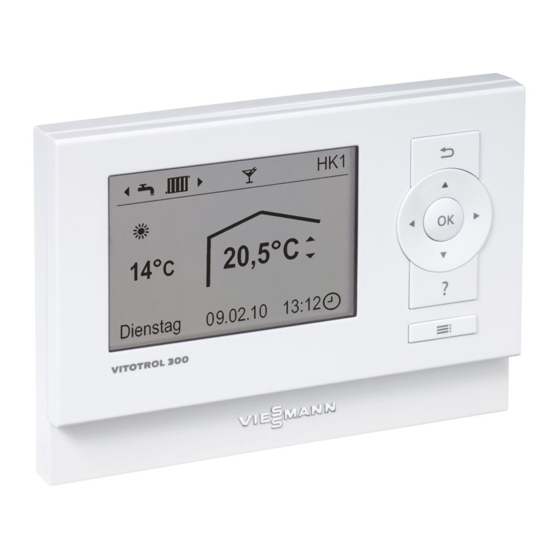
- Page 1 VIESMANN Installation and service instructions for contractors Vitotrol 300A Remote control, part no. 7438 364 VITOTROL 300A Please keep safe. 5458 093 GB 3/2010...
-
Page 2: Safety Instructions
Safety instructions Safety instructions Please follow these safety instructions closely to prevent accidents and mate- rial losses. Safety instructions explained ■ all current safety regulations as defined by DIN, EN, DVGW, TRGI, Danger TRF, VDE and all locally applicable This symbol warns against the standards, risk of injury. - Page 3 ■ When using gas as fuel, also close the For replacements, use only orig- main gas shut-off valve and safeguard inal spare parts from Viessmann against unauthorised reopening. or those which are approved by ■ Isolate the system from the power sup- Viessmann.
-
Page 4: Table Of Contents
Index Index Installation instructions Installation sequence Installation location....................Installing and connecting the Vitotrol 300A............Connecting several remote control units.............. Fitting the programming unit................. Removing the programming unit (if required)............10 Service instructions Commissioning Configuring the remote control................11 Specification....................... 12... -
Page 5: Installation Sequence
Installation sequence Installation location ■ Weather-compensated mode Do not install further controllers in this Installation in any room. room. Open any thermostatic radiator ■ Operation with room temperature- valves fully. dependent control – On an internal wall in the living Note space, at a height of approx. -
Page 6: Installing And Connecting The Vitotrol 300A
Installation sequence Installing and connecting the Vitotrol 300A Please note Before beginning work, touch Electronic modules can be dam- earthed objects, such as heating aged by electrostatic dis- or water pipes, to discharge static charges. loads. Connection Note Two-core cable with a cross-section of at Never route the cable to the remote con- least 0.75 mm;... -
Page 7: Connecting Several Remote Control Units
Installation sequence Installing and connecting the Vitotrol 300A (cont.) 7 6 5 4 3 2 1 A Vitotrol 300A D Separate room temperature sensor (accessory) B 2 or 3-pole plug aVG (to the control unit or the KM BUS distributor) - Page 8 Installation sequence Connecting several remote control units (cont.) Version 1 15 m 15 m A To the control unit or to the KM BUS B Vitotrol distributor (see connection diagram C Socket (on site) on page 7) ■ On-site connection via socket: ■...
-
Page 9: Fitting The Programming Unit
Installation sequence Fitting the programming unit Please note Do not insert batteries into the The remote control is supplied battery compartment. with power by the control unit. -
Page 10: Removing The Programming Unit (If Required)
Installation sequence Removing the programming unit (if required) -
Page 11: Commissioning
8. OK as confirmation. with one Vitotrol 300A; alternatively one The operating state of the heating Vitotrol 300A can be employed for each system is transferred. A running bar heating circuit in a single heating sys- appears in the display. This process tem. -
Page 12: Specification
Specification Specification Power supply via KM BUS Power consumption 0.5 W Protection class IP rating IP 30 to EN 60529; ensure through appropriate design and installation Permissible ambient temperature ■ during operation 0 to +40 °C −20 to +65 °C ■... -
Page 13: Parts List
Parts list Parts list When ordering spare parts Parts not shown Quote part no. 7438 364 and the pos. no. 080 Installation and service instructions of the part (as per this parts list). 081 Operating instructions Obtain standard parts from your local supplier. - Page 16 Viessmann Werke GmbH&Co KG Viessmann Limited D-35107 Allendorf Hortonwood 30, Telford Telephone: +49 6452 70-0 Shropshire, TF1 7YP, GB Fax: +49 6452 70-2780 Telephone: +44 1952 675000 www.viessmann.com Fax: +44 1952 675040 E-mail: info-uk@viessmann.com...
Need help?
Do you have a question about the VITOTROL 300A and is the answer not in the manual?
Questions and answers