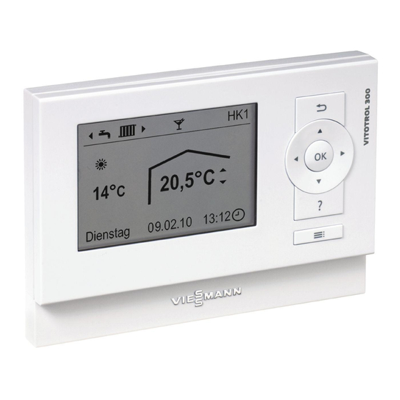
Summary of Contents for Viessmann Vitotrol 300-A
- Page 1 VIESMANN Installation and service instructions for contractors Vitotrol 300-A Remote control For applicability, see the last page VITOTROL 300-A Please keep safe. 5784 752 GB 8/2016...
- Page 2 Hot surfaces can cause burns. Replace faulty components only with genuine ■ Before maintenance and service work, switch Viessmann spare parts. OFF the appliance and let it cool down. Never touch hot surfaces on the boiler, burner, ■ flue system or pipework.
-
Page 3: Safety Instructions
For replacements, use only original spare parts supplied or approved by Viessmann. Safety instructions for operating the system If you smell gas Condensate Danger... - Page 4 Disposal of packaging ................Symbols ....................Intended use ..................Installation sequence Installation location ................Installing and connecting the Vitotrol 300-A .......... Connecting several remote control units ..........Installing and removing the programming unit ........Commissioning Configuring the remote control .............. 10 Troubleshooting Fault display ...................
-
Page 5: Disposal Of Packaging
Please dispose of packaging waste in line with statu- tory regulations. DE: Use the disposal system organised by Viessmann. AT: Use the ARA statutory disposal system (Altstoff Recycling Austria AG, licence number 5766). CH: Packaging waste is disposed of by the HVAC contractor. - Page 6 Install and operate the appliance as intended, in con- junction with the electronic control units and controllers for the Viessmann heat and power generators designed for this system. Also take account of the rele- vant installation, service and operating instructions. In particular, observe the current and voltage specifica- tions for connections and hook-ups.
-
Page 7: Installation Location
Not near heat sources (direct sunlight, fireplace, sor, part no. 7438 537. – TV set, etc.) Installing and connecting the Vitotrol 300-A Please note Electronic assemblies can be damaged by elec- trostatic discharge. Prior to commencing any work, touch earthed objects such as heating or water pipes to dis- charge static loads. -
Page 8: Connecting Several Remote Control Units
Separate room temperature sensor NTC 10 k Ω KM-BUS connection (accessories) Note When replacing the Vitotrol 300-A, also replace the room temperature sensor. Connecting several remote control units Vitotrol 200-A and Vitotrol 300-A can be connected jointly to a Vitotronic control unit. - Page 9 To the control unit (see connection diagram on To the control unit (see connection diagram on page 8) page 8) Vitotrol 300-A Vitotrol 300-A KM-BUS distributor or on-site junction box KM-BUS distributor or on-site junction box Max. total length of all KM-BUS cables 50 m.
- Page 10 Vitoligno solid fuel boilers, up to 4 heating circuits can be controlled. A Vitovent ventilation system can also be operated. Up to two Vitotrol 300-A can be connected to one Vitotronic. 1. Switch ON the power supply at the control unit.
-
Page 11: Troubleshooting
Troubleshooting Fault display In the event of a fault, the symbol flashes on the dis- play and "Fault" is shown. Call up the cause of the fault by pressing OK. Fault Fault Acknowledge with Fig. 7 Some faults are displayed as plain text. For an explanation of the fault codes, see instal- lation and service instructions for the respective control unit. - Page 12 Parts lists (cont.) 0002 0003 0001 0004 0005 0006 Fig. 9...
- Page 13 Parts lists (cont.) Pos. Part 0001 Programming unit 0002 Wall mounting base 0003 Cover, wiring chamber 0004 Fixing materials and plugs 0005 Installation instructions 0006 Operating instructions...
- Page 14 Specification Specification Power supply Via KM-BUS Power consumption Protection class IP rating IP 30 Permissible ambient temperature During operation °C 0 to 40 ■ During storage and transport °C 20 to +65 °C − ■ Set room temperature setting range °C 3 to 37...
-
Page 15: Declaration Of Conformity
Certificates Declaration of conformity Vitotrol 300-A We, Viessmann Werke GmbH & Co. KG, D-35107 Allendorf, declare as sole responsible body that the named product complies with the provisions of the following directives and regulations: 2014/30/EU EMC Directive 2014/35/EU Low Voltage Directive... - Page 16 Applicability Serial No.: 7571013 7571231 Viessmann Werke GmbH & Co. KG Viessmann Limited D-35107 Allendorf Hortonwood 30, Telford Telephone: +49 6452 70-0 Shropshire, TF1 7YP, GB Fax: +49 6452 70-2780 Telephone: +44 1952 675000 www.viessmann.com Fax: +44 1952 675040 E-mail: info-uk@viessmann.com...


Need help?
Do you have a question about the Vitotrol 300-A and is the answer not in the manual?
Questions and answers