Table of Contents
Advertisement
Quick Links
HELIOS SINGLE BOARD COMPUTER
Revision
Date
B
5/15/2009
B1-8
2/23/2012
B9
1/4/2016
FOR TECHNICAL SUPPORT
PLEASE CONTACT:
support@diamondsystems.com
PC/104 SBC with Vortex Processor
and Integrated Data Acquisition
Rev B9: January 2016
Comment
Major update
Minor corrections; removed 300MHz models
Updated power consumption
Copyright 2016
Diamond Systems Corporation
555 Ellis Street
Mountain View, CA 94043 USA
Tel 1-650-810-2500
Fax 1-650-810-2525
www.diamondsystems.com
Advertisement
Table of Contents

Related Manuals for Diamond Systems HELIOS

Summary of Contents for Diamond Systems HELIOS
- Page 1 HELIOS SINGLE BOARD COMPUTER PC/104 SBC with Vortex Processor and Integrated Data Acquisition Rev B9: January 2016 Revision Date Comment 5/15/2009 Major update B1-8 2/23/2012 Minor corrections; removed 300MHz models 1/4/2016 Updated power consumption Copyright 2016 FOR TECHNICAL SUPPORT Diamond Systems Corporation...
-
Page 2: Table Of Contents
12.3 Console Redirection to a Serial Port ......................34 13. Data Acquisition Circuit Overview ....................... 35 14. Data Acquisition I/O Register Map ....................... 36 14.1 Overview ..............................36 14.2 Register Write Functions ..........................37 14.3 Register Read Functions ..........................38 www.diamondsystems.com Helios User Manual Rev B9 Page 2... - Page 3 25.2 ACC-CFEXT CompactFlash Adapter ......................80 26. Panel I/O Board .............................. 81 27. I/O Cables ............................... 82 28. Specifications ..............................83 28.1 Processor Section (All Models) ........................83 28.2 Data Acquisition Section (HLV800-256AV Only) ..................84 www.diamondsystems.com Helios User Manual Rev B9 Page 3...
-
Page 4: Important Safe Handling Information
Always store this product in ESD-protective packaging when not in use. Safe Handling Precautions The Helios board contains a high number of I/O connectors with connection to sensitive electronic components. This creates many opportunities for accidental damage during handling, installation and connection to other equipment. - Page 5 The same situation can occur when pulling a ribbon cable off of a pin header. If the pins are bent too severely, bending them back can cause them to weaken unacceptably or even break, and the connector must be replaced. www.diamondsystems.com Helios User Manual Rev B9 Page 5...
-
Page 6: Introduction
2. INTRODUCTION Helios is an embedded single board computer in the PC/104 small form factor based on the DMP Vortex86DX family of all-in-one 486 processors. Helios integrates a complete embedded PC plus a full analog and digital data acquisition circuit into a single board. It is available in several models with different features:... - Page 7 Interrupt and DMA performance is supported on the ISA bus. Up to 4 I/O boards can be installed on the ISA bus on Helios, depending on the loading characteristics of the add-on modules.
-
Page 8: Functional Block Diagram
3. FUNCTIONAL BLOCK DIAGRAM Functional Block Diagram www.diamondsystems.com Helios User Manual Rev B9 Page 8... -
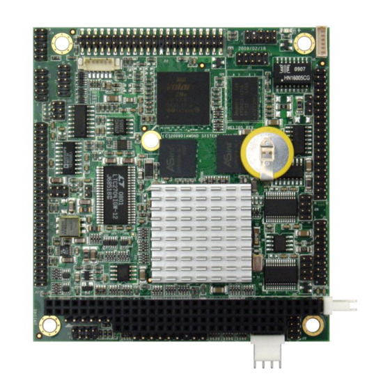
Page 9: Board Diagram
4. BOARD DIAGRAM The diagram below shows the board layout, including connectors, jumper blocks and mounting holes. 2.462 IN 0.080 IN Helios Board Layout www.diamondsystems.com Helios User Manual Rev B9 Page 9... -
Page 10: Connector And Jumper Lists
Jtag for data acquisition FPGA (factory use) Panel power input Jtag for Processor / BIOS flash (factory use) 5.2 Configuration Jumpers Jumper Description LCD backlight DAQ interrupt configuration Not used COM1 RS-422/RS-485 configuration COM2 RS-422/RS-485 configuration www.diamondsystems.com Helios User Manual Rev B9 Page 10... -
Page 11: I/O Connectors
+12V, -12V, and -5V inputs are provided for convenience and are passed onto the PC/104 bus but are not used by Helios. The +3.3V input is passed through to the LCD connector and may be used to power an attached LCD. -
Page 12: Serial Ports (J8)
Connector type: Standard 2mm dual row straight pin header with gold flash plating Serial ports are typically used with DB9 connectors. The PC / Helios side of the connection uses a male version of the connector and uses the DTE (data terminal equipment) pin assignment. The connecting cable will use a female version of the connector with DCE (data communications equipment) pinout. -
Page 13: Ps/2 Mouse And Keyboard (J3)
6.6 USB (J15, J16) Helios features four USB 2.0 ports on 2 pin headers. Connector J15 interfaces to USB port 0/1 and connector J16 interfaces to USB ports 2/3. USB 2.0 provides a 480Mbps maximum data transfer rate. The shield pin on each connector is tied to system ground. -
Page 14: Ethernet (J11)
Signals used for monitor detection (DDC1 specification) Pin missing to match key pin in cable to prevent incorrect connection Connector type: Standard 2mm dual row straight pin header with gold flash plating www.diamondsystems.com Helios User Manual Rev B9 Page 14... -
Page 15: Lvds Lcd Interface (J13, Bottom Side Of Board)
6.9 LVDS LCD Interface (J13, bottom side of board) Connector J13 is used to connect an LVDS LCD. Helios does not support TTL LCDs. If needed, the LCD backlight can be connected to connector J9. Ground / D3+, depending on video chip... -
Page 16: Ide (J12)
The IDE connector is a standard notebook hard drive type 2x22 (44-pin) 2mm-pitch pin header. It mates with Diamond Systems’ cable number 6981004, and may be used to connect up to 2 IDE drives (hard disks, CD- ROMs, or flashdisk modules). An IDE flashdisk may also be installed on this connector to provide rugged, wide temperature solid state storage up to 4GB. -
Page 17: Digital I/O (J7)
GPIO port 0 from Vortex CPU DIO E7-0 GPIO port 1 from Vortex CPU Connected to main +5V supply Ground Digital ground Connector type: Standard 2mm dual row straight pin header with gold flash plating www.diamondsystems.com Helios User Manual Rev B9 Page 17... -
Page 18: Data Acquisition (J17)
6.14 Data Acquisition (J17) Connector J17 is provided for the AV model with data acquisition. Diamond Systems cable number 6981163 provides a 50-pin connector with both 2mm and .1” pitch connectors for use with this connector. DIO A0 DIO A1... -
Page 19: Miscellaneous (J14)
Connector type: Standard 2mm dual row straight pin header with gold flash plating 6.16 Autocalibration (J19) Connector J19 is used on the Helios AV model for factory calibration of the analog I/O circuit. A precision voltmeter is connected to this connector to measure the on-board references during the calibration process. -
Page 20: Pc/104 Isa Bus (J1, J2)
DRQ7 SD12 SA15 DRQ3 SD13 SA14 DACK1- MASTER- SD14 SA13 DRQ1 Ground SD15 SA12 Refresh- Ground Key (pin cut) SA11 SYSCLK SA10 IRQ7 IRQ6 IRQ5 IRQ4 IRQ3 DACK2- BALE Ground Ground Ground www.diamondsystems.com Helios User Manual Rev B9 Page 20... -
Page 21: Configuration Jumpers
Available options are +5V from the main power supply input or +12V from the auxiliary +12V input. +12V is not used by any circuit on the Helios CPU, so it is not required to provide it on the input power connector. If +12V is needed for the LCD backlight, and the backlight is to be powered via the backlight power connector J9, then +12V must be supplied on the main power input connector along with +5V. -
Page 22: Data Acquisition Interrupt Configuration (J21)
Jumper block J21 is used to configure the data acquisition circuit interrupt selection and interrupt pull-down resistor on the AV model of Helios. Although the diagrams below show labels on the jumper block, there are no labels on the board. The orientation of the block in the diagrams matches the orientation of the jumper block when the board is rotated so that the PC/104 connector is on the lower edge (facing you). -
Page 23: Rs-422/Rs-485 Configuration (J25, J26)
RS-422 bias only RS-485 term + gnd RS-485 gnd only RS-232 Label Function 485 TERM RS-485 Tx termination resistor 422 TERM RS-422 Rx termination and bias resistors GROUND ground pin for RS-422 / RS-485 www.diamondsystems.com Helios User Manual Rev B9 Page 23... -
Page 24: System Resources
8. SYSTEM RESOURCES The table below lists the default system resources utilized by the circuits on Helios. Device I/O Address ISA IRQ ISA DMA 0x3F8 – 0x3FF – Serial Port COM1 0x2F8 – 0x2FF – Serial Port COM2 0x3E8 – 0x3EF –... -
Page 25: Video Features
Helios includes a video subsystem that provides both CRT and LCD output with several choices of resolution. The resolution is fixed in the BIOS but can be changed with a software utility provided on the Diamond Systems CD. LCD Resolution... -
Page 26: Lcd
Helios uses the more popular LVDS (low-voltage differential signaling) format. If you are planning to use a TTL LCD with Helios, you will need to use a small adapter board that converts LVDS to TTL. Many such boards are available from suppliers. -
Page 27: Changing The Lcd / Crt Resolution
The enable signal on J9 controls power to the backlight. It is controlled by Helios GPIO signal Port 3 Bit 6. The LCD display can also be enabled or disabled by using GPIO signal Port 3 Bit 5. To control these settings in software, do the following: 1. -
Page 28: Modifying The Bios With A New Lcd Resolution
1. PC with Windows XP 2. MMTOOL software 3. Existing Helios BIOS image 4. Helios LCD BIOS extension files 5. Bootable device with DOS or FREEDOS, such as an IDE flashdisk or USB memory stick 6. SPIFLASH software Instructions for MMTOOL software: 1. -
Page 29: Updating The Bios With Spiflash Software
DOS 8-character naming convention. spiflash u <filename.rom> 5. SPIFLASH will automatically reprogram the Helios SBC’s BIOS image and provide a progress indicator. The program will indicate successful completion of the process, which should take about 10 seconds. -
Page 30: Installation And Configuration
10.2 Boot Device Options Helios can boot to an IDE device, a USB device, or the on-board 2MB virtual floppy drive. Helios has a single IDE channel that can support up to two devices simultaneously (Master and Slave). IDE devices connect to J12, which is a 44-pin, laptop style IDE connector. -
Page 31: Bios Functions
11.4 Built-In Flash Drive with FreeDOS Helios contains a built-in 8Mbit (2MB) flash memory pre-loaded with a ready to run copy of FreeDOS. This flash memory can be set up as a bootable A: drive. About 1.5MB of space is available for file storage. -
Page 32: Blue Led
11.6 Blue LED Helios contains a programmable blue LED along the top edge of the board, near the VGA connector. This LED is controlled by the Vortex processor GPIO port 3 bit 4. It can be turned on and off in the BIOS and in software. The LED is on by default. -
Page 33: Serial Ports And System Console
12. SERIAL PORTS AND SYSTEM CONSOLE 12.1 Overview Helios contains four 16550-style asynchronous serial ports derived from the Vortex86 processor. Each port has 16-character transmit and receive FIFOs and is capable of transmitting at speeds of 9600, 19.2K, 38.4K, 57.6K, or 115.2Kbaud. -
Page 34: Console Redirection To A Serial Port
These settings can be changed in the BIOS as described below. A serial port on another PC can be connected to the console serial port on Helios with a null modem cable. A null modem cable has a DB9 female connector at each end and swaps the TX and RX signals from one end to the other, so that two DTE devices can communicate directly with each other. -
Page 35: Data Acquisition Circuit Overview
13. DATA ACQUISITION CIRCUIT OVERVIEW Helios contains a data acquisition subsystem consisting of A/D, D/A, digital I/O, and counter/timer features. This subsystem is equivalent to a complete add-on data acquisition PC/104 module such as the Diamond Systems DMM-16-AT. The A/D section includes a 16-bit A/D converter, 16 analog input channels, and a 2048-sample FIFO. Input ranges are programmable, and the maximum sampling rate is 250KHz. -
Page 36: Data Acquisition I/O Register Map
14.1 Overview The data acquisition circuit on the AV model of Helios uses an FPGA which is attached to the ISA bus. It is accessible via a 16-byte window in ISA I/O space. It can be enabled or disabled in the BIOS. Select Chipset, then South Bridge Configuration, then GPCS. -
Page 37: Register Write Functions
EEPROM Access Key Register Page 2: Expanded FIFO and AD/DA Control EXFIFO ADPOL ADSD DAUR DACH1 DACH0 DAPOL DAG1 DAG0 DA15 DA14 DA13 DA12 DA11 DA10 (*) During Enhanced FIFO mode (EXFIFO=1) www.diamondsystems.com Helios User Manual Rev B9 Page 37... -
Page 38: Register Read Functions
Page 1: AutoCal Control TDBUSY EEBUSY CALMUX Not Used Page 2: Expanded FIFO and AD/DA Control EXFIFO DAUR DACH1 DACH0 ADPOL ADSD DASIZE DAPOL DAG1 DAG0 D/A Simultaneous Update (*) During Enhanced FIFO mode (EXFIFO=1) www.diamondsystems.com Helios User Manual Rev B9 Page 38... -
Page 39: I/O Map Detailed Description
If the FIFO is not empty, this register returns the LSB of the A/D value stored at the current FIFO pointer. If the FIFO is empty, reading from this register returns 0. AD7 – 0 A/D data bits 7 - 0; AD0 is the LSB. www.diamondsystems.com Helios User Manual Rev B9 Page 39... - Page 40 It is not required that the High channel be greater or equal to the Low channel. A setting of Low=14 and High=2 is valid. In this case the channel sequence is 14, 15, 0, 1, 2, 14, 15, … www.diamondsystems.com Helios User Manual Rev B9 Page 40...
- Page 41 If overflow occurs, then you must either reduce the sample rate or increase the efficiency of your interrupt routine and/or operating system. SCANEN, ADG1-0 Readback of scan enable and A/D gain settings written to base+2 www.diamondsystems.com Helios User Manual Rev B9 Page 41...
- Page 42 When AINTE = 0. the A/D is triggered only by writing a 1 to the ADSTART bit at base+0. When AINTE = 1, the A/D cannot be triggered by setting the ADSTART bit at base+0. Instead the A/D trigger comes from the hardware source selected by the ADCLK bit. www.diamondsystems.com Helios User Manual Rev B9 Page 42...
- Page 43 Enhanced Mode: EXFIFO = 1 (See Register Description for page 2, base+12) Bit No. Name FD07 FD06 FD05 FD04 FD03 FD02 FD01 FD00 FD07-00 FIFO depth. Readback of the lower 8 bits of the number of A/D values currently stored in the FIFO. www.diamondsystems.com Helios User Manual Rev B9 Page 43...
- Page 44 0 = the FIFO is less than half full. 1 = the FIFO is half full or greater. FIFO Empty. 0 = the FIFO still has data. 1 = the FIFO is empty. www.diamondsystems.com Helios User Manual Rev B9 Page 44...
- Page 45 When port B is in input mode, this register will read back the logic levels on pins DIO B7-0, and writing to this register will have no effect. The direction of port B is controlled by the DIO control register at base+11. www.diamondsystems.com Helios User Manual Rev B9 Page 45...
- Page 46 If DIOCTR = 0, then the direction of these pins is controlled by DIRCH. DAMODE 16/12-bit DAC mode. This bit should only be set for custom models of Helios with a 16-bit DAC installed. This bit defines where the high bits of the D/A value are to be found when loading the D/A.
-
Page 47: Counter/Timer Control
1, this register is ignored. When reading from this register, the associated byte of the most recent Latch command will be returned. The value returned is NOT the value written to this register. www.diamondsystems.com Helios User Manual Rev B9 Page 47... - Page 48 REV0 This register is used to indicate the board ID and data acquisition FPGA revision. The initial production version of Helios reads back ID code 0x70. The code will increment by 1 each time a new revision is released. REV3-0 Revision code.
-
Page 49: Autocalibration Control
TDACWR TrimDAC Write. Writing 1 to this bit will initiate a transfer to the TrimDAC addressed by the register at page 1, base+13. (used in the autocalibration process). If both EE_EN and TDACWR are set to ‘1’ then TDACWR is ignored. www.diamondsystems.com Helios User Manual Rev B9 Page 49... - Page 50 PG1 and PG0 (base+1 bits 1-0) in order to get access to the EEPROM. This helps prevent accidental corruption of the EEPROM contents. Once the key value is written, access to the EEPROM remains enabled until the page bits are changed. www.diamondsystems.com Helios User Manual Rev B9 Page 50...
-
Page 51: Expanded Fifo And Ad/Da Control
DARCH1-0 DA channel for selected range. If DAUR=0, these bits are ignored. If DAUR=1, these bits determine which D/A channel will have the range programmed according to DAPOL and DAG1-0. DAPOL D/A polarity configuration DAG1-0 D/A converter output range www.diamondsystems.com Helios User Manual Rev B9 Page 51... - Page 52 Bit No. Name DASIZE DAPOL DASIZE This bit indicates the resolution of the D/A converter installed. The standard models of Helios all use a 12-bit DAC. 12-bit DAC 16-bit DAC DAC MSB – 16-Bit Enhanced Mode Page 2 Base + 15 Write Bit No.
-
Page 53: Analog-To-Digital Input Ranges And Resolution
15.1 Overview The Helios AV model data acquisition circuit uses a 16-bit A/D converter. The full range of numerical values for a 16-bit number is 0 - 65535. However, the A/D converter uses two’s complement notation, so the A/D value is communicated as a signed integer, ranging from -32768 to +32767. -
Page 54: Performing An A/D Conversion
A/D circuit settling indicator: 0 = circuit is idle, conversion can start; 1 = circuit is busy, must wait ADPOL A/D polarity configuration: 0 = Bipolar, 1 = Unipolar ADSD A/D single-ended / differential configuration: 0 = Single-ended, 1 = Differential www.diamondsystems.com Helios User Manual Rev B9 Page 54... -
Page 55: Select The Input Channel
A/D if AINTE = 0 (interrupts are disabled). When AINTE = 1, the A/D can only be triggered by the on-board counter/timer or an external signal. This protects against accidental triggering by software during a long-running interrupt-based acquisition process. outp(base,0x80); www.diamondsystems.com Helios User Manual Rev B9 Page 55... -
Page 56: Wait For The Conversion To Finish
Only conversion to input voltage is described. However, you can combine both transformations into a single formula if desired. To convert the A/D value to the corresponding input voltage, use the following formulas. www.diamondsystems.com Helios User Manual Rev B9 Page 56... -
Page 57: Conversion Formula For Bipolar Input Ranges
A/D Code Symbolic Formula 0-5V Range -32768 0.0000V -32767 1 LSB (V / 65536) 0.000076V / 2 - 1 LSB 2.4999V 2.5000V / 2 + 1 LSB 2.5001V 32767 - 1 LSB 4.9999V www.diamondsystems.com Helios User Manual Rev B9 Page 57... -
Page 58: A/D Scan, Interrupt And Fifo Operation
When an interrupt is pending, the IRQ line will be driven high. When no interrupt is pending, the board will release the IRQ line and it will be pulled low by the pull-down resistor configured with J21. It is possible for Helios to generate interrupts from up to 3 sources simultaneously. - Page 59 The interrupt software behavior given in the table describes the operation of the Diamond Systems Universal Driver software. If you write your own software or interrupt routine you should conform to the described behavior for optimum results.
-
Page 60: Digital-To-Analog Output Ranges And Resolution
18. DIGITAL-TO-ANALOG OUTPUT RANGES AND RESOLUTION 18.1 Description Helios uses a 4-channel D/A converter (DAC) to provide four analog voltage outputs. The standard configuration uses a 12-bit DAC, however a 16-bit DAC is available as a special ordering option. A 12-bit DAC can generate output voltages with the precision of a 12-bit binary number. -
Page 61: D/A Conversion Formulas And Tables
The formulas below explain how to convert between D/A codes and output voltages. The D/A code is always an integer. For a 12-bit D/A (Standard models of Helios), the D/A code ranges between 0 and 4095 (2 -1). For a 16- bit D/A (custom option), the D/A code ranges between 0 and 65535 (2 -1). -
Page 62: D/A Conversion Formulas For Bipolar Output Ranges
12-Bit Output Voltage Output Voltage for D/A Code Symbolic Formula 10V Range -10.0000V + 1 LSB -9.9951V 2047 -1 LSB -0.0049V 2048 0.0000V 2049 +1 LSB 0.0049V 4095 - 1 LSB 9.9951V www.diamondsystems.com Helios User Manual Rev B9 Page 62... -
Page 63: Generating An Analog Output
DACH1-0 D/A channel to receive current data in DA11-0 or DA15-0 DAMODE 16/12-bit DAC mode. This bit should only be set for custom models of Helios with a 16-bit DAC DASIM D/A simultaneous mode: 0 = immediate update with new data, 1 = simultaneous mode... -
Page 64: Set Simultaneous Update Mode And/Or Dac Resolution
The standard model of Helios uses a 12-bit DAC, and no resolution setting is required. If a 16-bit DAC is installed in a custom configuration of Helios, the DAMODE bit must be set to tell the FPGA where the DAC MSB data is found when loading the DAC. -
Page 65: Update The D/A
Any channel which has not been changed since it was last updated will simply reload the same value and therefore will remain steady. outp(base+1, 2); // select page 2 a = inp(base+15); // read register to update all DACs www.diamondsystems.com Helios User Manual Rev B9 Page 65... -
Page 66: Analog Circuit Calibration
20. ANALOG CIRCUIT CALIBRATION The Helios data acquisition circuit contains an advanced autocalibration circuit that can maintain the accuracy of both A/D and D/A circuits to within the specified tolerances regardless of time and temperature. Autocalibration is supported in the Diamond Systems Universal Driver software included with the board. -
Page 67: Digital I/O Ports
21. DIGITAL I/O PORTS Helios has two groups of digital I/O ports and one digital interrupt circuit: 3 8-bit ports named A, B, and C are included in the data acquisition circuit on the AV model and are available on connector J17 on that model. -
Page 68: Vortex Processor Digital I/O Ports
The Vortex processor has an integrated digital I/O (GPIO) circuit with 5 8-bit ports. Two of them (ports 0 and 1) are available for use as general purpose digital I/O on Helios and are identified as ports D and E. These ports are accessible on I/O connector J7. -
Page 69: Digital Interrupts
When an interrupt is pending, the IRQ line will be driven high. When no interrupt is pending, the board will release the IRQ line and it will be pulled low by the pull-down resistor configured with J21. It is possible for Helios to generate interrupts from up to 3 sources simultaneously. -
Page 70: Counter/Timer Operation
22. COUNTER/TIMER OPERATION The AV model of Helios with data acquisition contains two counter/timers that provide various timing functions on the board for A/D timing and user applications. These counters are controlled with registers in the on-board data acquisition controller FPGA. Base+4 includes counter configuration bits, and base+11 contains the configuration bit DIOCTR, which controls 4 dual-function I/O pins on the data acquisition connector J17. -
Page 71: Counter 0 - A/D Sample Rate Control
The control register at page 0 Base+15 is used to load and clear the counter and to enable and disable counting. The optional gate (when DIOCTR=1) can be enabled and disabled, and the counter value can be latched for reading. www.diamondsystems.com Helios User Manual Rev B9 Page 71... -
Page 72: Counter 1 - Counting, Totalizing, And Interrupt Functions
IRQ line and it will be pulled low by the pull-down resistor configured with J21. It is possible for Helios to generate interrupts from up to 3 sources simultaneously. Thus clearing one interrupt will not necessarily cause the IRQ line to go low. It will only go low when all 3 circuits are inactive or have no interrupts pending. -
Page 73: Command Sequences
22.3 Command Sequences Diamond Systems provides free Universal Driver software to control the counter/timers on Helios. The information in this section is intended as a guide for programmers writing their own code, instead of using the driver, and to give a better understanding of the counter/timer operation. - Page 74 2. Read the data (optional). The value is returned in 3 bytes, low, middle, and high (2 bytes for counter 1). low=inp(base+12); low=inp(base+12); middle=inp(base+13); high=inp(base+13); high=inp(base+14); 3. Clear the counter. outp(base+15,0x01); outp(base+15,0x81); www.diamondsystems.com Helios User Manual Rev B9 Page 74...
-
Page 75: Watchdog Timer
Bit No. Name WDTEN WDTEN Watchdog timer enable: Disable WDT operation; timeout event will not occur. Enable WDT operation; timeout event will occur if WDT is not retriggered before it times out. www.diamondsystems.com Helios User Manual Rev B9 Page 75... - Page 76 Write/Read WDT Timeout Indicator Bit No. Name WDTTO WDTTO When this bit is 1, a timeout occurred on the watchdog timer. Write a 1 to this bit to reset the timeout indicator. www.diamondsystems.com Helios User Manual Rev B9 Page 76...
-
Page 77: Flashdisk Module
The flashdisk module installs directly on the IDE connector, J12, and is held down with a spacer and two screws a mounting hole on the board. The mounting hardware is included with the flashdisk in hardware kit 6801008. The Helios SBC may already include the mounting spacer, in which case only the top side screw is required. www.diamondsystems.com... -
Page 78: Bios Flashdisk Configuration
24.4 BIOS FlashDisk Configuration To configure the Helios SBC to work with the flashdisk module, enter the BIOS by pressing DEL during startup. Select the Main menu, and then select IDE Primary Master. Enter the settings shown in the following table. Exit the BIOS and save the change. -
Page 79: Mass Storage Accessories
To connect a flashdisk + IDE notebook hard drive to the Helios, connect one end of cable 6981004 to the SBC, and attach the other two connectors to the ACC-IDEEXT and the hard drive. -
Page 80: Acc-Cfext Compactflash Adapter
Helios SBC. It includes a 44-wire cable, part number 6981004. This cable connects from the IDE connector on Helios to the 44-pin connector on the adapter. Both IDE signals and +5V are provided to the board via the 44-wire cable. -
Page 81: Panel I/O Board
Data acquisition from Helios model HLV800-256AV The panel I/O board may be used together with the Helios SBC in an “open frame” configuration, or the assembly can be installed in a Pandora enclosure to create a complete, cable-free, compact industrial computer. Pandora is available in multiple lengths to allow the installation of PC/104 add-on modules below the Helios SBC to provide additional functionality in the system. -
Page 82: I/O Cables
27. I/O CABLES Diamond Systems offers Cable Kit C-HLV-KIT with cables for all I/O connectors on the board except the LCD and backlight. Some cables are also available separately. Helios Cables Kit C-HLV-KIT Photo No. Cable Part No. Description Helios Connector... -
Page 83: Specifications
5.4W typical 7.3W maximum 3.550” W x 3.775” H Dimensions PC/104 compliant Weight 2.5oz / 71g 3.1oz / 88g MTBF 65,535 hours Operating temperature -40ºC to +85ºC / -40ºC to +71ºC RoHS Compliant www.diamondsystems.com Helios User Manual Rev B9 Page 83... -
Page 84: Data Acquisition Section (Hlv800-256Av Only)
8mA max High: -12mA max High: -8mA max Counter/Timers A/D pacer clock 24 bit down counter 10MHz, 1MHz, or external clock input General purpose 16-bit down counter 10MHz, 100KHz, or external clock input www.diamondsystems.com Helios User Manual Rev B9 Page 84...
Need help?
Do you have a question about the HELIOS and is the answer not in the manual?
Questions and answers