
Related Manuals for Uponor UponorControl System


Summary of Contents for Uponor UponorControl System
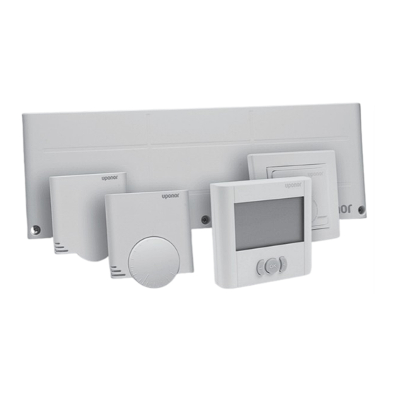
- Page 1 INDOOR CLIMATE UPONOR CONTROL SYSTEM W I R E D Installation and Operation Manual 01 | 2011...
-
Page 2: Table Of Contents
Installing thermostats ......... 9.13 CAL – Calibration ..........Selecting locations for thermostats....9.14 OFF – Standby mode ........Installing Uponor Thermostats T-36 and T-38. 9.15 Lock mode ............5.2.1 Opening the thermostats ......... UPONOR CONTROL SYSTEM WIRED - INSTALLATION AND OPERATION MANUAL... - Page 3 10.11 Menu tree ............Maintenance ..........11.1 Manual preventive maintenance ...... 11.2 Automatic preventive maintenance....11.3 Corrective maintenance........11.3.1 Fallback mode..........11.3.2 Resetting the controller ........11.4 Troubleshooting..........Technical data ..........UPONOR CONTROL SYSTEM WIRED - INSTALLATION AND OPERATION MANUAL...
-
Page 4: Copyright And Disclaimer
While Uponor has made efforts to ensure that the Manual is accurate, Uponor does not guarantee or warrant the accuracy of the information contained herein. Uponor reserves the right to... -
Page 5: Preface
We cannot accept any responsibility for damage or breakdown that can result from ignoring these instructions! Power WARNING! The Uponor system uses 50 Hz, 230 V AC power. In case of emergency, immediately disconnect the power. Technical constraints CAUTION To avoid interference, keep installation/data cables away from power cables of more than 50 V. -
Page 6: Description
Designed for maximum comfort, the thermostats T-37 and T-38 communicate with the controller by non-polarized two wired cables. It is possible to mix the different types of Uponor wired For example, the maximum limitation can protect a thermostats in the same installation. -
Page 7: Uponor Control System Wired Components
Uponor Controller, 6 Channels C-33 Wired Pos. Uponor designation Description The Uponor Controller, 6 Channels C-33 Wired controls up to 6 Uponor Controller, 6 6-channel controller thermostats and 8 actuators connected to the hydraulic system of Channels C-33 Wired the installation. -
Page 8: Thermostats
Can be set to permanent override mode • Hidden reset 3.3.3 Timer • Powered by controller (no batteries) Uponor Timer I-36 can be connected to control the system. Display shows: Uponor Timer I-36 wired • Setpoint temperature Main characteristics: •... -
Page 9: Uponor Actuators
3.3.4 Uponor Actuators Uponor actuators are mounted on top of the valves of the manifolds When the thermostat senses that the temperature has fallen below the setpoint, the controller sends a signal to the actuator to open the valve. The indicator window on the actuator turns bright. -
Page 10: Installing The Uponor Control System Wired
Installing the Uponor Control System Wired Installation procedure 2. Check that the connectors and switches are easily accessible. Uponor recommends that you follow the steps described below CAUTION to achieve the best possible installation: The Uponor Controllers C-33 and C-35 must be Section Description mounted horizontally. -
Page 11: Auto Linking
01. All actuators on rows 01 to 04 are controlled from the same thermostat. The next thermostat, #05, controls the actuators on rows 05 to 11 and thermostat #12 controls the actuator on row 12. UPONOR CONTROL SYSTEM WIRED - INSTALLATION AND OPERATION MANUAL... -
Page 12: Connecting Thermostats And Actuators To Uponor Controller C-35
Heating Cooling Controller C-33 Timer control zone 2 No cooling for this room Uponor Controller C-33 can only be used for heating. One to six thermostats and one to eight actuators can be connected to this NOTE! controller. The two wires from the thermostat are non-polarized. -
Page 13: Connecting A Heating-Cooling Switch
(B)on the upper part of the lid. 4.3.6 Connecting a heating–cooling switch If the installation is equipped with a cooling unit, the Uponor Control System Wired can be run through a heating–cooling switch. The controller heating–cooling input operates with the... -
Page 14: Connection Examples
4.4.5 Uponor Controller C-35 with four thermostats, timer and heating–cooling switch, page 15 4.4.1 Uponor Controller C-33 A connection example of Uponor Controller C-33 is shown in the figure below. • Thermostat #01 controls the actuators on channels 01a and •... -
Page 15: Uponor Controller C-35 With Four Thermostats And Without Timer
4.4.4 Uponor Controller C-35 with four thermostats and timer A connection example of Uponor Controller C-35 using four thermostats is shown in the figure below. NOTE! When connecting thermostats and actuators to the Uponor Controller, the auto-linking rules must always be followed strictly. - Page 16 If a Uponor Timer I-36 is connected to the Uponor Controller C- 35 and the system is operating in cooling mode, then zone 1 and Timer zone 2 will automatically be combined to a single zone.
-
Page 17: Connecting The Controller To Ac Power
2. Ensure that the 230 V AC compartment of the controller is closed and the fixing screw is tightened. 3. Connect the power cable to a 230 V AC wall socket. UPONOR CONTROL SYSTEM WIRED - INSTALLATION AND OPERATION MANUAL... -
Page 18: Installing Thermostats
2. Ensure that the thermostat is away from direct solar 5.2.2 Mounting the thermostats radiation. Uponor Thermostats T-36 and T-38 are delivered in kits including 3. Ensure that the thermostat will not be heated through the screws and plugs. wall from sunshine. -
Page 19: Connecting Thermostat To Controller
It is possible to connect a floor sensor or a remote indoor sensor to Uponor Thermostats T-36 and T-38. 5.3.2 Mounting the thermostats Uponor Thermostat T-34 is delivered in a kit including screws and 1. Insert the two wires of the sensor cable into the connector plugs. terminals labelled 3 and 4. -
Page 20: Installing Uponor Thermostats T-35, T-33, And
5.4.2 Mounting thermostats onto a wall The Uponor thermostats are delivered in kits including screws and wall plugs. The Uponor thermostats can be mounted either directly onto a wall or using a 60 mm European wall box. See figure below. -
Page 21: Connecting Optional Floor Sensor
1. Use a cross-headed screwdriver to set the potentiometer. See figure below. 5.4.4 Connecting optional floor sensor Uponor Thermostats T-33 and T-37 allow a floor sensor to be fitted to the system. The temperatures thus measured ensure a more efficient management of the system. Wiring the floor sensor 1. -
Page 22: Installing Uponor Timer I-36 For
4.3 Connecting components to controller, page Connecting an optional dry contact It is possible to connect a dry contact input to Uponor Timer I-36, for example a Uponor Remote Access Module R-56. 1. Insert the two wires of the dry contact cable into the connector terminals labelled 3 and 4. -
Page 23: Finishing Installation
3. Close the covers of the controller and the thermostats. Fill in the “Installation report” on the centre pages of booklet. 5. Give the manual and all information about the system to the user. UPONOR CONTROL SYSTEM WIRED - INSTALLATION AND OPERATION MANUAL... -
Page 24: Operating Uponor Control System Wired
Operating Uponor Control System Wired The Uponor Control System Wired controls the floor heating/ cooling installation according to customer needs. Temperatures are adjusted with thermostats located in each room. Principle of operation As soon as the temperature measured at a thermostat is lower... - Page 25 1. Carefully remove the dial using a small, flat-bladed screwdriver. 2. Set the minimum temperature limit with the blue stopper (A). 3. Set the maximum temperature limit with the red stopper (B). UPONOR CONTROL SYSTEM WIRED - INSTALLATION AND OPERATION MANUAL...
-
Page 26: Operating Digital Thermostats
0 or 5 Used with suitcase icon, see pos. B above. Temperature unit, shown when the character group A shows a temperature UPONOR CONTROL SYSTEM WIRED - INSTALLATION AND OPERATION MANUAL... -
Page 27: Operating Buttons
ECO or comfort, as defined by the • Heating or cooling icon depending on system working mode programming. • ECO or comfort mode icon depending on system working mode UPONOR CONTROL SYSTEM WIRED - INSTALLATION AND OPERATION MANUAL... -
Page 28: Parameter And Mode Settings Menu
9. Press the + and - buttons to change the setting. There are three alternatives: 10. Press OK to confirm the setting. • Monday till Friday, default setting • Monday till Saturday UPONOR CONTROL SYSTEM WIRED - INSTALLATION AND OPERATION MANUAL... -
Page 29: Hol - Holiday Mode (T-38 Only)
9.10 BAL – Balancing mode. • Set the clock to the time for the first comfort/economy If RFT regulation mode is selected, the next regulation changeover. setting, is displayed. UPONOR CONTROL SYSTEM WIRED - INSTALLATION AND OPERATION MANUAL... -
Page 30: Bal - Balancing Mode
Default setting: 4 °C Entering standby mode Setting range: 0 – 11 °C 1. Press OK to confirm the standby mode. Setting accuracy: 0.5 °C The standby icon and the room temperature is displayed. UPONOR CONTROL SYSTEM WIRED - INSTALLATION AND OPERATION MANUAL... -
Page 31: Lock Mode
Other displayed information remains and the thermostat operates as set-up. Exiting lock mode 1. Press and hold the + and - buttons simultaneuously for three seconds. The lock icon disappears. UPONOR CONTROL SYSTEM WIRED - INSTALLATION AND OPERATION MANUAL... -
Page 32: Menu Trees
9.16 Menu trees The following sections show the menu trees for Uponor Thermostats T-36 and T-38 9.16.1 Uponor Thermostat T-36 Run mode, see section 9.4, page 27 Regulation choices, see section, see section 9.9, page 29 Room sensor regulation, see section 9.9, page 29... -
Page 33: Operating Uponor Timer I-36
Operating Uponor Timer I-36 Uponor Timer I-36 has a screen with a number of icons and Pos. Icon Description symbols for displaying messages. Manual override. For example forced Below the screen there are three buttons for operating Uponor comfort or economy mode. -
Page 34: Operating Buttons
Remote system controlled forced economy mode Forced economy mode ina zone can be set from a remote external system such as the Uponor R-56 SMS module. Then the empty 10.4 Run mode house and hand icon are flashing. In this case it is not possible to cancel the forced mode from the timer. -
Page 35: Prg - Programming
10. Press and hold the OK key for 3 seconds to select the default 2. If required, press the + or - button to change zone. schedule. 3. Press OK to start the programming. UPONOR CONTROL SYSTEM WIRED - INSTALLATION AND OPERATION MANUAL... -
Page 36: Hol - Holiday Mode
1 d flashing, designating the number of days the holiday The lock icon disappears. mode is active 2. Press the + and - buttons to set the number of days the holiday mode shall be active. UPONOR CONTROL SYSTEM WIRED - INSTALLATION AND OPERATION MANUAL... -
Page 37: Menu Tree
10.11 Menu tree The structure below illustrates the menu tree of Uponor Timer I-36. Run mode, see section 10.4, page 34 Clock settings, see section, see section 10.6, page 34 Year, see section, see section 10.6, page 34 Month, see section, see section 10.6, page 34... -
Page 38: Maintenance
Do not use any detergents to clean the Uponor System components. 11.2 Automatic preventive maintenance Uponor Control System Wired is fitted with an automatic exercise function. This function consists of a test run designed to prevent the pump and actuators from seizing up due to inactivity. - Page 39 2. Check that the actuators are connected to the same zone in the controller as on the manifold. 3. Check that thermostatsare connected to the correct zone in the controller. UPONOR CONTROL SYSTEM WIRED - INSTALLATION AND OPERATION MANUAL...
- Page 40 1. To return to nomal scheduling will not follow the into econony mode by a remote mode the dry contact input specified time scheduling system must be opened again by the remote system. UPONOR CONTROL SYSTEM WIRED - INSTALLATION AND OPERATION MANUAL...
-
Page 41: Technical Data
C-33/C-35 to heating/cooling relay — 20 m 0.2 – 1.5 mm C-33/C-35 to timer — 0.2 – 1.5 mm C-33/C-35 to dew-point sensor module — 20 m 0.2 – 1.5 mm UPONOR CONTROL SYSTEM WIRED - INSTALLATION AND OPERATION MANUAL... - Page 42 Connectors for dew-point sensor unit • Red = Heating mode Connectors for 1–14 actuators • Green = Heating–cooling mode Connectors for 1–12 thermostats • Off = Power off 230 V AC compartment C-35 wiring diagram UPONOR CONTROL SYSTEM WIRED - INSTALLATION AND OPERATION MANUAL...
- Page 43 Pos. Description Connectors for 1–8 actuators Power indicator Connectors for 1–6 thermostats • Red = Power on (heating mode) 230 V AC compartment • Off = Power off C-33 wiring diagram UPONOR CONTROL SYSTEM WIRED - INSTALLATION AND OPERATION MANUAL...
- Page 44 Installation report Controller No. Channels Rooms Floor sensor Relay +24 V DC 230 V AC Pump Timer UPONOR CONTROL SYSTEM WIRED - INSTALLATION AND OPERATION MANUAL...
- Page 45 UPONOR CONTROL SYSTEM WIRED - INSTALLATION AND OPERATION MANUAL...
- Page 46 Uponor Housing Solutions Ltd. Snapethorpe House Rugby Road, Tel. +44 1455 550 355 Lutterworth Leicestershire LE17 4HN Fax +44 1455 550 366 www.uponorhousingsolutions.co.uk Uponor reserves the right to change specifications without prior notice, in keeping with our policy of continuous improvement and development.
Need help?
Do you have a question about the UponorControl System and is the answer not in the manual?
Questions and answers