Table of Contents
Advertisement
Quick Links
Advertisement
Table of Contents

Related Manuals for Fuling Inverter DZB200 Series

Summary of Contents for Fuling Inverter DZB200 Series
- Page 1 www.yusto.ru info@yusto.ru...
-
Page 2: Table Of Contents
目 录 Chapter 1 Safety and Cautions Chapter 2 Product Introduction Chapter 3 Mechanical and Electrical Installation Chapter 4 Operation and Display Chapter 5 Function Parameters List Chapter 6 Parameter Description F0 Basic Function Parameters F1 Motor Parameters F2 Input and Output Terminal Function Parameters F3 Human Machine Interface Parameters F4 Application Function Parameters F5 Protection Pa rameters... - Page 3 DZB Series Preface Preface Thank you for choosing Series high-performance AC Motor Drives. DZB200&300 Series are manufactured by adopting high-quality components, material and incorporating the latest microprocessor technology availa ble. Ge tting Started This manual will be helpful in the installation, parameter setting, troubleshooting, and daily maintenance of the AC motor drives.
-
Page 4: Chapter 1 Safety And Cautions
DZB Series DZB Series Chapter 1 Safety and Cautions Chapter 1 Safety and Cautions Chapter 1 Safety and Cautions Note Safety Definition ★ Do not connect the input terminals with the output termina ls (U, V, W), otherw ise the inverter There are two kinds of safety cautions in the manual: may be damaged! ★... - Page 5 DZB Series DZB Series Chapter 1 Safety and Cautions Chapter 1 Safety and Cautions Cautions Note 1. Check the Insulation of the Motor When the motor is used for the first time, or reused after storing for a long time, or in regular checkup, ★...
-
Page 6: Chapter 2 Product Introduction
DZB Series DZB Series Chapter 1 Safety and Cautions Chapter 2 Product Introduction 11. Special Usages The user can consult our company if he wants to use another method instead of the recommended Chapter 2 Product Introduction connecting method provided in the manual, such as shared DC bus. 12. -
Page 7: Chapter 3 Mechanical And Electrical Installation
DZB Series DZB Series Chapter 2 Product Introduction Chapter 3 Mechanical and Electric al Installation Chapter 3 Mechanical and Electrical Installation 2.2 Nameplate Information Mechanical Installation Nameplate 1. Installation Environment 1) Ambient temperature: Ambient temperature influences the inverter life grea tly, so it should be w ithin ℃... -
Page 8: Electrical Installation
DZB Series DZB Series Cha pter 3 Mechanical and Electrical Installation Chapter 3 Mechanical and Electric al Installation Electrical Installation 2. Wiring Diagram of Peripheral Equipment 1.Applicable devices and recommendable wiring of main circuit: INPUT(RST) Wire Size(mm ) Pow er Supply Applicable MODEL Motor... -
Page 9: Basic Wiring Diagram
DZB Series DZB Series Cha pter 3 Mechanical and Electrical Installation Chapter 3 Mechanical and Electric al Installation 3. Basic Wiring Diagram 4. Main Circuit Terminals and Wiring Users must conne ct wires according to the following circuit diagram show n below. Danger DC Link Reactor (option) ★... - Page 10 DZB Series DZB Series Cha pter 3 Mechanical and Electrical Installation Chapter 3 Mechanical and Electric al Installation ( ) 、 ( ): 3 ) N ote s o n C on t rol Te r m in al s: C.Brake resistor terminals of BR+ The brake resistor terminal is effective only for the inverte r of 15kW or below and has a built-in brake A) Analog input terminal:...
- Page 11 DZB Series DZB Series Cha pter 3 Mechanical and Electrical Installation Chapter 3 Mechanical and Electric al Installation 2) Reducing the disturbance to the inverter from other equipment Note: Pay attention to the polarity of the diode as shown in the figure 3-8. Otherwise if the digital The re lay, contactor or electronic -magnetic braking device will disturb t he invert er.
-
Page 12: Chapter 4 Operation And Display
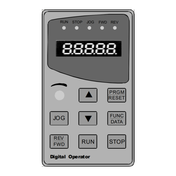
DZB Series DZB Series Chapter 4 Operation and Display Chapter 4 Operatio n and Display Chapter 4 Digital Keypad Operation Used to start the AC drive operation. Description of the Digital Keypad This key has no effect when the drive is set to terminal run. ●... - Page 13 DZB Series DZB Series Chapter 4 Operation and Display Chapter 4 Operatio n and Display Explanation of Displayed Messages on Stop status r ( efer to F3.05): Note: When operating 3-level menu, pressing PRG or DATA can return to second level menu. The difference is: pressing DATA will save the parameters and return to second le vel menu and then shift to the next function c ode, while pressing PRG will return to second level menu without saving the Displayed...
-
Page 14: Chapter 5 Function Parameters List
Stage 3 menu. : Note This function is invalid for DZB200 Series. 1. The column of function table is described as follows: Before running the inverter that has sele cted the vector control mode, accurate motor nameplate “... -
Page 15: F0 Basic Function Parameters
DZB Series DZB Series Chapter 5 Function Parameters List Chapter 5 Function Parameters List Default Default Function Modifi Serial Function Modifi Serial Setting Range Setting Range Name Name Code Value cation Code Value cation : 2 Invalid durin g dece lerati on F0 Basic Function Parameters :... -
Page 16: F2 Input And Output Terminal Function Parameters
DZB0 Series DZB Series Chapter 5 Function Parameters List Chapter 5 Function Parameters List Default Default Function Modifi Serial Function Modifi Serial Setting Range Setting Range Name Name Code Value cation Code Value cation Mutual inductance of S5 Termi na l Function 6:Fr ee run stop Set by ~... -
Page 17: F3 Human Machine Interface Parameters
DZB Series DZB Series Chapter 5 Function Parameters List Chapter 5 Function Parameters List Default Default Function Modifi Serial Function Modifi Serial Setting Range Setting Range Name Name Code Value cation Code Value cation : CI upper limit 0 Keypad control valid ~... -
Page 18: F4 Application Function Parameters
DZB Series DZB Series Chapter 5 Function Parameters List Chapter 5 Function Parameters List Default Default Function Modifi Serial Function Modifi Serial Setting Range Setting Range Name Name Code Value cation Code Value cation Input terminal status 18 :Communication fa ult(E01 8) Output terminal status 19 :Current detect e rror( E0 15 ) PID setpoint... -
Page 19: F5 Protection Parameters
DZB Series DZB Series Chapter 5 Function Parameters List Chapter 5 Function Parameters List Default Default Function Modifi Serial Function Modifi Serial Setting Range Setting Range Name Name Code Value cation Code Value cation ~ ※ Multi-S peed 2 ~ ※... -
Page 20: Chapter 6 Parameter Description
DZB Series DZB Series Chapter 5 Function Parameters List Chapter 6 Parameter Description Chapter 6 Parameter Description Default Function Modifi Serial Setting Range Name Code Value cation F0 Basic Function Parameters ( ) 3:No check N,8,2 for RTU Function Default Setting Range Name (... - Page 21 DZB Series DZB Series Chapter 6 Parameter Description Chapter 6 Parameter Description : 0: Valid, and the inverter memorizes when power down. Able to set up frequency command, and memorize 6 Remote communication this set frequency when the inverter is power down. When the power is back,automatically combine it with The frequency command is given in the communication mode by upper position machine.For details, “...
- Page 22 DZB Series DZB Series Chapter 6 Parameter Description Chapter 6 Parameter Description Output frequency f Function Default Setting Range Name Code Value Set by m a x Carrie r frequency setti ng ~ F0.11 1.0 15 .0kHz model s et Carrier Electr onmagnetic Cacophony,...
- Page 23 DZB Series DZB Series Chapter 6 Parameter Description Chapter 6 Parameter Description starting frequency, inverter doe s not operate and is at stand-by state. The starting frequency value is not Functio n Default Setting Range Name Cod e Value restricted by the lower limit frequency. :...
- Page 24 DZB Series DZB Series Chapter 6 Parameter Description Chapter 6 Parameter Description 0: Terminal command invalid when power on. Inverter will not run if it detect operating command terminal O u tp u t F r e q u e n c y f is valid.
- Page 25 DZB Series DZB Series Chapter 6 Parameter Description Chapter 6 Parameter Description Functio n Default Function Default Setting Range Setting Range Name Name Cod e Code Value Value Set by ~ Ω Speed loop prop ortional F1.0 6 Motor sta tor resistance 0.0 01 65.535 ~...
- Page 26 DZB Series DZB Series Chapter 6 Parameter Description Chapter 6 Parameter Description Output Voltage (V) Func tio n Default Setting Range Name Cod e Value ~ Upper torque l imit setting 200.0%(inverter rated current) F1.1 9 15 0.0% The setting 100.0% is corresponding to the rated output current. (...
- Page 27 DZB Series DZB Series Chapter 6 Parameter Description Chapter 6 Parameter Description Func tio n Defau lt Setting Range Name When the frequency is set by external terminal, modify the Code Value Frequency freque ncy up and down command. When the frequency F2.01 S1 Terminal Function Selec tion 0~25...
- Page 28 DZB Series DZB Series Chapter 6 Parameter Description Chapter 6 Parameter Description This parameter defines four different control modes which controls the inverter operation through 3: Three-wire control, separate Enable from direction. At this mode EN is the Enable terminal, SW1 or external terminals.
- Page 29 DZB Series DZB Series Chapter 6 Parameter Description Chapter 6 Parameter Description Above function codes define the relationship betwee n analog input voltage and the setting value that Function Default Setting Range Name Cod e Value analog input is corresponding to. When the analog input voltage exceeds the range of the set maximum or Mo1output selection F2.19 0~10...
- Page 30 DZB Series DZB Series Chapter 6 Parameter Description Chapter 6 Parameter Description F3 Human Machine Interface Par ameters Func tio n Default Setting Range Name Cod e Value ~ F2.23 AO L ower li mi t 0.0 % 1 00.0 % 0.0% Function Default...
- Page 31 DZB Series DZB Series Chapter 6 Parameter Description Chapter 6 Parameter Description , Option: setting paramete r=the sum total of display code for example: Func tio n Default Setting Range Name Cod e Value require to display at operation status:Output current,Running speed,Output power 4+16+32=52, then :...
- Page 32 DZB Series DZB Series Chapter 6 Parameter Description Chapter 6 Parameter Description Func tio n Default Function Default Setting Range Setting Range Name N ame Cod e Code Value Value The output frequency when current fault Jogging frequency ~ Operating freq uency at F4.02 0.00 F0.04 5.0 0Hz...
- Page 33 DZB Series DZB Series Chapter 6 Parameter Description Chapter 6 Parameter Description Traverse frequency function is suitable to industries such as textile, fi ber and so on, and t o applications which require traversing and winding functions. Output fre quency Traverse frequency function means that the inverter output frequency is traversing up and down around FDT delay the set frequency.
- Page 34 DZB Series DZB Series Chapter 6 Parameter Description Chapter 6 Parameter Description When frequency source is chosen to be PID, i.e. F0.03 is chosen to be 5, these group functions are active. Func tio n Default Setting Range Name Cod e Value This parameter is to determine the assignment channel of the proce ss PID target value.
- Page 35 DZB Series DZB Series Chapter 6 Parameter Description Chapter 6 Parameter Description Proportional gain (Kp): determines the adjusting strength of PID adjustor. The bigger the P, the bigger Function Default Setting Range N ame Code Value the adjusting strength is. This parameter being 100 mea ns that when the difference between the PID S ampling c yc le time (T) ~...
- Page 36 DZB Series DZB Series Chapter 6 Parameter Description Chapter 6 Parameter Description 、 、 1 S2 S3 Relati onship between multi-speed and S terminal s Func tio n Default Setting Range Name Cod e Value Current segment of multi-sp eed control Multi -Spe ed 0 ~...
- Page 37 DZB Series DZB Series Chapter 6 Parameter Description Chapter 6 Parameter Description Func tio n Default Function Default Setting Range Setting Range Name N ame Cod e Code Value Value ~ : 20.0% 120.0% 0 pr ohibit Motor Overload F5.01 10 0.0% Over-voltage (mo tor rate d current)
- Page 38 DZB Series DZB Series Chapter 6 Parameter Description Chapter 6 Parameter Description Function Default Setting Range N ame Code Output curr ent Value Data pattern ( ) F6.02 0:No chec k N,8,1 for RTU Auto limit current level ( ) 1:Odd check E,8,1 for RTU (...
- Page 39 DZB Series DZB Series Chapter 6 Parameter Description Chapter 6 Parameter Description Function Default DATA Frame:8-E-1 Setting Range N ame Code Value Commun icatio n Start Even Stop ~ F6.03 0 200 ms bit0 bit1 bit2 bit3 bit4 bit5 bit6 bit7 respon se dela y 8-data bits Re sponse delay: means the interval time from the end of data receive to transmitting response data to...
-
Page 40: Chapter 7 Fault Diagnosis And Countermeasures
DZB Series DZB Series Cha pter 7 Fault Diagnosis and Countermeasures Chapter 7 Fault Diagnosis and Countermeasures Chapter 7 Fault Diagnosis and Countermeasures 1. Und er voltage of DC Bus(E001) DZB300 has 25 pieces of alarm information and protection functions in total. Once the fault occurs, Transient powe r cut exists or not motor driver inverter reset the protection function starts, the inverter stops inputting, the fault relay contact point is activated, and the... - Page 41 DZB Series DZB Series Cha pter 7 Fault Diagnosis and Countermeasures Chapter 7 Fault Diagnosis and Countermeasures 3. Over voltage during running(E003) 5. Ove r current during deceleration(E005) Check if the output loop of the m otor driver Adjust the voltage within Remove the peripheral fault The input voltage is too high or not inverter has the earthing or short circuit...
- Page 42 DZB Series DZB Series Cha pter 7 Fault Diagnosis and Countermeasures Chapter 7 Fault Diagnosis and Countermeasures 7. Motor Over Load(E007) 10. Over voltage during deceleration(E00A) Adjust the voltage within The motor protection parameter The input voltage is too high or not Correctly set up the parameter normal range F5.01 setting is suitable or not...
- Page 43 DZB Series DZB Series Cha pter 7 Fault Diagnosis and Countermeasures Chapter 7 Fault Diagnosis and Countermeasures 13. EEPROM read-write failure(E00F) 16. Current Inspection Circuit Failure(E015) Whether it is normal after the C hange Hall device C heck if Hall device is normal main control board fault renewal of the main control board Check if the drive board is normal...
-
Page 44: Chapter 8 Quality Guarantee
DZB Series DZB Series Chapter 8 Quality Guarantee Appendix A Standard Specifications Appendix A: Standard Specifications Chapter 8 Quality Guarantee Quality guarantees of our products is transacted as the fo llowing rules and regulations: 1.1 Technical Spe cification 8.1 Responsibility of manufac turer: Ser ies DZB300 DZB200... - Page 45 DZB Series DZB Series Appendix A Standard Specifications Appendix A Standard Specifications 1.2 AC220VSeries Rating: Series DZB300 DZB200 Item Specification pre-set frequency;operate frequenc y; output current;motor speed;input voltage; LCD Display output voltage;input/output terminals'status;fault information,etc Operation/Stop,FWD/ REV,Funct ion indication,etc LED Status indication Exteral meter display (...
-
Page 46: Appendix B Serial Communications
DZB Series DZB Series Appendix B Serial Communications Appendix B Serial Co mmunications Appendix Communication Protocol In the RTU mode, format for each byte is as follows: Coding system: Eight-bit binary notation, hexadecimal 0-9, A~F, and each 8-bit frame field includes two The DZB300 inverter provides RS232/RS485 communication ports, and adopts the standard ModBus hexadecimal characters. - Page 47 DZB Series DZB Series Appendix B Serial Communications Appendix B Serial Co mmunications The information of a frame should be transmitted in consecutive data streams. If there is an interval ASCII frame standard structure over 1.5 bytes before the completion of the transmission of the entire frame, the rec eiving device will ' : '(0x 3A)...
- Page 48 DZB Series DZB Series Appendix B Serial Communications Appendix B Serial Co mmunications RTU Response Message of the Slave ASCII Response Message of the Slave ‘:' START T1-T2-T3-T4 (tra nsmission time of 3.5 bytes) S TART ‘0' ADDR ADDR ‘1' ‘0' Higher bits of byte number ‘3'...
- Page 49 DZB Series DZB Series Appendix B Serial Communications Appendix B Serial Co mmunications ASCII Response Message of the Slave CRC CHK lower bit CRC CHK higher bit ‘:' S TART T1-T2-T3-T4 (tra nsmission time of 3.5 bytes) ‘0' ADDR Response M essage of the Slave ‘2' ‘0' START...
- Page 50 DZB Series DZB Series Appendix B Serial Communications Appendix B Serial Co mmunications 6.3.2 Cyclical Redundancy Check (CRC): 6.4 Definition of Communication Data Ad dress The RTU frame format is used. The frame includes frame error det ection field calculated on the basis of This part is the defini tion of the communication data addre ss, used to control inverter operation, and CRC.
- Page 51 DZB Series DZB Series Appendix B Serial Communications Appendix B Serial Co mmunications Address Address Function Description Data Meaning Function Description Dat a Meaning Definition Feature Definition Feature : Communication setting range (-10000~10000) 0000H Not fault Note: the communication setting is the :...
-
Page 52: Appendix C Dimensions
DZB Series DZB Series Appendix B Serial Communications Appendix C Dimensions A SC I I : Fault Response Message of the Slave A p p e n d i x C D i m e n s i o ns ‘:' START Type 1:Plastic Frame... -
Page 53: Appendix D Accessories List
DZB Series DZB Series Appendix C Dimensions Appendix D Accessories List : A p p e n d i xD A c c e s s o r ies L i s t Dimension form: ( ) Dimensions mm Applicable 1.All Braking Resistors &... - Page 54 DZB Series Appendix D Accessories List 2 . S tan d a r d E x te nsio n Ca bl e : Le n g t h Mo d e l ne t w o rk c a b le c o m p an y na me 3 .
Need help?
Do you have a question about the DZB200 Series and is the answer not in the manual?
Questions and answers