
Related Manuals for Fuling Inverter DZB200 Series

Summary of Contents for Fuling Inverter DZB200 Series
- Page 1 5 / 1 4 / 2 0 1 8 F u l i n g I n v e r t e r U s e r M a n u a l - s l i d e p d f . c o m h t t p : / / s l i d e p d f .
-
Page 2: Table Of Contents
5 / 1 4 / 2 0 1 8 F u l i n g I n v e r t e r U s e r M a n u a l - s l i d e p d f . c o m 目... - Page 3 DZB Series Preface 5 / 1 4 / 2 0 1 8 F u l i n g I n v e r t e r U s e r M a n u a l - s l i d e p d f . c o m Preface T ha nk y ou f or c ho os in g Series...
- Page 4 5 / 1 4 / 2 0 1 8 F u l i n g I n v e r t e r U s e r M a n u a l - s l i d e p d f . c o m h t t p : / / s l i d e p d f .
- Page 5 5 / 1 4 / 2 0 1 8 F u l i n g I n v e r t e r U s e r M a n u a l - s l i d e p d f . c o m h t t p : / / s l i d e p d f .
- Page 6 5 / 1 4 / 2 0 1 8 F u l i n g I n v e r t e r U s e r M a n u a l - s l i d e p d f . c o m h t t p : / / s l i d e p d f .
-
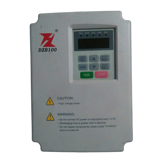
Page 7: Chapter 2 Product Introduction
DZB Series DZB Series Chapter 2 Product Introduction Chapter 3 Mechanical and Electrical Installation 5 / 1 4 / 2 0 1 8 F u l i n g I n v e r t e r U s e r M a n u a l - s l i d e p d f . c o m Chapter 3 Mechanical and Electrical Installation 2.2 Nameplate Information Mechanical Installation... -
Page 8: Chapter 3 Mechanical And Electrical Installation
DZB Series DZB Series Chapter 3 Mechanical and Electrical Installation Chapter 3 Mechanical and Electrical Installation 5 / 1 4 / 2 0 1 8 F u l i n g I n v e r t e r U s e r M a n u a l - s l i d e p d f . c o m Electrical Installation 2. - Page 9 5 / 1 4 / 2 0 1 8 F u l i n g I n v e r t e r U s e r M a n u a l - s l i d e p d f . c o m h t t p : / / s l i d e p d f .
- Page 10 5 / 1 4 / 2 0 1 8 F u l i n g I n v e r t e r U s e r M a n u a l - s l i d e p d f . c o m h t t p : / / s l i d e p d f .
- Page 11 5 / 1 4 / 2 0 1 8 F u l i n g I n v e r t e r U s e r M a n u a l - s l i d e p d f . c o m h t t p : / / s l i d e p d f .
-
Page 12: Chapter 4 Operation And Display
DZB Series DZB Series Chapter 4 Operation and Display Chapter 4 Operation and Display 5 / 1 4 / 2 0 1 8 F u l i n g I n v e r t e r U s e r M a n u a l - s l i d e p d f . c o m Chapter 4 Digital Keypad Operation Used tos tart theAC drive operation. - Page 13 5 / 1 4 / 2 0 1 8 F u l i n g I n v e r t e r U s e r M a n u a l - s l i d e p d f . c o m h t t p : / / s l i d e p d f .
- Page 14 5 / 1 4 / 2 0 1 8 F u l i n g I n v e r t e r U s e r M a n u a l - s l i d e p d f . c o m h t t p : / / s l i d e p d f .
-
Page 15: Chapter 5 Function Parameters List
DZB Series DZB Series Chapter 5 Function Parameters List Chapter 5 Function Parameters List 5 / 1 4 / 2 0 1 8 F u l i n g I n v e r t e r U s e r M a n u a l - s l i d e p d f . c o m Function Default Function... - Page 16 DZB0 Series DZB Series Chapter 5 Function Parameters List Chapter 5 Function Parameters List 5 / 1 4 / 2 0 1 8 F u l i n g I n v e r t e r U s e r M a n u a l - s l i d e p d f . c o m Function Default Function...
- Page 17 DZB Series DZB Series Chapter 5 Function Parameters List Chapter 5 Function Parameters List 5 / 1 4 / 2 0 1 8 F u l i n g I n v e r t e r U s e r M a n u a l - s l i d e p d f . c o m Function Default Modifi...
- Page 18 Chapter 5 Function Parameters List Chapter 5 Function Parameters List 5 / 1 4 / 2 0 1 8 F u l i n g I n v e r t e r U s e r M a n u a l - s l i d e p d f . c o m Function Default Modifi...
- Page 19 5 / 1 4 / 2 0 1 8 F u l i n g I n v e r t e r U s e r M a n u a l - s l i d e p d f . c o m Default Default Function...
- Page 20 5 / 1 4 / 2 0 1 8 F u l i n g I n v e r t e r U s e r M a n u a l - s l i d e p d f . c o m h t t p : / / s l i d e p d f .
- Page 21 5 / 1 4 / 2 0 1 8 F u l i n g I n v e r t e r U s e r M a n u a l - s l i d e p d f . c o m h t t p : / / s l i d e p d f .
- Page 22 5 / 1 4 / 2 0 1 8 F u l i n g I n v e r t e r U s e r M a n u a l - s l i d e p d f . c o m h t t p : / / s l i d e p d f .
-
Page 23: Chapter 6 Parameter Description
5 / 1 4 / 2 0 1 8 F u l i n g I n v e r t e r U s e r M a n u a l - s l i d e p d f . c o m ... -
Page 24: F1 Motor Parameters
0: Terminal command invalid when power on. Inverter will not run if it detect operating command termi nal O u tp u t F r e q u e n c y f 5 / 1 4 / 2 0 1 8 F u l i n g I n v e r t e r U s e r M a n u a l - s l i d e p d f . - Page 25 5 / 1 4 / 2 0 1 8 F u l i n g I n v e r t e r U s e r M a n u a l - s l i d e p d f . c o m ...
-
Page 26: F2 Input And Output Terminal Function Parameters
Output Voltage (V) Default Function Setting Range Name Code Value 5 / 1 4 / 2 0 1 8 F u l i n g I n v e r t e r U s e r M a n u a l - s l i d e p d f . c o m Upper torque limit setting ~... - Page 27 5 / 1 4 / 2 0 1 8 F u l i n g I n v e r t e r U s e r M a n u a l - s l i d e p d f . c o m ...
- Page 28 This parameter defines four different contr ol modes which controls the inverter operation through 3: Three-wire control, separate Enable from direction. At this mode EN is the Enable terminal, SW1 or external terminals. SW2 define operating command and control direction at the same time. Stop command is defined by SW2. 5 / 1 4 / 2 0 1 8 F u l i n g I n v e r t e r U s e r M a n u a l - s l i d e p d f .
- Page 29 5 / 1 4 / 2 0 1 8 F u l i n g I n v e r t e r U s e r M a n u a l - s l i d e p d f . c o m ...
-
Page 30: F3 Human Machine Interface Parameters
F3 Human Machine Interface Parameters Function Default Setting Range Name Code Value 5 / 1 4 / 2 0 1 8 F u l i n g I n v e r t e r U s e r M a n u a l - s l i d e p d f . c o m F2.23 AO Lower li mi t 0.0 % 100.0 %... - Page 31 , Option: setting parameter=the sum total of display code for example: Function Default Setting Range Name Code Value require to display at operation status:Output current,Running speed,Output power 4+16+32=52, then 0 external keyboard preferential : 5 / 1 4 / 2 0 1 8 F u l i n g I n v e r t e r U s e r M a n u a l - s l i d e p d f .
- Page 32 5 / 1 4 / 2 0 1 8 F u l i n g I n v e r t e r U s e r M a n u a l - s l i d e p d f . c o m ...
- Page 33 Traverse frequency function is suitable to industries such as textile, fiber and so on, and t o applications which require traversing and winding functions. Output frequency 5 / 1 4 / 2 0 1 8 Traverse frequency function means that the inverter output frequency is traversing up an d down around F u l i n g I n v e r t e r U s e r M a n u a l - s l i d e p d f .
- Page 34 5 / 1 4 / 2 0 1 8 F u l i n g I n v e r t e r U s e r M a n u a l - s l i d e p d f . c o m h t t p : / / s l i d e p d f .
- Page 35 5 / 1 4 / 2 0 1 8 F u l i n g I n v e r t e r U s e r M a n u a l - s l i d e p d f . c o m ...
-
Page 36: F5 Protection Parameters
Function Default Setting Range Name Code Value Current segment of multi-speed control Multi-Speed 0 ~ F4.29 - 100. 0 100. 0% 0.0% 5 / 1 4 / 2 0 1 8 F u l i n g I n v e r t e r U s e r M a n u a l - s l i d e p d f . c o m O F F O F F Multi-Speed 0... - Page 37 5 / 1 4 / 2 0 1 8 F u l i n g I n v e r t e r U s e r M a n u a l - s l i d e p d f . c o m ...
-
Page 38: F6 Communication Parameters
Name Setting Range Output current Code Value Data pattern 0: No c hec k N, 8, 1 f or RTU ( ) F6.02 Auto limit current level 5 / 1 4 / 2 0 1 8 F u l i n g I n v e r t e r U s e r M a n u a l - s l i d e p d f . c o m 1: Odd c heck E, 8, 1 f or RTU (... - Page 39 DATA Frame:8 E 1 Name Code Value Communication Start Even Stop ~ F6.03 2 00 ms bit0 bit1 bit2 b it3 bit4 bit5 bit6 bit7 response delay 5 / 1 4 / 2 0 1 8 F u l i n g I n v e r t e r U s e r M a n u a l - s l i d e p d f . c o m Response delay: means the interval t ime from the end of data receive to transmitting response dat a to 8-data bits upper level machine.
-
Page 40: Chapter 7 Fault Diagnosis And Countermeasures
5 / 1 4 / 2 0 1 8 F u l i n g I n v e r t e r U s e r M a n u a l - s l i d e p d f . c o m ... - Page 41 Check if the output loop of the motor driver Adjust the voltage within Remove the peripheral fault The input voltage is too high or not inverter has the earthing or short circuit the normal range 5 / 1 4 / 2 0 1 8 F u l i n g I n v e r t e r U s e r M a n u a l - s l i d e p d f .
- Page 42 Adjust the voltage within The motor protection parameter The input voltage is too high or not Correctly set up the parameter normal range F5.01 setting is suitable or not 5 / 1 4 / 2 0 1 8 F u l i n g I n v e r t e r U s e r M a n u a l - s l i d e p d f . c o m If there exists external forces driving the Cancel the external force or Reduce the load or...
- Page 43 Whether it is normal after the Change Hall device Check if Hall device is normal 5 / 1 4 / 2 0 1 8 main control board fault F u l i n g I n v e r t e r U s e r M a n u a l - s l i d e p d f . c o m renewal of the main control board Seek technical support Check if the drive board is normal...
-
Page 44: Appendix A Standard Specifications
5 / 1 4 / 2 0 1 8 F u l i n g I n v e r t e r U s e r M a n u a l - s l i d e p d f . c o m ... - Page 45 V olt a g e class i fi ca ti o n A C 2 20 V 0 0 1 5 0 0 2 2 0 0 3 7 0 0 1 5 0 0 2 2 0 0 3 7 0 0 7 5 0 1 1 0 0 1 5 0...
-
Page 46: Appendix B Serial Communications
5 / 1 4 / 2 0 1 8 F u l i n g I n v e r t e r U s e r M a n u a l - s l i d e p d f . c o m ... - Page 47 : (0x3A) START clear the incomplete information, and mistake that the last byte is the address field part of the new frame. Likewise, if the interval between t he start of a new frame and the previous frame is less than 3.5 bytes, Address Hi Communication address: 5 / 1 4 / 2 0 1 8...
- Page 48 START T1-T2-T3-T4 (transmission time of 3.5 bytes) START ‘0' ADDR ADDR 5 / 1 4 / 2 0 1 8 F u l i n g I n v e r t e r U s e r M a n u a l - s l i d e p d f . c o m ‘1' ‘0' Higher bits of byte number...
- Page 49 ‘:' START T1-T2-T3-T4 (transmission time of 3.5 bytes) ‘0' 5 / 1 4 / 2 0 1 8 F u l i n g I n v e r t e r U s e r M a n u a l - s l i d e p d f . c o m ADDR Response Message of the Slave ‘2'...
- Page 50 5 / 1 4 / 2 0 1 8 F u l i n g I n v e r t e r U s e r M a n u a l - s l i d e p d f . c o m ...
-
Page 51: Appendix C Dimensions
: Communication setting range (-10000~10000) 0000H Not fault Note: the communication setting is the : 0001H Password error percentage of the relative value (-100.00%~ 100.00%), which can conduct communication 5 / 1 4 / 2 0 1 8 F u l i n g I n v e r t e r U s e r M a n u a l - s l i d e p d f . c o m :... - Page 52 Type 1:P lastic Frame Type 3:St eel Frame (Standing) ‘0' ADDR ‘1' 5 / 1 4 / 2 0 1 8 F u l i n g I n v e r t e r U s e r M a n u a l - s l i d e p d f . c o m ...
- Page 53 Motor(KW) Braking Resistors DZB300B0007L2A 0.75 Applicable Motor Braking Unit Braking Model No. ofUnits Used 5 / 1 4 / 2 0 1 8 F u l i n g I n v e r t e r U s e r M a n u a l - s l i d e p d f . c o m DZB300B0015L2A 1.
- Page 54 5 / 1 4 / 2 0 1 8 F u l i n g I n v e r t e r U s e r M a n u a l - s l i d e p d f . c o m n e t wo r k c a b l e c o mp a n y n a me 3 .
Need help?
Do you have a question about the DZB200 Series and is the answer not in the manual?
Questions and answers