Table of Contents
Advertisement
SERVICE
ELECTRONIC CASH REGISTER
ELECTRONIC CASH REGISTER
ER-350 / ER-350F
ER-350FP / ER-250RF
Manual
1.
2.
3.
4.
5.
6.
7.
8.
9.
10. Schematic Diagrams
C O N T E N T S
Precaution Statements
Product Specifications
Installation and Operation
Disassembly and Assembly
Alignment and Adjustment
Troubleshooting
Exploded Views and Parts List
Block Diagram
PCB Parts List
Advertisement
Table of Contents

Subscribe to Our Youtube Channel
Related Manuals for Sam4s ER-350


Summary of Contents for Sam4s ER-350
- Page 1 ELECTRONIC CASH REGISTER ER-350 / ER-350F ER-350FP / ER-250RF SERVICE Manual ELECTRONIC CASH REGISTER C O N T E N T S Precaution Statements Product Specifications Installation and Operation Disassembly and Assembly Alignment and Adjustment Troubleshooting Exploded Views and Parts List...
- Page 2 About this Manual This service manual describes how to perform hardware service maintenance for the SAM4S ER-350 Series Electronic Cash Register. Notes Notes may appear anywhere in the manual. They describe additional information about the item. Precaution symbols . Indicates a Safety Precaution that applies to this part component.
- Page 3 This manual may not, in whole or in part, be copied, photocopied, reproduced, translated or converted to any electronic or machine readable from without prior written permission of Shin Heung Precision . SAM4S ER-350M/F SERIES Service Manual First edition. JAN 2004. V1.0 Printed in KOREA...
- Page 4 Overview of this ECR This service manual provides the technical information for many individual component systems, circuits and gives an analysis of the operations performed by the circuits. If you need more technical information, please contact our service branch or R&D center. Schematics and specifications provide the needed information for the accurate troubleshooting. All information in this manual is subject to change without prior notice.
-
Page 5: Precaution Statements
Remplacer uniquement avec une batterie du même recommended by the manufacturer. type ou d’un type équivalent recommandé par le Dispose used batteries according to the manufacturer’s constructeur. instructions. Mettre au rebut les batteries usagées conformément aux instructions du fabricant. SAM4S ER-350 SERIES... -
Page 6: Servicing Precautions
5. Use only a grounded-tip soldering iron when soldering or unsoldering ESDs. 6. Use only an anti-static solder removal device. Many solder removal devices are not rated as anti- static; these can accumulate sufficient electrical charge to damage ESDs. SAM4S ER-350 SERIES... -
Page 7: Product Specifications
Weight: 9.0 Kg Drawer Millimeters Dimensions 400(W) × 450(L) × 111(H) Weight: 12.2 Kg Body Millimeters Dimensions 400(W) × 450(L) × 266(H) Weight: 15.2 Kg Packing Carton Millimeters Dimensions 504(W) × 555(L) × 365(H) Table2-1 General Specifications SAM4S ER-350 SERIES... -
Page 8: Printer Specifications
Power Supply Voltage 5V ± 6% Encoder sensor and Reset Sensors (left and right) Reliability Not for Head life Approx. 1.5 million lines Weight Approx. 700g Table2-2 Printer Specifications This specification is subject to change without notice. SAM4S ER-350 SERIES... -
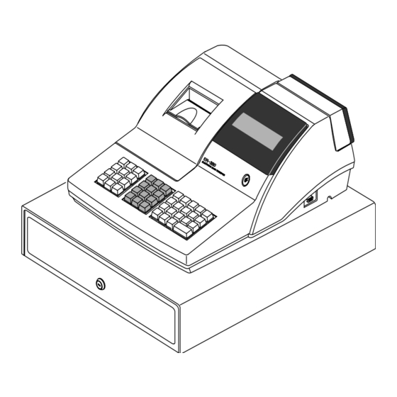
Page 9: Feature Locations
Figure2-1 Dimensions 2-2-2 Feature Locations ① Printer Cover ② Impact Dot Printer ③ Keyboard ④ Drawer ⑤ Drawer Lock Key ⑥ Mode Switch ⑦ RS-232 Serial I/F Connector ⑧ Operator Display Rear Display ⑨ Figure2-2 Feature Locations SAM4S ER-350 SERIES... -
Page 10: Communication Interfaces
PRINT SILENOID #9 PRINT SILENOID #5 PRINT COMMON LINE (+28 V) PRINT COMMON LINE (+28 V) PRINT COMMON LINE (+28 V) PRINT SILENOID #8 PRINT SILENOID #6 PRINT SILENOID #2 PRINT SILENOID #4 PRINT SILENOID #1 Table2-4. Pin Descriptions SAM4S ER-350 SERIES... -
Page 11: System Configuration
3 Installation and Operation 3-1 System Configuration 3-1-1 Interface Installation Figure 3-1. Interface Configuration Figure 3-2. Cable for Serial Port SAM4S ER-350 SERIES... - Page 12 WARNING: When connecting the keyboard to the Main PCB, make sure the membrane sheet is shaped as in Figure 3-4(a), below. If the membrane is shaped as in Figure 3-4(b), the keyboard may malfunction. Figure 3-4. Membrane Shape SAM4S ER-350 SERIES...
-
Page 13: Drawer Installation
Pay particular attention to the placement of the ribbon the Print Head. 3. After inserting the ribbon cassette, turn the knob counterclockwise again to make sure the ribbon moves freely in the cassette. Figure 3-6. Ribbon Cassette SAM4S ER-350 SERIES... - Page 14 4. Insert the paper in the notch in the Rewind Spindle as shown in Figure 3-8. Wind the Spindle three or four times to secure the paper on it. 5. If the paper is loose, wind the Rewind Spindle to tighten the paper Figure 3-7. Preparing Paper for Insertion Figure 3-8. Inserting the Paper SAM4S ER-350 SERIES...
-
Page 15: Operation
Off, Register, Manager, Clear Totals Void, Off, Register, Manager, Clear Totals, Program Void, Off, Register, Manager, Clear Totals, Program, Service Mode Table3-2 Key Function Note : The Key can be removed from the key lock in the OFF or REGISTER position. SAM4S ER-350 SERIES... -
Page 16: Initial Clear
Totals. 3-3-3 Service Mode Diagnostics The Sam4s ER-350, ER-350P, ER-350F, and ER-350FP ECR offer several diagnostic routines while in the “P mode” Each of these tests requires that the Mode key be in the “P Mode” position. 3-3-3-(a) Printer/Display Test Procedure 1. - Page 17 1. Fiscal Memory test requires that Mode Key be in the “MC Mode” position. 2. Press the 3 key. Then press the CHARGE key. The Printer prints (on a receipt) the Fiscal EPROM checksum data in the format shown below: fffc fffd fffe ffff FISCAL CHECK SUM = fe02 SAM4S ER-350 SERIES...
- Page 18 3. Installation and Operation MEMO SAM4S ER-350 SERIES...
-
Page 19: Disassembly And Assembly
1. Remove 4 screws in the Frame Assembly to separate to the Head Cover and Ribbon Frame.(Figure4-1) 2. Separate the E-Ring (RE5.0) to separate the Shaft Paper Guide from the Frame Assembly. (Figure4-2) 3. Separate the E-Ring(RE4.0) Remove the screws to separate the Paper Guide Assembly from the Frame Assembly. (Figure4-2) SAM4S ER-350 SERIES... - Page 20 8. Dissemble the Solenoid assy from the Frame Assembly. (Figure4-4) 9. After disassembling the Gear HF-2, disassemble the PP in the Lead Cam Hole. (Figure4-4) 10. Disassemble the Gear Ratchet from the “L” part of the Lead Cam. (Figure4-4) SAM4S ER-350 SERIES...
- Page 21 14. After remove the screws disassemble the spacer and the Head Pin Guide in the Head Carriage Assembly. (Figure4-6) 15. After separating the Gear HF-1. remove the SP in the right side hole in the Lead Cam. (Figure4-6) SAM4S ER-350 SERIES...
- Page 22 18. Move the Shaft Head Guide through the Head Carriage Assembly the hole “A” in the Frame Assembly(Figure4-7) Figure 4-8, Separating Lead Cam 19. After removing the Lead Cam from the Frame Assembly, remove the Poly Bearing-1.(Figure4-8) 20. Remove the PW and RE(5.0) 2PCS from the Lead Cam. (Figure4-8) SAM4S ER-350 SERIES...
- Page 23 28. Disassemble the Parallel Pin in the hole “B”, the Paper Feeder and Gear PF from the Rubber Roller. (Figure4-10) 29. After disassemble the Poly Bearing-2, disassemble the Rubber Roller in the hole “A” of the Frame Assembly. (Figure4-10) 30. Disassemble the Side Frame “L”. “R” Assembly from the Frame Fixing Plate. (Figure4-10) SAM4S ER-350 SERIES...
- Page 24 1. Position Upper Case so that connectors are within reach of Main PCB. Replace the red and the white connectors.(Page7-1) 2. Position Upper Case on Lower Case and replace two screws (B5 and B11).(Page7-1) 3. Replace printer Cover(A).(Page7-1) SAM4S ER-350 SERIES...
-
Page 25: Alignments And Adjustments
5. Insert Gap Gauge (0.5 mm) and tighten the Shaft Head Guide. Tolerance = 0.4 to 0.55 mm 6. Repeat steps 4 and 5 moving the Head to the right end of the Platen Guide. 7. Replace the Ad. Lever screw. SAM4S ER-350 SERIES... - Page 26 5 Alignments and Adjustments MEMO SAM4S ER-350 SERIES...
-
Page 27: Troubleshooting
Check Printer Connector Harness. (PRT10) 6-3 Display and Rear Display Failure Check /change Display PBC solder Points. Connection Harness. IC1(SN75518) Check Connector(CN6) and CPU on Main PCB. Check VF(+4V), VDI(+30V) and VCC Check the enabling signal(STROBE) for ICI(SN75518) SAM4S ER-350 SERIES... -
Page 28: Error Message
Check Reset Signal and Power Fail Signal. Check contact of Mode Switch Connector srate. Check FPC of key Board. 6-10 Error Message E1: Key input error E7: Disconnection of display error. E8: Paper sensing error. E9: Disconnection of printer and paper jam. SAM4S ER-350 SERIES... -
Page 29: Assembly Exploded View
7. Exploded Views and Parts List 7 Exploded Views and Parts List 7-1 Assembly Exploded View A. ASS'Y COVER-PRINTER B. ASS'Y CASE-UPPER C. ASS'Y-PRINTER D. ASS'Y-KBD E. ASS'Y CASE-LOWER F. ASS'Y-DRAWER Figure7-1 Assembly Exploded View SAM4S ER-350 SERIES... - Page 30 7. Exploded Views and Parts List 7-2 Cover Printer Assembly Figure7-2 Cover Printer Assembly Parts-No. Description/Specification Q'ty Design-Location Serviceable Remark JK97-01060B MEA-WINDOW JOURNAL JK70-00056A IPR-CUTTER PAPER;SUS-304,T0.3 JK72-40204A PMO-WINDOW JOURNAL;ACRYL JK72-00014A PMO-COVER PRINTER;HIPS(V0) SAM4S ER-350 SERIES...
-
Page 31: Printer Assembly
JK39-40011A CBF-HARNESS;250MM PRT ASS'Y+D/R CENTER GND JK72-40208A PMO-HOLDER PRINTER SCREW-MACHINE:PH,+,M3,L8,NI PHOTO- 6001-000568 PLT,SM20C,- INTERRUPTER+B/SENSOR C-10 JK96-00186A ELA ETC-P/END SENSOR C-11 JK70-10012A IPR-BRKT SENSOR;SECC T1.2 C-12 JK39-40011A CBF-HARNESS;250MM SENSOR GND WIRE+G/PLATE C-13 JK60-00001A SCREW-ASSY TAPTITE;PWH,+,2,M3,L8 PRT ASS'Y+GND HARNESS SAM4S ER-350 SERIES... -
Page 32: Upper Case Assembly
PBA TURRET B-10 JK72-00015A PMO-TURRET BODY;HIPS(V0) B-11 6001-000367 SCREW-MACHINE;FH,+,M4,L10 B-12 JK70-40305A ICT-SHAFT MOLDING;ER-350F,STD,SUM 24L ER-350F,STD JK72-00012A PMO-CASE UPPER;ER-350,STD B-13 JK72-00012B PMO-CASE UPPER;ER-350F(FISCAL),STD B-14 JK70-10407A IPR-BRKT WINDOW PCB;SECC T1.2 B-15 6002-000175 SCREW-TAPPING;PWH,+,2,M3,L8,ZPC(YEL) B-16 JK92-01241A PBA DISPLAY;ER-350,FUTABA,10G B-17 6002-000175 SCREW-TAPPING;PWH,+,2,M3,L8,ZPC(YEL) SAM4S ER-350 SERIES... -
Page 33: Lower Case Assembly
E-19 Figure7-5 Lower Case Assembly Parts-No. Description/Specification Q'ty Design-Location Serviceable Remark 6003-000014 SCREW-TAPTITE;+,S,M5,L14,ZPC(YEL) C/LOWER+POWER TRANS JK92-00901A PBA MAIN B'D;ER-350,STD 6003-001149 SCREW-TAPTITE;+,S,M4,L10,ZPC(YEL) C/LOWER+D/R CENTER GND JK96-00190C ELA ETC-PCB FISCAL;ER-350F JK72-40205A PMO-CASE FISCAL BOARD;HIPS(V0) JK72-00013A PMO-CASE LOWER(NON SERIAL) JK72-00013B PMO-CASE LOWER(SERIAL 1) -
Page 34: Keyboard Assembly
JK81-10933A KEY-TOP,1 JK81-10934A KEY-TOP,2 JK81-10935A KEY-TOP,3 JK81-10936A KEY-TOP,4 JK81-10937A KEY-TOP,5 JK81-10938A KEY-TOP,6 JK81-10939A KEY-TOP,7 JK81-10940A KEY-TOP,8 JK81-10941A KEY-TOP,9 JK81-10942A KEY-TOP,0 JK81-10943A KEY-TOP,00 JK81-10944A KEY-TOP,● JK72-60448A HOUSING D-10 JK81-10949A FPC ASS'Y D-11 JK70-10422A FRAME(T0.8) D-12 6002-000114 SCREW TAPPING;PH,+,2,M3,L8,ZPC(YEL) SAM4S ER-350 SERIES... -
Page 35: Exploded View
ASS'Y BILL-COIN (5B5C) c. ASS'Y HOUSING d. ASS'Y LOCK b. ASS'Y TRAY-TILL e. ASS'Y BOTTOM Figure7-8 Drawer (5B/5C) a. ASS'Y BILL-COIN (7B8C) c. ASS'Y HOUSING d. ASS'Y LOCK b. ASS'Y TRAY-TILL e. ASS'Y BOTTOM Figure7-9 Drawer (7B/8C) SAM4S ER-350 SERIES... -
Page 36: Parts List
MEA-TRAY TILL: A-TYPE,5B5C JK73-10203A RPR-TENSION: DRAWER,SPONGE,BLK JK75-10386A MEC-ROLLER: DRAWER,DR-10-B1/ Φ19 6031-000549 WASHER-PLAIN: IDΦ6.5,ODΦ13, T1.0 6003-000221 SCREW-TAPTITE: PWH,+2,M4,L8,ZPC(YEL) JK70-10324A IPR-SUPPORT TRAY: DRAWER,SBHG-1,T1.2 JK70-40302A ICT,SHAFT PIN: A-TYPE b-10 6044-000124 RING-E: IDΦ3,ODΦ7, T0.6,ZPC(BLK),STSC b-11 6002-001042 SCREW-TAPPING: FH,+2,M3,L6 b-12 JK70-10323A IPR-PLATE CLIP: DRAWER,SWP,T0.5 SAM4S ER-350 SERIES... - Page 37 MEA-UNIT BOTTOM: A-TYPE JK97-01076B MEA-UNIT BOTTOM: A-TYPE,UNIVERSAL JK70-10938A IPR-PLATE BOTTOM: A-TYPE,SBHG-1,T1.0 JK73-40200A RMO-STOPPER: DRAWER,NR,BLK RMO-STOPPER: JK73-10902A DRAWER,NR,BLK,UNIVERSAL RMO-FOOT RUBBER: JK61-40200A DRAWER,NR,GRAY,80HB 6002-000234 SCREW-TAPPING: TH,+2,M4,L16,ZPC(YEL) 6003-000267 SCREW-TAPTITE: PWH,+2,M3,L8,ZPC(YEL) 6003-000267 SCREW-TAPTITE: PWH,+2,M3,L8,ZPC(YEL) JK70-10401A IPR-PLATE SPRING: DRAWER,STS304,T0.3 6003-000267 SCREW-TAPTITE: PWH,+2,M3,L8,ZPC(YEL) SAM4S ER-350 SERIES...
- Page 38 7. Exploded Views and Parts List MEMO 7-10 SAM4S ER-350 SERIES...
-
Page 39: Block Diagram
Battery (/INTO) (Data) (Back-Up) Printer Clock 80C32 Printer Driver (RP5C15) 32.768kHz ERP-200N 80C52 Cash Display Drawer 78C32B Drawer Driver Driver /int1 Fiscal Fiscal Control EPROM Display Mode Key Driver Key Board Clock 12MHz Figure8-1 System Block Diagram SAM4S ER-350 SERIES... - Page 40 8. Block Diagram MEMO SAM4S ER-350 SERIES...
-
Page 41: Pcb Parts List
3708-000327 CONNECTOR-FPC/FFC/PIC:8P,2.54mm,STRAIGHT CN14 3710-000111 CONNECTOR-SHUNT:2P,1R,2.54mm,-,AUF CN11(ALL CLEAR) 3711-000033 CONNECTOR-HEADER:BOX,2P,1R,2.5mm,STRAIGH CN2(DISPLAY/VF),RE 3711-000034 CONNECTOR-HEADER:BOX,2P,1R,2.5mm,STRAIGH CN9(MOTOR),BLK 3711-000037 CONNECTOR-HEADER:BOX,3P,1R,2.5mm,STRAIGH CN4,17(P/SENSOR),RED 3711-000041 CONNECTOR-HEADER:BOX,8P,1R,2.5mm,STRAIGH CN6(DISPLAY),RED 3711-000183 CONNECTOR-HEADER:1WALL,2P,1R,3.96mm,STRA CN16(DRAWER) 3711-000658 CONNECTOR-HEADER:BOX,12P,1R,2.5mm,STRAIG PRT 12P 3711-000829 CONNECTOR-HEADER:BOX,2P,1R,6.2mm,STRAIGH CN1(POWER CORD) 3711-001011 CONNECTOR-HEADER:BOX,5P,1R,2.5mm,STRAIGH CN7(RS-232C),IVORY 3711-001133 CONNECTOR-HEADER:BOX,8P,1R,2.5mm,STRAIGH CN12(MODE KEY),IVO SAM4S ER-350 SERIES... - Page 42 JC39-40511A CBF HARNESS:ML-80,JUMPER,AWG22,52mm,SILV JP149(FISCAL) JC68-10564A LABEL(P)-PROTECTOR:SLB-3108H,ART,-,100(S FISCAL BOARD JC68-10564A LABEL(P)-PROTECTOR:SLB-3108H,ART,-,100(S IC15 JK26-30100A TRANS POWER:ER-350,230V/50Hz,AWG#22 POWER TRANS JK27-60100D COIL FILTER:ER-350,140 UH,-,- JK39-40307D CBF HARNESS:ER-4615FP,-,UL1007,310MM,RED PRT 10P/12P JK39-40550A CBF HARNESS-JUMPER:ER-350F,WIRE,UL1007,1 A_TO_A JK92-00133A PBA MAIN-PCB AUTO:ER-350,SAMSUNG,BASIC,- MAIN AUTO JK96-00940A ELA HOU-HEAT SINK:ER-4615,BASIC,WORLD,-, 0205-000003...
- Page 43 Design-Location Serviceable Remar JK92-01243A PBA DISPLAY:ER-350F,FUTABA,RUSB 2401-001050 C-AL:3300uF,20%,10V,SHL,VB,12.5x20,5mm 3711-001133 CONNECTOR-HEADER:BOX,8P,1R,2.5mm,STRAIGH 3711-002002 CONNECTOR-HEADER:-,22P,2R,2mm,STRAIGHT,S 3711-003969 CONNECTOR-HEADER:BOX,2P,1R,2.5mm,STRAIGH JK07-00005A DISPLAY VFD-DC10G:FUTABA,10-LT-50GK JK39-00034A CONNECT WIRE-350 DISPLAY:ER-350,FLAT,UL1 JK39-40006A CBF HARNESS:ER-350,-,UL1007,350MM,WHT/RE JK73-10207A RPR-PAD:ER-220N,SPONGE,-,BLK,- T5.0 1003-001381 IC-VFD:HV5812P,DIP,28P,540MIL,-,-,ST,PLA JK69-90902A PACKING-VINYL:PET,#2126,30X100000XT0.05, DIGITRON JK94-01120B PHANTOM AU JK92-01243A 0402-000129 DIODE-RECTIFIER:1N4003,200V,1A,DO-41,TP JC39-40511A CBF HARNESS:ML-80,JUMPER,AWG22,52mm,SILV...
- Page 44 JK60-10500A SCREW-SPECIAL:-,-,M2.6,L6,-,-,-,-,ZPC3,S HEX,M3 6003-000266 SCREW-TAPTITE:PWH,+,S,M3,L6,ZPC(YEL),SWR I/F BRKT + GND WIR JK39-40305U CBF HARNESS:,-,UL 1007,200,RED/WHT/WHT/W CN1(18PCS) JK70-10003A IPR-BRKT PORT:ER-380,SBHG-1,T1,- SEGI-100047 EGI 1.0*47*33 JK92-00134A PBA MAIN-I/F AUTO:ER-350,SAMSUNG,EUROPE, JK41-10004A PCB-INTERFACE:ER-380,FR-1,1L,T1.6,40X43X PCB(6PCS) 3301-000292 CORE-FERRITE BEAD:AA,100ohm,3.5x0.6x6.5m FB1,2(6PCS) 0501-000399 TR-SMALL SIGNAL:KSC945-G,NPN,250mW,TO-92 Q1,Q2 2001-000047 R-CARBON:2.2KOHM,5%,1/4W,AA,TP,2.4X6.4MM 2001-000055 R-CARBON:4.7KOHM,5%,1/4W,AA,TP,2.4X6.4MM 2001-000065 R-CARBON:10KOHM,5%,1/4W,AA,TP,2.4X6.4MM...
-
Page 45: Schematic Diagrams
3) Fiscal Block ---------------------------------------------------------------- 10-8 4) Power Block---------------------------------------------------------------- 10-9 3. Interface PCB Schematics. --------------------------------------------- 10-10 4. Display PCB Schematics. 1) VFD Front PCB Schematics ---------------------------------------- 10-11 2) VFD Rear PCB Schematic------------------------------------------ 10-12 5. Fiscal PCB Schematics. ---------------------------------------------- 10-13 SAM4S ER-350 SERIES 10-1... - Page 46 10-2 SAM4S ER-350 SERIES...
- Page 47 SAM4S ER-350 SERIES 10-3...
- Page 48 10-4 SAM4S ER-350 SERIES...
- Page 49 SAM4S ER-350 SERIES 10-5...
- Page 50 10-6 SAM4S ER-350 SERIES...
- Page 51 SAM4S ER-350 SERIES 10-7...
- Page 52 10-8 SAM4S ER-350 SERIES...
- Page 53 SAM4S ER-350 SERIES 10-9...
- Page 54 10-10 SAM4S ER-350 SERIES...
- Page 55 SAM4S ER-350 SERIES 10-11...
- Page 56 10-12 SAM4S ER-350 SERIES...
- Page 57 SAM4S ER-350 SERIES 10-13...
- Page 58 MEMO SAM4S ER-380M/F SERIES 10-14...
-
Page 59: Update Log
Use this page to record any special servicing information such as Service Bulletins or Supplements. When possible, record changes to Code numbers directly on the actual Parts List. Always record Service Bulletin numbers and Application Dates on this log to ensure that your data is always as current as possible. SAM4S ER-350 SERIES... - Page 60 Shin Heung Precision . JAN 2004 ⓒ Printed in KOREA. V1.0 Code No. : JK68-60926A...
Need help?
Do you have a question about the ER-350 and is the answer not in the manual?
Questions and answers