Table of Contents
Advertisement
Quick Links
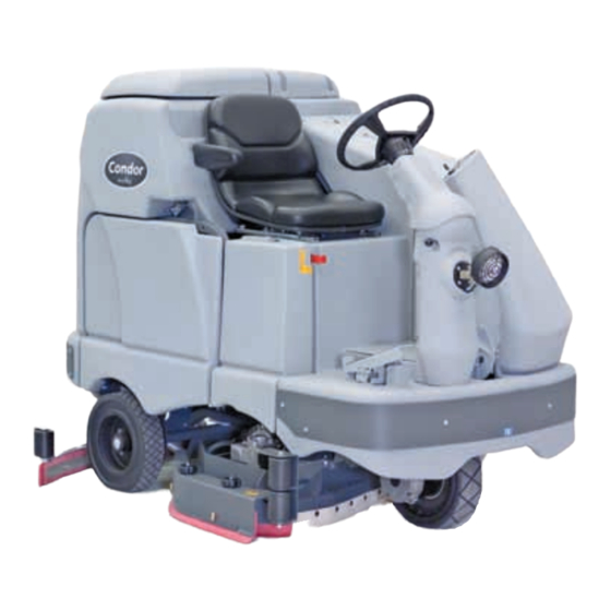
Condor
EcoFlex
™
Service Manual
Advance Models:
56381032 (X4030D-EcoFlex)
56381033 (X4030C-EcoFlex w/Side Broom)
56381034 (X4530D-EcoFlex)
56381035 (X4530C-EcoFlex w/Side Broom)
56381036 (X4830D-EcoFlex)
Nilfisk Models:
56413006 (BR1000 S EcoFlex w/o Side Broom)
56413010 (BR1300 S EcoFlex w/o Side Broom)
, BR 1100 S/SC EcoFlex
™
, BR 1300 S/SC EcoFlex
™
56381037 (X4830C-EcoFlex w/Side Broom)
56381043 (X4030C-EcoFlex w/o Side Broom)
56381044 (X4530C-EcoFlex w/o Side Broom)
56381045 (X4830C-EcoFlex w/o Side Broom)
56413007 (BR1000 S C EcoFlex w/Side Broom)
56413011 (BR1300 S C EcoFlex w/Side Broom)
™
English
7/11 Form No. 56043154
Advertisement
Table of Contents
Troubleshooting

Related Manuals for Nilfisk-Advance EcoFlex BR 1100 S


Summary of Contents for Nilfisk-Advance EcoFlex BR 1100 S
- Page 1 Condor EcoFlex , BR 1100 S/SC EcoFlex , BR 1300 S/SC EcoFlex ™ ™ ™ ™ Service Manual Advance Models: 56381032 (X4030D-EcoFlex) 56381037 (X4830C-EcoFlex w/Side Broom) 56381033 (X4030C-EcoFlex w/Side Broom) 56381043 (X4030C-EcoFlex w/o Side Broom) 56381034 (X4530D-EcoFlex) 56381044 (X4530C-EcoFlex w/o Side Broom) 56381035 (X4530C-EcoFlex w/Side Broom) 56381045 (X4830C-EcoFlex w/o Side Broom) 56381036 (X4830D-EcoFlex)
-
Page 2: Table Of Contents
Service Manual – Condor EcoFlex , BR 1100/1300 EcoFlex ™ ™ ™ Contents General Information Introduction Parts and Service Nameplate Transporting the Machine Towing Other Manuals Available for Your Machine Caution and Warning Symbols General Safety Instructions Emergency-stop Switch/Battery Disconnect Technical Specifications Dimensions General Machine Overview... - Page 3 Service Manual – Condor EcoFlex , BR 1100/1300 EcoFlex Contents ™ ™ ™ Scrub System, Disc Functional Description Component Locations Maintenance and Adjustments Troubleshooting Removal and Installation Specifications Special Tools Solution System Functional Description Component Locations Maintenance and Adjustments Troubleshooting Removal and Installation Specifications Squeegee System...
-
Page 4: General Information
Service Manual – Condor EcoFlex , BR 1100/1300 EcoFlex ™ ™ ™ General Information Introduction This manual will help you get the most from your Advance rider scrubber Read it thoroughly before servicing the machine Parts and Service Repairs should be performed by your Authorized Advance Service Center, which employs factory-trained service personnel and maintains an inventory of Advance original replacement parts and accessories Call the Advance dealer named below for repair parts or service Please specify the Model and Serial Number when discussing your machine... -
Page 5: Transporting The Machine
The manuals listed below can be found on Advance’s electronic supported databases They are: • Advance Dealer Customer Zone • EzParts service / parts CD-ROM • Nilfisk-Advance website: www.nilfisk-advance.com Manuals • Parts List - Form Number 56042467 • Instructions for Use - Form Number 56041986 (English, Spanish) -
Page 6: Caution And Warning Symbols
Service Manual – Condor EcoFlex , BR 1100/1300 EcoFlex General Information ™ ™ ™ Caution and Warning Symbols Advance uses the symbols below to signal potentially dangerous conditions Read this information carefully and take the necessary steps to protect personnel and property. Danger! Is used to warn of immediate hazards that will cause severe personal injury or death. - Page 7 Service Manual – Condor EcoFlex , BR 1100/1300 EcoFlex General Information ™ ™ ™ Caution! • This machine is not approved for use on public paths or roads. • This machine is not suitable for picking up hazardous dust. • Do not use scarifier discs and grinding stones. Advance will not be held responsible for any damage to floor surfaces caused by scarifiers or grinding stones.
-
Page 8: Emergency-Stop Switch/Battery Disconnect
Service Manual – Condor EcoFlex , BR 1100/1300 EcoFlex General Information ™ ™ ™ Emergency-stop Switch/Battery Disconnect is the red Emergency-stop/Battery Disconnect lever located to the right of the Operator’s seat In the event of an emergency, press the Emergency- in (toward the rear of stop/Battery Disconnect the machine) to disconnect the battery from the... -
Page 9: Technical Specifications
Service Manual – Condor EcoFlex , BR 1100/1300 EcoFlex General Information ™ ™ ™ Technical Specifications General Specifications Common to All Models Machine Length 73.5 in. [187 cm] Machine Height 58.5 in. [148.6 cm] Machine Height (w/overhead guard 84 in. [213 cm] Machine Body Width 40 in. - Page 10 Service Manual – Condor EcoFlex , BR 1100/1300 EcoFlex General Information ™ ™ ™ Specifications Common to Deck Size Model designations: 40” = Condor 4030 D/C; 45” = Condor 4530 D/C; 48” = Condor 4830 D/C 40” 45” 48” English 49 in.
-
Page 11: Dimensions
Service Manual – Condor EcoFlex , BR 1100/1300 EcoFlex General Information ™ ™ ™ Dimensions... -
Page 12: General Machine Overview
Service Manual – Condor EcoFlex , BR 1100/1300 EcoFlex General Information ™ ™ ™ General Machine Overview Major Machine Components Operator’s Seat Adjustment Lever Recovery Solution Tank Lid Tank Fill Cover Control Panel Operator’s Seat Battery Compartment (underneath Circuit recovery tank) Breakers Machine Battery... - Page 13 Service Manual – Condor EcoFlex , BR 1100/1300 EcoFlex General Information ™ ™ ™ Cover Recovery Assembly Tank Shutoff Valve Squeegee Vacuum Hose Recovery Tank Drain Hose Squeegee Height Adjust Knob Hopper (cylindrical models Squeegee Tilt only) Adjust Knob Solution Filter Squeegee Assembly...
-
Page 14: Control Panel
Service Manual – Condor EcoFlex , BR 1100/1300 EcoFlex General Information ™ ™ ™ Control Panel Switch and Button Functions The controls on your rider scrubber were designed with one-touch operation in mind For single-pass scrubbing, the user can simply depress one switch and all systems on the machine will be ready to go For most single-pass scrubbing operations, the operator should only need to use the middle switches on the control panel These are the red and the green... - Page 15 Service Manual – Condor EcoFlex , BR 1100/1300 EcoFlex General Information ™ ™ ™ ◦ If the direction is forward, the solution and detergent flow will also start automatically. ◦ If the direction is reverse, the solution and detergent flow will be stopped and the squeegee will be raised just enough to clear the floor surface.
- Page 16 Service Manual – Condor EcoFlex , BR 1100/1300 EcoFlex General Information ™ ™ ™ • – functions as follows: Vacuum/Wand Switch – If the machine is in the Auto Scrub mode, pressing this switch once will raise the squeegee. The vacuum motors will run for a short time delay, then shut off If you press the switch twice, the vacuum motors will shut off immediately This is used if you wish to double-scrub (scrub without recovering the solution)
- Page 17 Service Manual – Condor EcoFlex , BR 1100/1300 EcoFlex General Information ™ ™ ™ – In EcoFlex Mode 2, the default detergent ratio will be the programmed ratio Pressing the ™ EcoFlex ™ in Mode 2 will do the following: Button ◦...
- Page 18 Service Manual – Condor EcoFlex , BR 1100/1300 EcoFlex General Information ™ ™ ™ • Scrub On/Scrub Mode Select Indicator – The left side indicator will light when the normal scrub mode is selected – The right side indicator will light when the heavy scrub mode is selected –...
- Page 19 Service Manual – Condor EcoFlex , BR 1100/1300 EcoFlex General Information ™ ™ ™ • Side Broom On/Down Indicator – The indicator will be on when the side brooms are in the down working position, enabled and switched – The indicator will be off when the scrub system is switched off and the brooms are in the raised position •...
-
Page 20: General Maintenance
Service Manual – Condor EcoFlex , BR 1100/1300 EcoFlex General Information ™ ™ ™ Circuit Breakers The machine circuit breakers are located on the panel to the left of the Operator seat General Maintenance Maintenance After Use When finished scrubbing, press the Scrub Off Switch. This will automatically raise the scrub deck and squeegee, and switch off the solution, detergent and vacuum systems. -
Page 21: Maintenance Schedule
Service Manual – Condor EcoFlex , BR 1100/1300 EcoFlex General Information ™ ™ ™ d Inspect the for wear or damage Solution Tank Drain Hose Recovery Tank Drain Hose Vacuum Hose Replace the if kinked or damaged. Remove the brushes or pad holders Rinse the brushes or pads in warm water and hang up to dry Remove the squeegee, rinse it with warm water, then reinstall. - Page 22 Service Manual – Condor EcoFlex , BR 1100/1300 EcoFlex General Information ™ ™ ™ Machine Lubrication Once a month: • Steering Wheel Shaft Universal joint • Pump a small amount of grease into each grease • Steering Chain fitting on the machine as shown until grease •...
- Page 23 Solution Solenoid Valve Solution Tank, Delivery Hoses and Filter Clean Filter Screen Vacuum Motor Carbon Brushes Wear Limit 3/8" Vacuum Motor Cover Gasket and Filters Vacuum Float Ball and Cage Assembly Clean Float Copyright 2011 Nilfisk-Advance. Page 1 of 2 7/21/2011...
- Page 24 Note: For additional service information see Service Manual form number 56043154 and Instructions for Use form number 56041633. Work Completed By: Acknowledged By: Service Technician Signature Date Customer Signature Date Copyright 2011 Nilfisk-Advance. Page 2 of 2 7/21/2011...
-
Page 25: Chassis System
Service Manual – Condor EcoFlex , BR 1100/1300 EcoFlex ™ ™ ™ Chassis System Major Chassis Components Side Rear Panel Chassis Support Side Panel Assembly Pin Plate Weldment Conduit (2) Support Edge Trim Chassis Weldment... -
Page 26: Control System
Service Manual – Condor EcoFlex , BR 1100/1300 EcoFlex ™ ™ ™ Control System Functional Description Overview The control system consists of the A2 Control Board Assembly, the A3 Switch/Display Panel Assembly and associated sensors and circuitry A2 Control Board Assembly , sometimes referred to the A2 Control Board Assembly main controller, communicates with the... - Page 27 Service Manual – Condor EcoFlex , BR 1100/1300 EcoFlex Control System ™ ™ ™ A3 Switch/Display Panel Assembly The A3 Switch/Display Panel Assembly is the user interface that includes the various system switches and buttons, and the control panel display The A3 Switch/ Display Panel Assembly sends the operator inputs via a CAN BUS to the A2 Control Board Assembly Control System Wiring Diagram...
-
Page 28: Main Control Programming Options
Service Manual – Condor EcoFlex , BR 1100/1300 EcoFlex Control System ™ ™ ™ Main Control Programming Options Fault Recall Mode Whenever the A2 Control Board Assembly detects an electrical system error or fault, one or more error codes are displayed and stored by the A2 Control Board Assembly You can recall error codes (if any) from previous machine operation for troubleshooting purposes, To recall stored error codes: Turn the key switch off. - Page 29 Service Manual – Condor EcoFlex , BR 1100/1300 EcoFlex Control System ™ ™ ™ While holding both switches, turn the key switch on. Continue to hold both switches until both switch indicators turn on The display will show a wrench icon indicating fault detection mode Release both switches.
- Page 30 Service Manual – Condor EcoFlex , BR 1100/1300 EcoFlex Control System ™ ™ ™ Scrub Deck Down Time Adjustment Note that the factory default deck down time is two seconds. When scrub on switch is pressed, the control board will automatically lower the deck for two seconds. The time that the deck is lowered is adjustable from one second to three seconds in 0.1-second increments.
- Page 31 Service Manual – Condor EcoFlex , BR 1100/1300 EcoFlex Control System ™ ™ ™ Press the scrub off switch to save the new solution flow rate setting and move to the detergent concentration setting The display will now show the detergent icon with a next to it The –...
- Page 32 Service Manual – Condor EcoFlex , BR 1100/1300 EcoFlex Control System ™ ™ ™ 12 Turn the key switch off. The new settings will be saved until changed again. Extreme Scrub Setting Adjustment Note that the factory default settings for the extreme scrub setting are: Scrub pressure – three bars, Solution flow rate –...
- Page 33 Service Manual – Condor EcoFlex , BR 1100/1300 EcoFlex Control System ™ ™ ™ Scrub Speed Switch Lockout Note that the factory default setting for the scrub speed switch is FAST/SLOW - ENABLE The control system is programmed to limit the maximum travel speed while scrubbing to a value less than that allowed when driving and not scrubbing Pressing the scrub speed switch on the control panel will override this speed limiting feature and allow scrubbing at a the higher speed If you wish to prevent scrubbing at this faster speed, you can disable the scrub speed switch override feature To disable the scrub...
- Page 34 Service Manual – Condor EcoFlex , BR 1100/1300 EcoFlex Control System ™ ™ ™ Continue to hold the button for two seconds until the EcoFlex and scrub off indicators turn on ™ Release the EcoFlex button The display will now show the ™...
- Page 35 Service Manual – Condor EcoFlex , BR 1100/1300 EcoFlex Control System ™ ™ ™ Press the scrub off switch to save the setting and display the key switch icon. Turn the key switch off. The new setting will be saved until changed again. Solution Flow in Reverse Enable/Disable Note that the factory default setting for the solution flow in reverse option is ENABLE...
-
Page 36: Side Broom Height Adjustment
Service Manual – Condor EcoFlex , BR 1100/1300 EcoFlex Control System ™ ™ ™ Detergent and Solution Pump Purge The EcoFlex detergent system has two purge (flush) programs to ensure that the detergent delivery hoses ™ and related components are kept open and clean. A general operational description in how the system functions is found in the section To activate the maintenance purge functions: Solution System... -
Page 37: Service Test Mode
Service Manual – Condor EcoFlex , BR 1100/1300 EcoFlex Control System ™ ™ ™ Press and hold the side broom on/down and scrub off switches While holding the switches, turn the key switch on. Continue to hold the switches until the side broom on/down indicator, scrub off indicator and both scrub on indicators turn on Release the switches The indicators will stay on and the display will now show the side broom actuator down run time in seconds... - Page 38 Service Manual – Condor EcoFlex , BR 1100/1300 EcoFlex Control System ™ ™ ™ Continue to hold the scrub speed and traction control switches until the traction control indicator lights Release the scrub speed and traction control switches The scrub speed indicator will turn off and the display will show (speed controller - no fault) The display, switch and indicator NEUTRAL/SC-NO FAULT...
- Page 39 Service Manual – Condor EcoFlex , BR 1100/1300 EcoFlex Control System ™ ™ ™ • – This switch controls the squeegee lift actuator and vacuum Vacuum/Wand Switch motor(s) as follows: – Pressing the switch the first time will switch on vacuum motor(s) and switch on the actuator to lower the squeegee.
-
Page 40: Troubleshooting
Service Manual – Condor EcoFlex , BR 1100/1300 EcoFlex Control System ™ ™ ™ Troubleshooting Error Indicator and Error Code Display Any error codes detected by A2 Control Board Assembly will be Error displayed on the control panel Indicator display as they occur If more than one error exists, the display Two-digit will sequence through the error... - Page 41 Service Manual – Condor EcoFlex , BR 1100/1300 EcoFlex Control System ™ ™ ™ Display Error/Fault Description Correction Code Left brush motor contactor coil 1. Check for a coil wiring problem or a short circuit* overload (wire colors VIO and GRA/RED). 2.
- Page 42 Service Manual – Condor EcoFlex , BR 1100/1300 EcoFlex Control System ™ ™ ™ Display Error/Fault Description Correction Code Solution control pump overload 1. Check for short circuits* in the wiring and in the pump motor. • The normal current load is 0.8-1.8 2.
- Page 43 Service Manual – Condor EcoFlex , BR 1100/1300 EcoFlex Control System ™ ™ ™ Display Error/Fault Description Correction Code Left brush motor contactor coil short 1. Disconnect the coil wiring (wire colors VIO and to ground GRA/RED) and check to see if the code disappears. −...
- Page 44 Service Manual – Condor EcoFlex , BR 1100/1300 EcoFlex Control System ™ ™ ™ Display Error/Fault Description Correction Code Vacuum motor contactor coil open 1. Check for an open circuit in the coil and wiring (wire colors VIO and BLU). 2.
- Page 45 Service Manual – Condor EcoFlex , BR 1100/1300 EcoFlex Control System ™ ™ ™ Display Error/Fault Description Correction Code Side broom motor contactor coil 1. Disconnect the coil wiring (wire colors VIO and short to ground BRN/BLK) and check to see if the code disappears. −...
-
Page 46: Removal And Installation
Service Manual – Condor EcoFlex , BR 1100/1300 EcoFlex Control System ™ ™ ™ Removal and Installation Warning! Before removing or reinstalling any machine components, disconnect the battery pack by pushing in the emergency-stop switch/battery disconnect, and make sure the parking brake is engaged. A2 Control Board Assembly Remove the electrical panel cover assembly (located to the left of the... -
Page 47: Specifications
Service Manual – Condor EcoFlex , BR 1100/1300 EcoFlex Control System ™ ™ ™ Specifications Scrub Pressure and Current Load (Amps) Specifications Scrub Mode Scrub Deck Type Pressure Indicator Disc 40” Cyl. 40” Disc 45”/48” Cyl. 45”/48” Normal Scrub 1 bar (#1) 40 amps 35 amps 50 amps... -
Page 48: I/O Tables
Service Manual – Condor EcoFlex Control System ™ ™ I/O Tables A2 Control Board Assembly • Ladder Diagram: 56015372-G • Main PCB Assy: 56381049 • Main PCB Schematic: 56381059 • UI Panel Assy: 56381083 • UI PCB Schematic: 56381061 Nominal Wire ID/ Signal Reference... - Page 49 Service Manual – Condor EcoFlex Control System ™ ™ Nominal Wire ID/ Signal Reference Acceptable Designation Pin ID Description Value (when Comments Color Characteristics Range activated) UI Panel - Output J1-13 Voltage B- (ground) 0 - 1V Provides ground to User Interface panel Ground Input J1-14...
- Page 50 Service Manual – Condor EcoFlex Control System ™ ™ Nominal Wire ID/ Signal Reference Acceptable Designation Pin ID Description Value (when Comments Color Characteristics Range activated) Side Broom Output J2-7 GRN/ORN Voltage J2-8 see comment -36V while lowering, +36V while raising Actuator - Side Broom Output...
- Page 51 Service Manual – Condor EcoFlex Control System ™ ™ EcoFlex PCB Assembly • EcoFlex PCB Ass’y: 56316110-B ™ • EcoFlex PCB Schematic: 56314929-B ™ Nominal Signal Reference Acceptable Designation Pin ID Wire ID/Color Description Value (when Comments Characteristics Range activated) EcoFlex ™...
-
Page 52: Electrical System
Service Manual – Condor EcoFlex , BR 1100/1300 EcoFlex ™ ™ ™ Electrical System Functional Description Overview This section includes information on battery installation and maintenance, a description of the low-voltage cut-out function, and descriptions of the battery condition displays •... - Page 53 Service Manual – Condor EcoFlex , BR 1100/1300 EcoFlex Electrical System ™ ™ ™ Condor EcoFlex Ladder Wiring Diagram ™ BATTERY, 36 Vdc BATTERY, 36 Vdc FUSE, 250 A. FUSE, 250 A. RED/BLK BLU/BLK WHT/YEL BLK/WHT SPEED CONTROLLER SPEED CONTROLLER WHT/BLK ORN/RED BRN/RED...
-
Page 54: Low-Voltage Cut-Out Feature
Service Manual – Condor EcoFlex , BR 1100/1300 EcoFlex Electrical System ™ ™ ™ Low-voltage Cut-out Feature All models discussed in this manual are equipped with a low-voltage cutout feature to prevent over- discharging of the batteries. When a machine’s battery pack voltage falls below a specifically defined threshold (voltage settings), the scrub system automatically shuts down The drive motor will still operate in the low-voltage cut-out mode to allow the machine to be driven to a charging location The low-voltage cut-out level is adjustable The standard lead-acid battery (wet cell) setting is 1 72 volts per... -
Page 55: Battery Location
Service Manual – Condor EcoFlex , BR 1100/1300 EcoFlex Electrical System ™ ™ ™ Battery Location are located in the battery Batteries compartment behind the operator seat and underneath the recovery tank. Battery (6) Battery is mounted on the Disconnect Battery Disconnect right side of the operator seat Maintenance and Adjustments... - Page 56 Service Manual – Condor EcoFlex , BR 1100/1300 EcoFlex Electrical System ™ ™ ™ Checking the Battery Water Level Check the water level of the batteries at least once a week. After charging the batteries, remove the vent caps and check the water level in each battery cell. Use distilled or demineralized water in a battery filling dispenser (available at most auto parts stores) to fill each cell to the level indicator (or to approximately 3/8”...
-
Page 57: General Troubleshooting
Service Manual – Condor EcoFlex , BR 1100/1300 EcoFlex Electrical System ™ ™ ™ Caution! To avoid damage to floor surfaces, wipe water and acid from the top of the batteries after charging. Troubleshooting Battery Testing A battery problem is usually recognized by the machine operator as a decrease in the machine’s running time This condition is usually caused by one or more “dead cells”... -
Page 58: Removal And Installation
Service Manual – Condor EcoFlex , BR 1100/1300 EcoFlex Electrical System ™ ™ ™ Removal and Installation Warning! Before removing or reinstalling any machine components, make sure the key switch is off and the key is removed from the machine. To Install the Batteries Warning! •... -
Page 59: Specifications
Service Manual – Condor EcoFlex , BR 1100/1300 EcoFlex Electrical System ™ ™ ™ Carefully tighten the nut in each battery terminal until the terminal will not turn Do not overtighten the terminals or they will be very difficult to remove for future service. Coat the terminals with spray-on battery terminal coating (available at most auto parts stores) Put one of the black rubber boots over each of the terminals and connect the Battery Disconnect... -
Page 60: Options And Accessories
Service Manual – Condor EcoFlex , BR 1100/1300 EcoFlex ™ ™ ™ Options and Accessories Brush Selector Guide • ProLite: Light-duty polypropylene for general scrubbing • Prolene: Medium-duty scrubbing on concrete, terrazzo and vinyl floor tile. • Union Mix: Used for polishing floors. • Soft Nylon: For use on light dust coated floors where long life is required. - Page 61 Service Manual – Condor EcoFlex , BR 1100/1300 EcoFlex Options and Accessories ™ ™ ™ 4530D Pad Holders and Disc Brushes (three required) Description Short-trim pad holder with pad retainer, 16 inch [41 cm] Pad retainer/centering device only, snap lock ProLite disc brush, 16 inch [41 cm] Prolene disc brush, 16 inch [41 cm] Union Mix disc brush, 16 inch [41 cm]...
- Page 62 Service Manual – Condor EcoFlex , BR 1100/1300 EcoFlex Options and Accessories ™ ™ ™ 4830C Cylindrical Brushes and Side Brooms (two of each required) Description Soft nylon cylindrical brush, 48 inch [122 cm] Hard nylon cylindrical brush, 48 inch [122 cm] Prolene cylindrical brush, 48 inch [122 cm] MidLite Grit 180 cylindrical brush, 48 inch [122 cm] Dyna Grit 80 cylindrical brush, 48 inch [122 cm]...
- Page 63 Service Manual – Condor EcoFlex , BR 1100/1300 EcoFlex Options and Accessories ™ ™ ™ 4830C/D Squeegee Kits Description 55 inch [140 cm] squeegee blade kit, gum rubber, includes front and rear blade ® 55 inch [140 cm] squeegee blade kit, Linatex , includes front and rear blade 55 inch [140 cm] squeegee blade kit, polyurethane, includes front and rear blade Cylindrical deck side skirt, gum rubber, 1 each (2 required per deck)
- Page 64 Service Manual – Condor EcoFlex , BR 1100/1300 EcoFlex Options and Accessories ™ ™ ™ Batteries and Chargers Description 375 AH C6 monoblock battery 375 AH C6 monoblock battery with roll on roll off kit 450 AH C6 monoblock battery Shelf charger, single phase 230 VAC / 36 VDC, 38A, for 375 AH C6 battery Shelf charger, single phase SCR 240/480 VAC / 36 VDC, 96A max, for 450 AH C6 battery Shelf charger, three phase SCR 240/480 VAC / 36 VDC, 88A max, for 450 AH C6 battery...
-
Page 65: Recovery System
Service Manual – Condor EcoFlex , BR 1100/1300 EcoFlex ™ ™ ™ Recovery System Functional Description Overview The recovery system picks up the scrubbing solution from the squeegee Top Cover Float Cage tool and directs it to the Assembly Recovery Tank and Ball Recovery Tank Cover... - Page 66 Service Manual – Condor EcoFlex , BR 1100/1300 EcoFlex Recovery System ™ ™ ™ Float Cage and Ball A shutoff prevent the from being overfilled and stops any water from being Float Cage and Ball Recovery Tank sucked into the When the rises (to full-tank level) it will seat itself inside the Vacuum Motor...
-
Page 67: Component Locations
Service Manual – Condor EcoFlex , BR 1100/1300 EcoFlex Recovery System ™ ™ ™ Circuit Description get positive voltage from the when the load sides of contactors Vacuum Motors M5 Battery are closed Contactors close when the connects the contactor A2 Control Board Assembly coils to battery ground are connected directly to battery ground... - Page 68 Service Manual – Condor EcoFlex , BR 1100/1300 EcoFlex Recovery System ™ ™ ™ Top Cover Assembly is fastened to the top Top Cover Assembly of the recovery tank and includes the Vacuum Vacuum Filter Lid Filter Filter Screen Recovery Tank Filter Lid Vacuum Cover Plate Float Cage...
-
Page 69: Recovery Tank Lid
Service Manual – Condor EcoFlex , BR 1100/1300 EcoFlex Recovery System ™ ™ ™ Recovery Tank Lid is hinged Recovery Tank Lid and opens to allow access to the Recovery Tank Lid Recovery Tank Squeegee and Drain Hoses Squeegee Hose Drain are mounted on the rear of Hoses... -
Page 70: Maintenance
Service Manual – Condor EcoFlex , BR 1100/1300 EcoFlex Recovery System ™ ™ ™ Maintenance Warning! Before performing any machine maintenance or adjustments, make sure the key switch is off, the key is removed from the machine and the parking brake is engaged. To Inspect and Clean the Vacuum Filter and Inlet Screen Open the tethered Vacuum Filter Lid... -
Page 71: Troubleshooting
Service Manual – Condor EcoFlex , BR 1100/1300 EcoFlex Recovery System ™ ™ ™ Troubleshooting If water flows around the ends of the squeegee tool instead of being pulled into the tool, the vacuum system is not working correctly. This is usually due to either vacuum leaks, or restrictions in the squeegee tool, vacuum hoses or float cage. -
Page 72: Removal And Installation
Service Manual – Condor EcoFlex , BR 1100/1300 EcoFlex Recovery System ™ ™ ™ Removal and Installation Warning! Before removing or reinstalling any machine components, disconnect the battery pack by pushing in the emergency-stop switch/battery disconnect, and make sure the parking brake is engaged. Recovery Tank Drain the recovery tank. -
Page 73: Vacuum Motor
Service Manual – Condor EcoFlex , BR 1100/1300 EcoFlex Recovery System ™ ™ ™ Disconnect the from the back of Tank Tether the operator seat Caution: Maintain a good grip on the recovery tank and control the tank as you lower it. Do not allow the tank to fall to the floor on its own. - Page 74 Service Manual – Condor EcoFlex , BR 1100/1300 EcoFlex Recovery System ™ ™ ™ Remove the five from the Screws Top Cover , then lift the Assembly Top Cover Assembly straight up while guiding the float cage up through the opening in the recovery tank. Screw (5) Top Cover Assembly...
-
Page 75: Specifications
(Sealed) 68 in. H One Vacuum Motor (Open Hole Adapter 1”) 14 in. H Vacuum Lift (Sealed) 74 in. H Two Vacuum Motors (Open Hole Adapter 1”) 27 in. H Special Tools Vacuum water lift gauge, Nilfisk-Advance part number 56205281... -
Page 76: Scrub System, Cylindrical
Service Manual – Condor EcoFlex , BR 1100/1300 EcoFlex ™ ™ ™ Scrub System, Cylindrical Functional Description Overview The Condor EcoFlex cylindrical scrub deck models use two cylindrical brushes that counter-rotate to sweep ™ up light debris into a removable hopper, and scrub at the same time The two scrub brushes are powered on opposing ends by 1-1/2 HP permanent-magnet motors and drive belts The scrub deck actuator raises and lowers the scrub deck, and automatically adjusts the deck height while scrubbing to maintain the desired scrub pressure... - Page 77 Service Manual – Condor EcoFlex , BR 1100/1300 EcoFlex Scrub System, Cylindrical ™ ™ ™ Circuit Description The coil sides of contactors get positive voltage from the when the load side of contactor Battery is closed Contactor closes when the connects the coil to battery ground A2 Control Board Assembly...
-
Page 78: Component Locations
Service Manual – Condor EcoFlex , BR 1100/1300 EcoFlex Scrub System, Cylindrical ™ ™ ™ Component Locations The 1-1/2 HP permanent-magnet Scrub drive Motors Poly V Sheaves Drive Belts that drive the broom drive lug assemblies coupled to the brushes Scrub Deck Scrub Deck Actuator Assembly raises and lowers the scrub deck and... - Page 79 Service Manual – Condor EcoFlex , BR 1100/1300 EcoFlex Scrub System, Cylindrical ™ ™ ™ Weekly Maintenance • Clean the drain holes in the solution delivery trough on top of the scrub deck. • Clean any built-up dirt from the inside of the scrub brush housing •...
- Page 80 Service Manual – Condor EcoFlex , BR 1100/1300 EcoFlex Scrub System, Cylindrical ™ ™ ™ Rotate the 1” wide Idler Arm with an adjustable wrench so the is centered Idler Arm between the two holes drilled Idler into the motor mount plate This will provide a good preliminary tension setting Flat Head...
- Page 81 Service Manual – Condor EcoFlex , BR 1100/1300 EcoFlex Scrub System, Cylindrical ™ ™ ™ Service Note: You can also use the above actuator power cord adapter to help position the drive nut/spring housing assembly (in or out) for ease in actuator motor installations. Drive Nut Adjustment 1.
- Page 82 Service Manual – Condor EcoFlex , BR 1100/1300 EcoFlex Scrub System, Cylindrical ™ ™ ™ Hold onto the Spring Housing and press the rocker Assembly switch on the actuator power cord adapter to run the drive motor and retract the Spring toward the Housing Assembly...
- Page 83 Service Manual – Condor EcoFlex , BR 1100/1300 EcoFlex Scrub System, Cylindrical ™ ™ ™ Note: Use a 1/2” (13mm) socket to turn the adjuster. Each click of the adjuster will change the spring housing assembly travel 1/16 inch (1.6mm). 11 After each adjustment, hold the , run the actuator in and out and check both Spring Housing Assembly...
- Page 84 Service Manual – Condor EcoFlex , BR 1100/1300 EcoFlex Scrub System, Cylindrical ™ ™ ™ To reverse or replace the scrub system side skirt blade(s): Loosen the two side skirt Retainer (two per side) and remove Knobs from the Side Skirt Assemblies scrub deck.
-
Page 85: Troubleshooting
Service Manual – Condor EcoFlex , BR 1100/1300 EcoFlex Scrub System, Cylindrical ™ ™ ™ Troubleshooting Problem Cause Correction The scrub system Scrub deck sense R2 Scrub deck sensor resistor is unplugged or will not operate resistor fault (error code damaged. - Page 86 Service Manual – Condor EcoFlex , BR 1100/1300 EcoFlex Scrub System, Cylindrical ™ ™ ™ Problem Cause Correction The scrub system Right brush motor contactor 1. Check for an open circuit in the coil and wiring will not operate coil open (error code (wire colors VIO and YEL/BLU).
-
Page 87: Removal And Installation
Service Manual – Condor EcoFlex , BR 1100/1300 EcoFlex Scrub System, Cylindrical ™ ™ ™ Removal and Installation Warning! Before removing or reinstalling any machine components, make sure the key switch is off, key is removed from the machine and the parking brake is engaged. Scrub Brushes Make sure the scrub deck is in the raised position and the... - Page 88 Service Manual – Condor EcoFlex , BR 1100/1300 EcoFlex Scrub System, Cylindrical ™ ™ ™ Scrub Brush Deck Warning! Engage the parking brake and chock both rear wheels so the machine can’t roll. Loosen the four side skirt Scrub Deck Retainer Knobs Actuator (two per side) and...
- Page 89 Service Manual – Condor EcoFlex , BR 1100/1300 EcoFlex Scrub System, Cylindrical ™ ™ ™ 10 Remove the four , hex screws and bushings from the left and right front deck supports, then Hex Nuts swing the away from their mounting holes Pivot Support Arms Service Note: Removing both the left and right side brooms and both front chassis corner rollers will allow easier access to the mounting hardware on the four front scrub deck...
-
Page 90: Scrub Deck Lift Actuator
Service Manual – Condor EcoFlex , BR 1100/1300 EcoFlex Scrub System, Cylindrical ™ ™ ™ Scrub Deck Lift Actuator Note: All new replacement actuator motors are not shipped with the lift nut pre-adjusted for any specific machine model application. Note: The scrub deck must be removed to access the top mount bracket on the scrub deck lift motor. Remove the scrub deck by following the steps in the section Scrub Brush Deck... - Page 91 Service Manual – Condor EcoFlex , BR 1100/1300 EcoFlex Scrub System, Cylindrical ™ ™ ™ Scrub Brush Motor Note: It is not necessary to remove the complete scrub deck assembly from the machine to service an individual scrub brush motor. Remove the Side Skirt Assembly on the side of the deck...
-
Page 92: Specifications
Service Manual – Condor EcoFlex , BR 1100/1300 EcoFlex Scrub System, Cylindrical ™ ™ ™ 11 To install a Scrub Brush Motor: a Follow the above steps in reverse order with the exception that the drive belt tension must be reduced to allow the installation of the four motor mount Screws b Refer to the... -
Page 93: Scrub System, Disc
Service Manual – Condor EcoFlex , BR 1100/1300 EcoFlex ™ ™ ™ Scrub System, Disc Functional Description Overview The Condor EcoFlex disc models use rotary brushes powered by permanent-magnet motors and gearbox ™ assemblies. The 40” decks have two scrub brushes that are both powered by one 3 HP motor/gearbox assembly. - Page 94 Service Manual – Condor EcoFlex , BR 1100/1300 EcoFlex Scrub System, Disc ™ ™ ™ Circuit Description The coil sides of contactors get positive voltage from the when the load side of contactor K3 and K4 Battery is closed Contactor closes when the connects the coil to battery ground...
-
Page 95: Component Locations
Service Manual – Condor EcoFlex , BR 1100/1300 EcoFlex Scrub System, Disc ™ ™ ™ Component Locations On the 45” and 48” decks, three 1-1/2 HP drive the scrub brushes directly The Gearmotors 40” decks have a single 3 HP with two Gearmotor gearboxes (one on either end) that power the two... -
Page 96: Maintenance And Adjustments
Service Manual – Condor EcoFlex , BR 1100/1300 EcoFlex Scrub System, Disc ™ ™ ™ Maintenance and Adjustments Warning! Before performing any machine maintenance or adjustments, make sure the key switch is off, the key is removed from the machine and the parking brake is engaged. Lift Actuator Adjustment This section explains the steps for adjusting the actuator drive nut ( ) setting for the... - Page 97 Service Manual – Condor EcoFlex , BR 1100/1300 EcoFlex Scrub System, Disc ™ ™ ™ Drive Nut Adjustment 1. • If you’re installing a new scrub deck lift actuator motor, begin with step 2 below. • If you’re adjusting the on the existing scrub deck lift actuator, skip to step 5 on the following Drive Nut page...
- Page 98 Service Manual – Condor EcoFlex , BR 1100/1300 EcoFlex Scrub System, Disc ™ ™ ™ Hold onto the Spring Housing and press the rocker Assembly switch on the actuator power cord adapter to run the drive motor and retract the Spring toward the Housing Assembly...
- Page 99 Service Manual – Condor EcoFlex , BR 1100/1300 EcoFlex Scrub System, Disc ™ ™ ™ Note: Use a 1/2” (13mm) socket to turn the adjuster. Each click of the adjuster will change the spring housing assembly travel 1/16 inch (1.6mm). 11 After each adjustment, hold the , run the actuator in and out and check both Spring Housing Assembly...
- Page 100 Service Manual – Condor EcoFlex , BR 1100/1300 EcoFlex Scrub System, Disc ™ ™ ™ To reverse or replace the scrub system side skirt blade(s): Loosen the two side skirt Retainer (two per side) and remove Knobs from the Side Skirt Assemblies scrub deck.
-
Page 101: Troubleshooting
Service Manual – Condor EcoFlex , BR 1100/1300 EcoFlex Scrub System, Disc ™ ™ ™ Troubleshooting Problem Cause Correction The scrub system Scrub deck sense R2 Scrub deck sensor resistor is unplugged or will not operate resistor fault (error code damaged. - Page 102 Service Manual – Condor EcoFlex , BR 1100/1300 EcoFlex Scrub System, Disc ™ ™ ™ Problem Cause Correction The scrub system Left brush motor contactor 1. Check for an open circuit in the coil and wiring will not operate coil open (error code (wire colors VIO and GRA/RED) (continued) displayed)
- Page 103 Service Manual – Condor EcoFlex , BR 1100/1300 EcoFlex Scrub System, Disc ™ ™ ™ Problem Cause Correction The scrub deck Scrub deck actuator 1. Check for binding or a frozen brush lift linkage actuator doesn’t overload (error code and excessive weight on the brush deck. raise or lower the displayed) 2.
-
Page 104: Removal And Installation
Service Manual – Condor EcoFlex , BR 1100/1300 EcoFlex Scrub System, Disc ™ ™ ™ Removal and Installation Warning! Before removing or reinstalling any machine components, make sure the key switch is off and the key is removed from the machine. Scrub Brush Deck Warning! Engage the parking brake and chock both rear wheels so the machine can’t roll. - Page 105 Service Manual – Condor EcoFlex , BR 1100/1300 EcoFlex Scrub System, Disc ™ ™ ™ 10 Remove the four , hex screws and bushings from the left and right front deck supports, then Hex Nuts swing the away from their mounting holes Pivot Support Arms 11 Remove the previously-installed wood blocking from underneath the drive discs.
- Page 106 Service Manual – Condor EcoFlex , BR 1100/1300 EcoFlex Scrub System, Disc ™ ™ ™ Scrub Brush Motor and Gearbox To Remove and Install a Gearbox Assembly Remove the scrub brushes from the Brush Holder(s) Gearbox Assembly Use a 13mm socket wrench to remove Gearbox the three from each...
-
Page 107: Specifications
Service Manual – Condor EcoFlex , BR 1100/1300 EcoFlex Scrub System, Disc ™ ™ ™ Specifications Component Specifications Type – Permanent Magnet Voltage – 36 VDC 40” deck Power – 3 HP Speed – 2400 RPM Scrub Brush Motors Current – 75 Amps Voltage –... -
Page 108: Solution System
Service Manual – Condor EcoFlex , BR 1100/1300 EcoFlex ™ ™ ™ Solution System Functional Description Overview The solution system provides the solution and detergent to the scrub brushes The solution travels from the , through the to the The A2 Control Solution Tank Shutoff Valve In-line Solution Filter... -
Page 109: Solution Tank
Service Manual – Condor EcoFlex , BR 1100/1300 EcoFlex Solution System ™ ™ ™ Solution Tank holds 70 gallons (265 l) of solution. The solution fill cover opens to allow you to fill the Solution Tank . The solution empty switch is a float switch that closes and sends a signal to the A2 Control Solution Tank Board Assembly when the solution level in the falls to two to three inches from the bottom of... - Page 110 Service Manual – Condor EcoFlex , BR 1100/1300 EcoFlex Solution System ™ ™ ™ Detergent Tank and Pumps pump detergent from the to the tee fitting upstream of the solution Detergent Pumps Detergent Tank pump The get PWM voltage from the A2 Control Board to regulate the speed of the Detergent Pumps and the subsequent detergent flow.
- Page 111 Service Manual – Condor EcoFlex , BR 1100/1300 EcoFlex Solution System ™ ™ ™ and solution are connected to battery ground through the Solution Control Pump M12 Solenoid Valve L1 connects the and solution Control Board Assembly A2 Control Board Assembly Solution Control Pump M12 to ground to run the and switch on the...
-
Page 112: Component Locations
Service Manual – Condor EcoFlex , BR 1100/1300 EcoFlex Solution System ™ ™ ™ Component Locations Shutoff Valve is located underneath the Shutoff Valve solution tank on the left rear side of the machine. Shutoff Valve Drain Hose and Hose Cap are attached Drain Hose Drain Hose Cap... -
Page 113: Solution Solenoid Valve
Service Manual – Condor EcoFlex , BR 1100/1300 EcoFlex Solution System ™ ™ ™ Solution Control Pump pumps the solution Solution Control Pump through the solution solenoid valve to the nozzles adjacent to the scrub brushes The Solution Control gets PWM voltage from the A2 Control Pump Board to regulate the speed... -
Page 114: Accessory Pump
Service Manual – Condor EcoFlex , BR 1100/1300 EcoFlex Solution System ™ ™ ™ Accessory Pump is included in the Accessory Pump optional Spray Wand Kit The pump mounts on the underside of the chassis, Accessory Pump Detergent Tank and Pumps Detergent Tank Detergent Pumps are located behind the side access panel on... -
Page 115: Maintenance And Adjustments
Service Manual – Condor EcoFlex , BR 1100/1300 EcoFlex Solution System ™ ™ ™ Maintenance and Adjustments Warning! Before performing any machine maintenance or adjustments, make sure the key switch is off, the key is removed from the machine and the parking brake is engaged. To Disassemble and Clean the Solution Solenoid Valve Remove the solution solenoid valve from the machine (Refer to the Removal and Installation/Solution... - Page 116 Service Manual – Condor EcoFlex , BR 1100/1300 EcoFlex Solution System ™ ™ ™ To Clean the Solution Filter Close the solution shutoff valve to prevent solution from draining from the solution tank when servicing the filter with a partial or full solution tank. Note: Place a suitable container underneath the filter to catch any solution that may leak from the hoses.
- Page 117 Service Manual – Condor EcoFlex , BR 1100/1300 EcoFlex Solution System ™ ™ ™ To Purge the Detergent System Disconnect and remove the detergent tank. Install and connect a tank filled with clean water. Turn the key switch off. Press and hold both the detergent and solution switches While holding the switches, turn the key switch on.
-
Page 118: Troubleshooting
Service Manual – Condor EcoFlex , BR 1100/1300 EcoFlex Solution System ™ ™ ™ Troubleshooting Note: You can use the Service Test Mode to toggle the various system components on and off to check for function. Refer to the section for information on Control System/Service Mode how to enter and use the Service Test Mode. -
Page 119: Removal And Installation
Service Manual – Condor EcoFlex , BR 1100/1300 EcoFlex Solution System ™ ™ ™ Problem Cause Correction Inadequate or no The detergent system has Check that the detergent system has been selected detergent flow not been selected in the in the main control programming. main control programming. - Page 120 Service Manual – Condor EcoFlex , BR 1100/1300 EcoFlex Solution System ™ ™ ™ Solution Solenoid Valve Drain the solution tank or turn the solution shutoff valve to the off position to prevent solution loss. Disconnect the battery from the machine Note: Place a suitable container underneath the filter to catch any solution that may leak from the solenoid valve or hoses.
-
Page 121: Specifications
Service Manual – Condor EcoFlex , BR 1100/1300 EcoFlex Solution System ™ ™ ™ Specifications Solution Flow Rates Standard Flow Rates Override Flow Rates 1 bar 2 bars 3 bars 4 bars 5 bars 40” Disc .84 GPM 1.00 GPM 1.50 GPM 2.00 GPM 2.50 GPM... -
Page 122: Squeegee System
Service Manual – Condor EcoFlex , BR 1100/1300 EcoFlex ™ ™ ™ Squeegee System Functional Description Overview The squeegee system includes the squeegee tool and the squeegee lift actuator. The squeegee tool picks up the wastewater from the floor. The recovery system vacuum lifts the wastewater from the squeegee and directs it to the recovery tank. -
Page 123: Component Locations
Service Manual – Condor EcoFlex , BR 1100/1300 EcoFlex Squeegee System ™ ™ ™ Squeegee Lift Actuator Reverse Function The squeegee actuator operates in the automatic mode when scrubbing and will automatically lower to its normal operating position when the scrub system is enabled. To prevent squeegee blade damage and excessive wear, the will lift the squeegee tool from the floor when the machine is Squeegee Actuator M3... -
Page 124: Maintenance And Adjustments
Service Manual – Condor EcoFlex , BR 1100/1300 EcoFlex Squeegee System ™ ™ ™ Maintenance and Adjustments Warning! Before performing any machine maintenance or adjustments, make sure the key switch is off, the key is removed from the machine and the parking brake is engaged. To Reverse or Replace the Rear Squeegee Wiping Blade Raise the squeegee tool off the floor, then... -
Page 125: Squeegee Adjustment
Service Manual – Condor EcoFlex , BR 1100/1300 EcoFlex Squeegee System ™ ™ ™ Squeegee Adjustment There are two major squeegee tool adjustments–height and angle. The recommended procedure is to set the squeegee angle first, then adjust the squeegee blade height. To Adjust the Squeegee Angle Adjust the squeegee angle whenever a blade is reversed or... - Page 126 Service Manual – Condor EcoFlex , BR 1100/1300 EcoFlex Squeegee System ™ ™ ™ Lift Actuator Adjustment Using the Actuator Power Cord Adapter The adjacent drawing shows the special actuator power cord adapter (p/n 56407502) that is needed to connect the machine’s battery pack and actuator motor for setting the actuator drive nut limit settings To connect the actuator power cord adapter:...
-
Page 127: Troubleshooting
Service Manual – Condor EcoFlex , BR 1100/1300 EcoFlex Squeegee System ™ ™ ™ Measure the position of the on the shaft and compare the measurement with the Actuator Drive Nut position shown in the table below Part # Actuator Motor Actuator Drive Nut Actuator Drive Nut Models... -
Page 128: Removal And Installation
Service Manual – Condor EcoFlex , BR 1100/1300 EcoFlex Squeegee System ™ ™ ™ Removal and Installation Warning! Before removing or reinstalling any machine components, make sure the key switch is off, the key is removed from the machine and the parking brake is engaged. Squeegee Lift Actuator Remove the Squeegee... -
Page 129: Specifications
Service Manual – Condor EcoFlex , BR 1100/1300 EcoFlex Squeegee System ™ ™ ™ Specifications Component Specifications Type – permanent magnet, 36 VDC, 1/6 HP, reversible Motor-to-drive-screw ratio – 27.1:1 Performance Data Squeegee Actuator Motor No Load – Thrust 0 lbs., Speed 39 in/min, 1.4 Amps max. Full Load –... -
Page 130: Sweep System, Side Broom
Service Manual – Condor EcoFlex , BR 1100/1300 EcoFlex ™ ™ ™ Sweep System, Side Broom Functional Description Overview The optional side brooms are available on cylindrical deck machines only. The two 20-inch [50.8 cm] side brooms are mounted at the front corners of the machine and rotate in opposite directions to sweep dirt and debris into the main cylindrical brushes The main cylindrical brushes then sweep the dirt and debris into a removable hopper The side broom lift actuator raises and lowers the side brooms via a pivoting arm linkage assembly. -
Page 131: Component Locations
Service Manual – Condor EcoFlex , BR 1100/1300 EcoFlex Sweep System, Side Broom ™ ™ ™ Circuit Description The coil side of contactor gets positive voltage from the when the load side of contactor Battery closed Contactor closes when the connects the coil to battery ground A2 Control Board Assembly... -
Page 132: Maintenance And Adjustments
Service Manual – Condor EcoFlex , BR 1100/1300 EcoFlex Sweep System, Side Broom ™ ™ ™ Maintenance and Adjustments Warning! Before performing any machine maintenance or adjustments, make sure the key switch is off, the key is removed from the machine and the parking brake is engaged. Side Broom Height Adjustment The height of the side brooms is determined by the length of time the side broom actuator runs as it lowers the side brooms Note that:... - Page 133 Service Manual – Condor EcoFlex , BR 1100/1300 EcoFlex Sweep System, Side Broom ™ ™ ™ Lift Actuator Adjustment This section explains the steps for adjusting the actuator drive nut ( ) setting for the Spring Housing Assembly lift actuator motor Using the Actuator Power Cord Adapter The adjacent drawing shows the special actuator power cord adapter (p/n 56407502)
- Page 134 Service Manual – Condor EcoFlex , BR 1100/1300 EcoFlex Sweep System, Side Broom ™ ™ ™ Hold the then press the adapter cord rocker switch to run the drive motor to the Actuator Drive Nut position (wait until the motor stops) Measure the position of the on the shaft and compare the measurement with the Actuator Drive Nut...
-
Page 135: Troubleshooting
Service Manual – Condor EcoFlex , BR 1100/1300 EcoFlex Sweep System, Side Broom ™ ™ ™ Troubleshooting Problem Cause Correction Poor sweeping Brushes are worn or Check and replace the brushes as necessary. performance damaged Side The broom height is not set Check and reset the broom height. -
Page 136: Removal And Installation
Service Manual – Condor EcoFlex , BR 1100/1300 EcoFlex Sweep System, Side Broom ™ ™ ™ Removal and Installation Warning! Before removing or reinstalling any machine components, make sure the key switch is off, the key is removed from the machine and the parking brake is engaged. Side Broom Lift Actuator Note: New replacement lift actuator motors do not come with the lift drive nut pre-adjusted. - Page 137 Service Manual – Condor EcoFlex , BR 1100/1300 EcoFlex Sweep System, Side Broom ™ ™ ™ Side Broom Gearmotor Remove the Side Broom Retainer Pin Spring (2) Gearmotor then pull down on Assembly Side Broom remove it from the motor shaft Disconnect the motor Side Broom...
-
Page 138: Specifications
Service Manual – Condor EcoFlex , BR 1100/1300 EcoFlex Sweep System, Side Broom ™ ™ ™ Specifications Component Specifications Type – permanent magnet, 36 VDC Gearbox – 27:1 ratio Side Broom Gearnotor Power – 162 Watts Output – 105 in-lbs. @ 84 RPM Current –... -
Page 139: Wheel System, Non-Traction
Service Manual – Condor EcoFlex , BR 1100/1300 EcoFlex ™ ™ ™ Wheel System, Non-traction Functional Description Overview The non-traction wheel system supports the rear of the machine and includes the braking system. Component Locations (rear) Non-traction are attached to the Wheels brake and are... -
Page 140: Maintenance And Adjustments
Service Manual – Condor EcoFlex , BR 1100/1300 EcoFlex Wheel System, Non-traction ™ ™ ™ Maintenance and Adjustments Warning! Before performing any machine maintenance or adjustments, make sure the key switch is off and the key is removed from the machine. Chock both rear wheels so the machine can’t roll. - Page 141 Service Manual – Condor EcoFlex , BR 1100/1300 EcoFlex Wheel System, Non-traction ™ ™ ™ Brake Cable Adjustment Caution! Always test-ride the machine after making any adjustments to the brake system to confirm that the braking system is operating correctly. Make sure the parking brake lever is in the released (off) position.
-
Page 142: Troubleshooting
Service Manual – Condor EcoFlex , BR 1100/1300 EcoFlex Wheel System, Non-traction ™ ™ ™ Brake Caliper Pad Wear Adjustment Caution! Always test-ride the machine after making any adjustments to the brake system to confirm that the braking system is operating correctly. Note: The must not bottom out against the front slot on the caliper. -
Page 143: Removal And Installation
Service Manual – Condor EcoFlex , BR 1100/1300 EcoFlex Wheel System, Non-traction ™ ™ ™ Removal and Installation Warning! Before removing or reinstalling any machine components, make sure the key switch is off and the key is removed from the machine. Install wood blocking or chocks in front of and behind the front drive wheel to prevent the machine from rolling. - Page 144 Service Manual – Condor EcoFlex , BR 1100/1300 EcoFlex Wheel System, Non-traction ™ ™ ™ To reinstall the wheel and brake assembly: a Place the brake caliper onto the rotor and align the caliper slots with the chassis. b Slide the wheel and brake assembly onto the axle. Install the and washer to fasten the to the axle...
-
Page 145: Wheel System, Traction
Service Manual – Condor EcoFlex , BR 1100/1300 EcoFlex ™ ™ ™ Wheel System, Traction Functional Description Overview The traction wheel system includes the drive wheel assembly, Curtis A1 speed controller and associated circuitry, drive wheel steering assembly and the drive pedal assembly Drive Wheel Assembly The 1 75 HP Drive Motor Assembly... - Page 146 Service Manual – Condor EcoFlex , BR 1100/1300 EcoFlex Wheel System, Traction ™ ™ ™ Drive Wheel Steering Assembly The steering assembly transfers the steering wheel rotation through the steering shafts and universal joint to the at the bottom Steer Sprocket of the assembly The runs a chain connected to the front Steer Sprocket...
- Page 147 Service Manual – Condor EcoFlex , BR 1100/1300 EcoFlex Wheel System, Traction ™ ™ ™ Traction Wheel System Wiring Diagram Fuse, 250 A 36V Battery Traction Motor Rev. For. Pot. 5k Ohm Speed Controller Key Switch Seat Switch Circuit Breaker, 3 Amp Diode Battery Interlock Switch Motion...
-
Page 148: Component Locations
Service Manual – Condor EcoFlex , BR 1100/1300 EcoFlex Wheel System, Traction ™ ™ ™ Component Locations Drive Wheel Assembly Drive Wheel Assembly Seat is located underneath the Switch S2 Control Board Switch S1 front of the machine in Assembly line with the Drive Wheel Drive Wheel... -
Page 149: Maintenance And Adjustments
Service Manual – Condor EcoFlex , BR 1100/1300 EcoFlex Wheel System, Traction ™ ™ ™ Maintenance and Adjustments Warning! Before performing any machine maintenance or adjustments, make sure the key switch is off, the key is removed from the machine and the parking brake is engaged. Steering Chain Inspect the chain for looseness and binding Adjust the chain tension to 3/16”-1/4”... -
Page 150: Troubleshooting
Service Manual – Condor EcoFlex , BR 1100/1300 EcoFlex Wheel System, Traction ™ ™ ™ Troubleshooting General Troubleshooting Problem Cause Correction Wheel drive motor will not Batteries need charging (low battery Recharge the batteries. run in forward and reverse. voltage). Control Circuit Breaker ( ) is tripped. - Page 151 Service Manual – Condor EcoFlex , BR 1100/1300 EcoFlex Wheel System, Traction ™ ™ ™ Diagnostics Method B Method B uses the optional hand-held Curtis programmer model 1307, or the new model 1311 MP1101 With a programmer, diagnostics and troubleshooting is more direct than with the detergent system LED indicator alone The programmer presents complete diagnostic information in plain language with no codes to decipher Faults are displayed in the Diagnostic Menu, and the status of the controller inputs/outputs is displayed in the Test Menu...
- Page 152 Service Manual – Condor EcoFlex , BR 1100/1300 EcoFlex Wheel System, Traction ™ ™ ™ Status LED Fault Codes Status Light Explanation Possible Cause Code Display No power or defective controller Solid Controller or microprocessor fault Controller operational; no faults 0 (single LED flash every 5 seconds)
- Page 153 Service Manual – Condor EcoFlex , BR 1100/1300 EcoFlex Wheel System, Traction ™ ™ ™ Status Light Explanation Possible Cause Code Display 0000 0 Low battery voltage 1. Battery voltage <under-voltage cutback limit. 2. Corroded battery terminal. 3. Loose battery or controller terminal. 0000 00 Over-voltage 1.
-
Page 154: Removal And Installation
Service Manual – Condor EcoFlex , BR 1100/1300 EcoFlex Wheel System, Traction ™ ™ ™ Removal and Installation Warning! Before removing or reinstalling any machine components, make sure the key switch is off, the key is removed from the machine and the parking brake is engaged. Steering Chain Removal and Tensioning Turn the master key switch off and disconnect the battery pack emergency-stop/battery disconnect. - Page 155 Service Manual – Condor EcoFlex , BR 1100/1300 EcoFlex Wheel System, Traction ™ ™ ™ Front Drive Tire Note: It is not necessary to remove the complete wheel drive/spindle assembly to service the drive tire only. Warning! Turn the key switch off and disconnect the battery pack by pushing in the emergency-stop/battery disconnect red lever.
- Page 156 Service Manual – Condor EcoFlex , BR 1100/1300 EcoFlex Wheel System, Traction ™ ™ ™ Steering Spindle and Wheel Drive Assembly Warning! Turn the key switch off and disconnect the battery pack by pushing in the emergency-stop/battery disconnect red lever. Engage the machine parking brake and block both rear wheels so machine can’t roll.
- Page 157 Service Manual – Condor EcoFlex , BR 1100/1300 EcoFlex Wheel System, Traction ™ ™ ™ Warning! Never work under machine without safety stands or blocking to support the machine. Safely jack up or lift up the front of the machine 8-10 inches [20-25 cm] from the center bottom edge of the solution tank.
- Page 158 Service Manual – Condor EcoFlex , BR 1100/1300 EcoFlex Wheel System, Traction ™ ™ ™ Carbon Motor Brush Inspection and Replacement Warning! Turn the key switch off and disconnect the battery pack by pushing in the emergency-stop/battery disconnect red lever. Engage the machine parking brake and block both rear wheels so machine can’t roll.
- Page 159 Service Manual – Condor EcoFlex , BR 1100/1300 EcoFlex Wheel System, Traction ™ ™ ™ Potentiometer Removal and Testing Warning! Turn the key switch off and disconnect the battery pack by pushing in the emergency-stop/battery disconnect red lever. Engage the machine parking brake and block both rear wheels so machine can’t roll. Potentiometer Removal Remove the five holding the...
- Page 160 Service Manual – Condor EcoFlex , BR 1100/1300 EcoFlex Wheel System, Traction ™ ™ ™ Move one of the test leads to the middle connection and turn the stem in both directions The range of the readings should be approximately 1300-2500 Ohms or 2500-3700 Ohms, increasing and decreasing through its full range If you do not get these readings, replace the Potentiometer...
- Page 161 Service Manual – Condor EcoFlex , BR 1100/1300 EcoFlex Wheel System, Traction ™ ™ ™ Reconnect the three wires to the and the single GRN/YEL throttle . Make sure Potentiometer Ground Wire the wires are connected to the correct terminals as was noted when the drive pedal was removed Reinstall the drive pedal mount assembly onto the chassis, the reinstall and tighten the five Screws Test-drive the machine to check for correct speed and forward/reverse directional control.
- Page 162 Service Manual – Condor EcoFlex , BR 1100/1300 EcoFlex Wheel System, Traction ™ ™ ™ Drive Pedal Neutral Adjustment and Pedal Replacement If the drive pedal has been removed or replaced, the pedal neutral position will have to be set Follow the steps below to accomplish this Warning! Turn the key switch off and disconnect the battery pack by pushing in the emergency-stop/battery disconnect red lever.
- Page 163 Service Manual – Condor EcoFlex , BR 1100/1300 EcoFlex Wheel System, Traction ™ ™ ™ To Replace the Pedal or Spring Position the Torsion as shown Spring Ends This is with the and screw not Bushing installed Torsion Spring Place the Bushing inside the pedal Bushing...
- Page 164 Service Manual – Condor EcoFlex , BR 1100/1300 EcoFlex Wheel System, Traction ™ ™ ™ Warning! Put the vehicle up on blocks to get the drive wheel off the ground before beginning these tests. Turn the key switch off and make sure that the throttle is in neutral. Do not stand, or allow anyone else to stand, directly in front of or behind the vehicle during the tests.
-
Page 165: Specifications
Service Manual – Condor EcoFlex , BR 1100/1300 EcoFlex Wheel System, Traction ™ ™ ™ Specifications General Specifications Component Specifications Type – 36 VDC, separately-excited (field and armature) Power – 1.75 HP (continuous) Gear Ratio – 32:1, double reduction Drive Motor Assembly Speed –... -
Page 166: Special Tools
Service Manual – Condor EcoFlex , BR 1100/1300 EcoFlex Wheel System, Traction ™ ™ ™ A1 Speed Controller 16-Pin Connector Detail Detail of A1 16-pin Connector KEY SWITCH MODE 1 MODE 2 INPUT (KSI) SELECT SELECT INTERLOCK 16 15 14 13 12 11 10 9 8 7 6 5 4 3 2 1 AUXILIARY THROTTLE... -
Page 167: Appendix
Service Manual – Condor EcoFlex , BR 1100/1300 EcoFlex ™ ™ ™ Appendix Electrical Component Locations Item Description Speed Control Control Board Assembly Switch/Display Panel Assembly Circuit Breaker, 3 Amp (Control Circuit) Circuit Breaker, 15 Amp (Auxiliary Circuit) Circuit Breaker, 20 Amp (Side Brooms) Fuse, 250 Amp Backup Alarm (optional) Strobe Light (optional) -
Page 168: Ladder Diagram, Rev G
Service Manual – Condor EcoFlex , BR 1100/1300 EcoFlex Appendix ™ ™ ™ DWG. NO. Ladder Diagram, Rev. G BATTERY, 36 Vdc BATTERY, 36 Vdc Item Description FUSE, 250 A. FUSE, 250 A. Speed Control RED/BLK BLU/BLK WHT/YEL BLK/WHT Control Board Assembly SPEED CONTROLLER SPEED CONTROLLER Switch/Display Panel Assembly... - Page 169 Service Manual – Condor EcoFlex , BR 1100/1300 EcoFlex Appendix ™ ™ ™ Wiring Diagram, Rev. I DWG. NO. DISPLAY PANEL J3 J3 SWITCH, KEY SWITCH, KEY GROUND GROUND CONTROL BOARD CIRCUIT BREAKER, 3 AMP CIRCUIT BREAKER, 3 AMP CIRCUIT BREAKER, 15 AMP CIRCUIT BREAKER, 15 AMP CIRCUIT BREAKER, 20 AMP CIRCUIT BREAKER, 20 AMP...
-
Page 170: Detergent (Ecoflex™) System Plumbing Schematic
Service Manual – Condor EcoFlex , BR 1100/1300 EcoFlex Appendix ™ ™ ™ Detergent (EcoFlex™) System Plumbing Schematic Item Description Solution Tank Shutoff Valve Inline Solution Filter Solution Pump Detergent Tank Detergent Pump (2) Drain Hose Drain Plug Solution Solenoid Valve Reducer Tee Y Barb, Fitting Solution Manifold (Disc Models) - Page 171 Service Manual – Condor EcoFlex , BR 1100/1300 EcoFlex Appendix ™ ™ ™ Detergent (EcoFlex™) System Preparation and Purging Preparations for Use To Purge the Detergent System When Changing Detergents Fill the detergent cartridge with a maximum of 1 25 gallons [4 75 Liters] of detergent Disconnect and remove the detergent tank.
Need help?
Do you have a question about the EcoFlex BR 1100 S and is the answer not in the manual?
Questions and answers