Nilfisk-Advance SC3000 Service Manual
Hide thumbs
Also See for SC3000:
- Instructions for use manual (124 pages) ,
- Service manual (20 pages) ,
- Instructions for use manual (116 pages)
Table of Contents
Troubleshooting

Related Manuals for Nilfisk-Advance SC3000


Summary of Contents for Nilfisk-Advance SC3000
- Page 1 SC3000 Service Manual Nilfisk BR 652, 9087260020 - 9087261020 Nilfisk BR 752, 9087262020 - 9087263020 Nilfisk BR 752C, 9087264020 - 9087265020 Advance SC3000, 9087267020 English 2010-06 - Revised 2014-09 (6) Form No. 9098686000...
-
Page 2: Table Of Contents
Service Manual – SC3000 Table of contents Table of contents General Information Machine General Description Service Manual Purpose and Field of Application Other Reference Manuals Conventions Service and Spare Parts Serial Number Decal Safety Symbols General Instructions Machine Lifting Machine Transportation... - Page 3 Service Manual – SC3000 Table of contents Scrub System, Cylindrical Functional Description Wiring Diagram Component Location Maintenance and Adjustments Troubleshooting Removal and Installation Specifications Scrub System, Disc Functional Description Wiring Diagram Component Location Maintenance and Adjustments Troubleshooting Removal and Installation...
-
Page 4: Service Manual – Sc3000 Table Of Contents
Service Manual – SC3000 Table of contents... -
Page 5: General Information
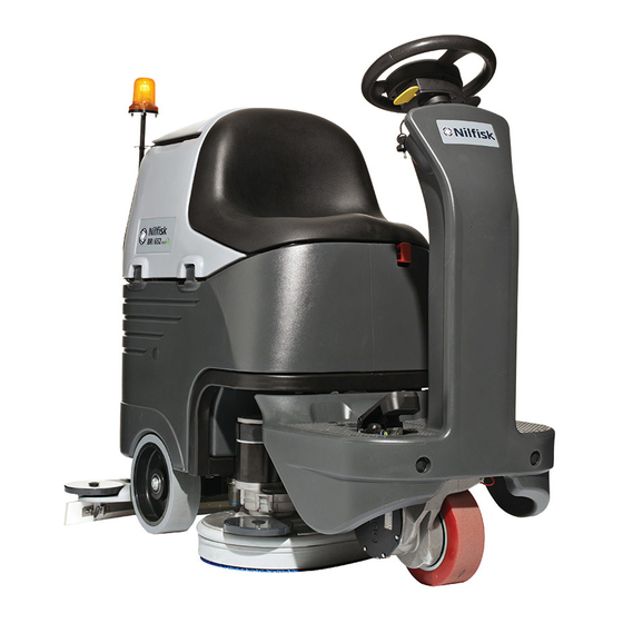
General Information Machine General Description The SC3000 is a “Ride-on” industrial machine designed to wash and dry floors in one pass. The machine is powered by on-board batteries, models can be equipped with EcoFlex™ system (optional). The machine fea- tures variable floor pressure disc or cylindrical brushes, controlled detergent solution dosing and a rear squee- gee with rubber blades that vacuums and dries the floor. -
Page 6: Conventions
Product code and year of production are marked on the same plate. This information is useful when requiring machine spare parts. Use the following table to write down the machine identification data. Model: Scrubber-Dryer SC3000 26D EcoFlex Serial No: ....Prod. Nr: 9087267020 Date code: ..IPX4... -
Page 7: Safety
Service Manual – SC3000 General Information Safety The following symbols indicate potentially dangerous situations. Always read this information carefully and take all necessary precautions to safeguard people and property. Symbols Danger! It indicates a dangerous situation with risk of death for the operator. - Page 8 Service Manual – SC3000 General Information Caution! Make sure to follow the safety precautions to avoid situations that may lead to serious injuries, damages to materials or equipments. − Carefully read all the instructions before performing any maintenance/repair procedure. − Before using the battery charger, ensure that frequency and voltage values, indicated on the machine serial number plate, match the electrical mains voltage.
- Page 9 Service Manual – SC3000 General Information − The machine working temperature must be between 0 °C and +40 °C. − The machine storage temperature must be between 0 °C and +40 °C. − The humidity must be between 30% and 95%.
-
Page 10: Machine Lifting
Service Manual – SC3000 General Information Machine Lifting Warning! Do not work under the lifted machine without supporting it with safety stands. Machine Transportation Warning! Before transporting the machine, make sure that: All covers are closed. The ignition key is removed. -
Page 11: Machine Nomenclature (Know Your Machine)
Service Manual – SC3000 General Information Machine Nomenclature (know your machine) Squeegee hook Seat Battery connector Emergency push-button Steering wheel with control panel Recovery tank cover Steering wheel height control lever Dumping recovery tank assembly Ignition key Battery charger Solution/clean... - Page 12 Service Manual – SC3000 General Information Machine Nomenclature (continued) Detergent tank Battery charger cable Electronic component compartment cover Vacuum grid with Lifted tank assembly automatic shut-off float and driver's seat Tank assembly stand Container with Vacuum system motor filter debris collection grid...
-
Page 13: Control Panel
Service Manual – SC3000 General Information Control Panel Battery lights Anti-skid control Reverse gear activation led indicator led indicator Washing detergent EcoFlex™ system flow control led indicator led indicator Hour counter and Detergent flow solution level display control push button... -
Page 14: Service And Diagnostic Equipment
• A copy of the User Manual and Spare Parts List of the machine to be serviced (provided with the machine or available at www.advance-us.com or other Nilfisk-Advance websites). The following equipment is also available at Nilfisk-Advance Centers: • Vacuum water lift gauge, P/N 56205281... -
Page 15: Technical Data
Service Manual – SC3000 General Information Technical Data General technical data Nilfisk BR 652 Description Nilfisk BR 752 Nilfisk BR 752C Advance SC3000 Cleaning width 26 in (660 mm) 30 in (710 mm) 30 in (710 mm) Squeegee width 35 in (890 mm) - Page 16 Service Manual – SC3000 General Information Technical Data (continued) Technical data for machines with disc deck Nilfisk BR 652 Description Nilfisk BR 752 Advance SC3000 Brush/pad diameter 13 in (330 mm) 355 mm Weight without batteries and with empty tanks 385.8 lb (175 kg)
-
Page 17: Dimensions
Service Manual – SC3000 General Information Dimensions Nilfisk BR 652 - Advance SC3000 1360 mm (53.5 in) 890 mm (35 in) P100367 Nilfisk BR 752 1360 mm (53.5 in) 890 mm (35 in) P100368... - Page 18 Service Manual – SC3000 General Information Dimensions (continued) Nilfisk BR 752C 1360 mm (53.5 in) 890 mm (35 in) P100369...
-
Page 19: Maintenance
Service Manual – SC3000 General Information Maintenance The lifespan of the machine and its maximum operating safety are ensured by correct and regular mainte- nance. Warning! Read carefully the instructions in the Safety chapter before performing any maintenance procedure. The following tables provides the scheduled maintenance. The intervals shown may vary according to particu- lar working conditions, which are to be defined by the person in charge of the maintenance. -
Page 20: Chassis System
Service Manual – SC3000 Chassis System Chassis System Frame (main parts) Steering assembly plate holder Tanks and driver's seat holder Rear wheels on fixed axle Front P100545... -
Page 21: Control System
Service Manual – SC3000 Control System Control System Functional Description The architecture of the electronic system controlling the electrical machine utilities consists of a main elec- tronic board (EB1), and a display electronic board (EB2) which is connected to the dashboard (EB3) - the main user interface. -
Page 22: Component Location
Service Manual – SC3000 Control System Component Location • Function electronic board (EB1) • Control panel electronic board (EB2) • Dashboard (EB3) Function electronic board (EB1) P100547 Control panel elec- tronic board (EB2) Dashboard (EB3) P100548... -
Page 23: Function Electronic Board Alarm Codes
Service Manual – SC3000 Control System Function Electronic Board Alarm Codes The function electronic board indicates a series of alarms in case of malfunction of one or more systems, and in case of abnormal conditions detected in the input signals. - Page 24 Service Manual – SC3000 Control System General alarms Alarm on the function electronic board - YELLOW LED + RED LED FLASHING Alarm No. of Code flashes Meaning Condition Effect Troubleshooting action on the on the display board Blown F2 fuse.
- Page 25 Service Manual – SC3000 Control System Function Electronic Board Alarm Codes (continued) P100549 P100551 Function electronic board alarms Alarm on the function electronic board - RED LED FLASHING Alarm No. of Code flashes Meaning Condition Effect Troubleshooting action on the...
- Page 26 Service Manual – SC3000 Control System Function Electronic Board Alarm Codes (continued) P100549 P100552 Drive system alarms Alarm on the function electronic board - YELLOW LED FLASHING Alarm No. of Code flashes Meaning Condition Troubleshooting action on the on the...
- Page 27 Service Manual – SC3000 Control System Function Electronic Board Alarm Codes (continued) Other alarm indications on the display Alarm Code on the Meaning Condition display “---” Water level signal missing or not as specified. Pressure switch module output higher than 4.0 Volt.
- Page 28 Service Manual – SC3000 Control System Black-box: Record of Alarms, Battery Management Parameters (see page 32 - 33), Partial Hour Counter (continued) Example 1: Last stored alarm: alarm G8 occurred when the machine working hours were 24h and 19m, next to last stored alarm: alarm F4 occurred when the machine working hours were 22h and 5m.
-
Page 29: Display Of Current Values Of Significant Variables, Hour Counters And Stored Alarms
Service Manual – SC3000 Control System Display of Current Values of Significant Variables, Hour Counters and Stored Alarms Turn the ignition switch to “0”. Open the electrical component compartment. Connect the ITALSEA programmer, NILFISK P/N 9097297000 to the function electronic board connector J9 (A). - Page 30 Service Manual – SC3000 Control System Display of Current Values of Significant Variables, Hour Counters and Stored Alarms (continued) Variable description Value meaning Software Release Software version loaded on the electronic board Supply Voltage Battery voltage (V) Ref. Voltage Drive pedal input voltage (V)
-
Page 31: Display And Change Of Parameters Which Can Be Set By The Technician
Service Manual – SC3000 Control System Display and Change of Parameters Which can be Set by the Technician The stored value of each parameter shown in the following table could be modified by the Service Operator from its Default value to another in the range defined from “Min. value” to “Max. value”. -
Page 32: Function Electronic Board Parameters
Service Manual – SC3000 Control System Function Electronic Board Parameters Parameters which can be set through programming port J9 Min. Default Max. Code Description Meaning values * values values It is the voltage supplied to the vacuum motor when Vacuum system partial supply... - Page 33 Service Manual – SC3000 Control System Parameters which can be set through programming port J9 Default Min. Max. Code Description Meaning values values * values It is the max istantaneous current that is possible to supply to the drive motorwheel.
-
Page 34: Removal And Installation
Service Manual – SC3000 Control System Removal and Installation Display Electronic Board and Dashboard Electronic Board Replacement Display Electronic Board Disassembly Drive the machine on a level floor. Turn the ignition key to “0” and disconnect the batteries. Remove the steering wheel height control lever and disconnect the wiring harness connection (A). - Page 35 Service Manual – SC3000 Control System Display Electronic Board and Dashboard Electronic Board Replacement (continued) Dashboard Electronic Board Disassembly Perform steps 1 to 5 of the Display Electronic Board Disassembly. Carefully lift and remove the dashboard electronic board (H) from the cover (C).
- Page 36 Service Manual – SC3000 Control System Function Electronic Board Lay-Out and Disassembly/Assembly Disassembly Drive the machine on a level floor. Turn the ignition key to “0” and disconnect the batteries. Lift the recovery tank assembly. Remove the 6 screws and remove the electronic component compartment cover.
- Page 37 Service Manual – SC3000 Control System Function Electronic Board Lay-Out and Disassembly/Assembly (continued) ◦ (F) Electrical component wiring harness connection (J1). ◦ (G) Foot board wiring harness connection (J3). ◦ (H) Frame wiring harness connection (J2). ◦ (I) Vacuum system wiring harness connection (VA+ and VA-).
-
Page 38: Specifications
Service Manual – SC3000 Control System Specifications Connectors on the function electronic board Power connections (male RADSOK terminals Ø6mm (AMPHENOL P/N N01 060 0001 1 or equivalent)) Electronic board Ref. Description V ref. I max. Connected to in/out Electronic board power supply +... - Page 39 Service Manual – SC3000 Control System Connectors (continued) J1: MOLEX MINIFIT type, 12-ways vertical Electronic board Description V ref. I max. Connected to in/out Brush electromagnetic switch power <1A supply + Brush electromagnetic switch power <1A supply - Brush fuse voltage drop reading + <1A...
- Page 40 Service Manual – SC3000 Control System Auxiliary power supply - <1A Connectors (continued) J3: MOLEX MINIFIT type, 10-ways vertical Electronic board Description V ref. I max. Connected to in/out Dashboard power supply + <1A EB2.1 Dashboard serial + in/out <1A EB2.2...
- Page 41 Service Manual – SC3000 Control System Connectors (continued) J5: MOLEX MINIFIT type, 2-ways vertical Electronic board Description V ref. I max. Connected to in/out Driving wheel brake power supply + Driving wheel brake power supply - J6: TYCO MODU1 type, 6-ways vertical...
- Page 42 Service Manual – SC3000 Control System Connectors (continued) J7: PRESSURE SWITCH connector, Berger type, 3+3-ways vertical ( ) Pressure switch power supply + <1A Press.A1 Pressure switch power supply - <1A Press.A2 Press.A3 Press.B1 Pressure switch signal + 0-5V <1A Press.B2...
-
Page 43: Electrical System
If the optional battery charger has not been installed, the relevant bridge must be used on connector C3. Battery charger The SC3000 may be equipped with an optional onboard battery charger. Depending on the market area and when the machine was manufactured, the charger may be an SPE charger or a Delta-Q charger. -
Page 44: Wiring Diagram (Spe Charger)
Service Manual – SC3000 Electrical System Wiring Diagram (SPE charger) 24 V battery box (BAT) Consent for battery charger Enabling from battery charger Battery fuse Battery charger data communication (F0) (**) Signal circuit Main electronic fuse (F3) board fuse (F2) -
Page 45: Component Location
Service Manual – SC3000 Electrical System Component Location • Batteries (BAT) • Battery connections • SPE charger (CH) • (for Nilfisk scrubbers version only) Battery fuse (F0) • Battery connector (C1) • Delta-Q charger (CH) SPE charger (CH) Batteries (BAT) - Page 46 Service Manual – SC3000 Electrical System Component Location (continues) • Electrical panel • Function electronic board (EB1) Function electronic Electrical panel board (EB1) P100556...
-
Page 47: Maintenance And Adjustments
Service Manual – SC3000 Electrical System Maintenance and Adjustments Charge condition display (SPE charger only) Set the electronic board of the machine and the on board battery charger according to the type of batteries installed (WET or GEL/AGM) as shown below: Turn the ignition key to “I”... - Page 48 Service Manual – SC3000 Electrical System Delta-Q IC 650 Charge Profile Selection Set the DELTA-Q on-board charger according to the type of batteries installed as shown below: Disconnect AC input (A) from the charger, or from the wall outlet. Wait 30 seconds for the input relay to open.
- Page 49 Service Manual – SC3000 Electrical System Delta-Q IC 650 Charge Profile Selection (continues) Available charging profiles are as follows: BATTERY CHARGER PROFILE SELECTION CHART FOR USE WITH DELTA-Q ON-BOARD CHARGER (N-A P/N 56383856) Battery Battery 20 Hour N-A P/N Voltage...
- Page 50 Service Manual – SC3000 Electrical System Charge condition display TRANSITION THRESHOLD (VOLT) INDICATION CONSEQUENCE GREEN LED: fixed - YELLOW LED: fixed 22 V 22.2 V YELLOW LED: fixed - RED LED: flashing 20.4 V 21.6 V Brushes OFF Safety threshold 19.4 V...
-
Page 51: Troubleshooting
Service Manual – SC3000 Electrical System Troubleshooting See the other chapters related to the use of the electrical system. Trouble Possible Causes Remedy The machine is not working The batteries (BAT) are discharged or its connections are Charge the batteries or clean the... -
Page 52: General Wiring Diagram
Service Manual – SC3000 Electrical System General Wiring Diagram Battery connector (C1+) Electromagnetic brake (BRK) Vacuum Drive Brush deck system system connector (C4+) motor (M2) motor (M3) Squeegee actuator motor (M6) Brush motor (M1.1,2) 24 V battery Flashing box (BAT) -
Page 53: Specifications
Service Manual – SC3000 Electrical System Specifications Battery compartment size (length x width x height) 14.9 x 21.2 x 11.8 in (380 x 540 x 300 mm) 4 6 V batteries, 180 Ah C5 (WET) Battery type 4 6 V batteries, 180 Ah C5 (GEL/AGM) Standard batteries autonomy (capacity) 2.5 - 3.5 hours... -
Page 54: Recovery System
Service Manual – SC3000 Recovery System Recovery System Functional Description The water recovery system removes the dirty water from the floor and pipes it to a recovery tank. When the machine is running, the dirty water on the floor is collected by the squeegee blades and collected through the slots in the same, piped through the vacuum hose and into the tank by the airflow created by Vacuum system motor (M2). -
Page 55: Component Location
Service Manual – SC3000 Recovery System Component Location • Recovery tank • Squeegee vacuum hose • Recovery tank cover • Recovery water drain hose • Gasket cover • Vacuum system wiring harness connection • Container with debris collection grid • Function electronic board (EB1) •... -
Page 56: Maintenance And Adjustments
Service Manual – SC3000 Recovery System Maintenance and Adjustments Recovery Tank Cleaning Drive the machine to the appointed disposal area. Turn the ignition key to “0”. Open the recovery tank cover. Clean and wash the cover and the recovery tank with clean water. -
Page 57: Troubleshooting
Service Manual – SC3000 Recovery System Troubleshooting Trouble Possible Causes Remedy The vacuum system motor does not turn The wiring harness between function electronic board Repair (EB1) and vacuum system motor (M2) is damaged The vacuum system motor carbon brushes are worn... -
Page 58: Removal And Installation
Service Manual – SC3000 Recovery System Removal and Installation Vacuum system motor electrical input check Warning! This procedure must be performed by qualified personnel only. Install an Amp clamp (A) on one cable (B) of the batteries. Turn the ignition key to “I”. Turn on the vacuum system by pressing the vacuum system push button and check that the motor electrical input is 16 - 19 A at 24 V. - Page 59 Service Manual – SC3000 Recovery System Vacuum System Motor Carbon Brush Check/Replacement Remove the vacuum system motor (see the procedure in the following paragraph). At the workbench, remove the screws and the cover (A) from the vacuum system motor (B).
- Page 60 Service Manual – SC3000 Recovery System Vacuum System Motor Disassembly/Assembly Disassembly If there is recovery water in the tank, drain it. Turn the ignition key to “0” and disconnect the batteries. Lift the recovery tank assembly. Remove the screws (A) and recover the washers.
-
Page 61: Specifications
Service Manual – SC3000 Recovery System Specifications Advance SC3000 Description Nilfisk BR 652 Nilfisk BR 752 Nilfisk BR 752C Recovery tank capacity 21 US gal (80 L) 0.56 hp (420 W) 20.8A VDC 24V Vacuum system motor technical data 14900 rpm 0.0146 MPa (1,448 mmH... -
Page 62: Scrub System, Cylindrical
Service Manual – SC3000 Scrub System, Cylindrical Scrub System, Cylindrical Functional Description The cylindrical brush system can be started by the operator. The cylindrical brushes turn in opposite directions towards the centre of the deck. The rotating brush system cleans the surface of the floor. The deck, where brushes suitable for cleaning the particular type of floor are installed, is the main part of the brush system. -
Page 63: Wiring Diagram
Service Manual – SC3000 Scrub System, Cylindrical Wiring Diagram Power supply (B+) Function electronic Brush motors board (EB1) (M1.1 - M1.2) Brush motor J1.2 electromagnetic switch Negative ref. J1.1 (ES1) Positive ref. Shunt + Brush deck fuse (F1) Shunt -... -
Page 64: Component Location
Service Manual – SC3000 Scrub System, Cylindrical Component Location • Cylindrical brush deck • Roller belt tensioner • Debris container • Driving belt • Side skirts • Brush pulley • Crankcase belt protection • Support brush • Front deck protection •... - Page 65 Service Manual – SC3000 Scrub System, Cylindrical Component Location (continued) • Brush deck lifting/lowering actuator • Brush deck fuse (F1) • Brush motor electromagnetic switch (ES1) • Actuator system wiring harness connection • Brush motor (M1.1 - M1.2) • Function electronic board (EB1)
-
Page 66: Maintenance And Adjustments
Service Manual – SC3000 Scrub System, Cylindrical Maintenance and Adjustments Cylindrical brush installation/removal Insert the ignition key and turn it to “I”. Warning! Before pressing the scrub On/Off push button , always check that, between the deck and the machine there is no foreign material which may prevent the deck from lifting. -
Page 67: Side Skirt Check And Replacement
Service Manual – SC3000 Scrub System, Cylindrical Side skirt check and replacement Check Assembly and height adjustment Drive the machine on a level floor. Assemble the blades (G) and skirt assembly (B) Turn the ignition key to “0”. in the reverse order of disassembly. -
Page 68: Troubleshooting
Service Manual – SC3000 Scrub System, Cylindrical Troubleshooting Open circuit • The Brush deck fuse (F1) determines an open in the supply circuit of the brush deck motors. This system allows to prevents the wiring from being damaged under overload conditions. -
Page 69: Removal And Installation
Service Manual – SC3000 Scrub System, Cylindrical Removal and Installation Removing and Installing the Brush Deck washer. Disassembly Drive the machine on a level floor or on a Turn the ignition key to “I”, lift the deck holder hoisting system to facilitate the disassembly (E) by pressing the scrub On/Off push button procedures. - Page 70 Service Manual – SC3000 Scrub System, Cylindrical Brush motor electrical input check Warning! This procedure must be performed by qualified personnel only. Drive the machine on a level floor. Remove the brushes. Place two wooden shims (A) under the side areas of the cylindrical brush deck (C) as shown in the figure.
- Page 71 Service Manual – SC3000 Scrub System, Cylindrical Brush Motor Electrical Input Check (continued) Reset 17. Connect the driving wheel connector. 18. Remove the jumper wire and enable the driver's seat microswitch. 19. Remove the wooden shims and install the brushes.
- Page 72 Service Manual – SC3000 Scrub System, Cylindrical Brush Motor Carbon Brush Check/Replacement Check Remove the brush motor. At the workbench, remove dust and debris from the motor, especially in the area of the protection clamp (A). Remove the protection clamp (A).
- Page 73 Service Manual – SC3000 Scrub System, Cylindrical Brush Motor Disassembly/Assembly Disassembly Remove the cylindrical brush deck (see the procedure in “Cylindrical Brush Deck Disassembly/ Assembly” paragraph). On the machine side where the brush motor has to be removed, unscrew the knobs and remove the side skirt assembly.
- Page 74 Service Manual – SC3000 Scrub System, Cylindrical Brush Motor Disassembly/Assembly (continued) Remove the guard (C). Loosen the nut (D) and move the pulley (E) to loosen the belt (F). Remove the belt (F). Remove the screws (G). Remove the motor (H).
- Page 75 Service Manual – SC3000 Scrub System, Cylindrical Check/replacement/adjustment of driving belts between motors and cylindrical brushes Check Drive the machine on a level floor. Lower the brush deck by pressing the scrub On/Off push button Turn the ignition key to “0” and disconnect the batteries.
- Page 76 Service Manual – SC3000 Scrub System, Cylindrical Check/replacement/adjustment of driving belts between motors and cylindrical brushes (continued) Replacement If the belt (C) is to be replaced, remove the guard (D), loosen the nut (E) and move the pulley (F) to loosen the belt.
- Page 77 Service Manual – SC3000 Scrub System, Cylindrical Brush Deck Lifting/Lowering Actuator Disassembly/Assembly Disassembly Lower the brush deck. Remove the cylindrical brush deck (see the procedure in “Cylindrical Brush Deck Disassembly/ Assembly” paragraph). Turn the ignition key to “0” and disconnect the batteries.
-
Page 78: Specifications
Service Manual – SC3000 Scrub System, Cylindrical Specifications Description Nilfisk BR 752C Cleaning width 28 in (710 mm) Cylindrical brush size (diameter x length) 5.7 x 27.2 in (145 x 690 mm) Deck right/left offset 3.5 / 3.5 in (90 / 90 mm) Cylindrical brush deck distance from the floor (when lifted) 0.8 in (22 mm) -
Page 79: Scrub System, Disc
Service Manual – SC3000 Scrub System, Disc Scrub System, Disc Functional Description The disc brush system can be started by the operator. The disc brushes turn in opposite directions towards the centre of the header. The rotating brush system cleans the surface of the floor. The deck, where brushes suitable for cleaning the particular type of floor are installed, is the main part of the brush system. -
Page 80: Wiring Diagram
Service Manual – SC3000 Scrub System, Disc Wiring Diagram Power supply (B+) Function electronic Brush motors board (EB1) (M1.1 - M1.2) Brush motor J1.2 electromagnetic switch Negative ref. J1.1 (ES1) Positive ref. Shunt + Brush deck fuse (F1) Shunt -... -
Page 81: Component Location
Service Manual – SC3000 Scrub System, Disc Component Location • Disc brush deck • Gas spring for extra pressure • Brush gearmotor (M1, M2) • Brush electromagnetic switch (ES1) • Drive hub • “Magic deck” system • Brush deck lifting/lowering actuator (M5) - Page 82 Service Manual – SC3000 Scrub System, Disc Component Location (continued) • Brush deck fuse (F1) • Actuator system wiring harness connection • Function electronic board (EB1) Function electronic board (EB1) Actuator system wiring harness con- nection Brush deck fuse (F1)
-
Page 83: Maintenance And Adjustments
Service Manual – SC3000 Scrub System, Disc Maintenance and Adjustments Brush/pad-holder installation/removal Insert the ignition key and turn it to “I”. Warning! Before pressing the scrub On/Off push button , always check that, between the deck and the machine there is no foreign material which may prevent the deck from lifting. -
Page 84: Troubleshooting
Service Manual – SC3000 Scrub System, Disc Troubleshooting Open circuit • The fuse (F1) determines an open in the supply circuit of the brush deck motors. This system allows to prevent the circuits from being damaged under overload conditions. • The open in the fuse can be caused by the following: ◦... -
Page 85: Removal And Installation
Service Manual – SC3000 Scrub System, Disc Removal and Installation Removing and Installing the Brush Deck Disconnect the solution hose union (B). Disassembly Drive the machine on a level floor or on a Remove the screw (C) and recover the nut. - Page 86 Service Manual – SC3000 Scrub System, Disc Brush motor electrical input check Warning! This procedure must be performed by qualified personnel only. Drive the machine on a level floor. Remove the brushes. Place two wooden shims (A) under the side areas of the deck (C) as shown in the figure. Wooden shim thickness must be 25 mm.
- Page 87 Service Manual – SC3000 Scrub System, Disc Brush Motor Electrical Input Check (continued) Reset 17. Connect the driving wheel connector. 18. Remove the jumper wire and enable the driver's seat microswitch. 19. Remove the wooden shims and install the brushes.
- Page 88 Service Manual – SC3000 Scrub System, Disc Brush Motor Carbon Brush Check/Replacement Check Remove the brush/pad-holder deck. Remove dust and dirt from the motor carbon brush support area (A). Disengage the fasteners (B) and (C), then remove the four carbon brush supports (A). If necessary, disconnect the electrical connections (D).
- Page 89 Service Manual – SC3000 Scrub System, Disc Brush Motor Disassembly/Assembly Disassembly Assembly Remove the brush/pad-holder deck. Assemble the components in the reverse order of At the workbench, remove the screw (A) from disassembly. the reduction unit which has to be disassembled.
- Page 90 Service Manual – SC3000 Scrub System, Disc Brush Deck Lifting/Lowering Actuator Disassembly/Assembly Disassembly Lower the brush deck. Remove the deck. Turn the ignition key to “0” and disconnect the batteries. Disconnect the actuator connector (see the function electronic board). Remove the screw (A) and recover nuts, bushings and washers.
- Page 91 Service Manual – SC3000 Scrub System, Disc Brush Deck Adjuster Spring Disassembly/Assembly Disassembly Drive the machine on a level floor. Remove the brush deck. Turn the ignition key to “0” and disconnect the batteries. Remove the front fairing (see the procedure in “Front Fairing Disassembly/Assembly” paragraph, Steering System section).
- Page 92 Service Manual – SC3000 Scrub System, Disc Brush Deck Drive Guide Disassembly/Assembly Disassembly Drive the machine on a level floor. Remove the brush/pad-holder deck and leave the deck holder assembly lifted. Turn the ignition key to “0” and disconnect the batteries.
-
Page 93: Specifications
Service Manual – SC3000 Scrub System, Disc Specifications Nilfisk BR 652 Description Nilfisk BR 752 Advance SC3000 Cleaning width 26 in (660 mm) 28 in (710 mm) Brush/pad diameter 13 in (330 mm) 14 in (355 mm) 0 ÷ 3.9 in / 1 ÷ 0 in 0.6 ÷... -
Page 94: Solution System
Service Manual – SC3000 Solution System Solution System Functional Description The solution system supplies water and detergent to the brushes when cleaning the floor. The solution tank is also the main machine body. There is a manual valve on the right side of the tank to close the water sup- ply whenever maintenance must be performed on the machine. -
Page 95: Component Location
Service Manual – SC3000 Solution System Component Location • Solution/clean water tank • EcoFlex™ detergent tank • Filling cap • EcoFlex™ detergent pump (M4) • Solution/clean water valve • One-way valve • Solution filter • Solution/clean water drain valve • Solenoid valve (EV1) •... -
Page 96: Maintenance And Adjustments
Service Manual – SC3000 Solution System Maintenance and Adjustments Solution/clean water tank emptying Drive the machine to the appointed disposal area. Turn the ignition key to “0”. Remove the adapter from its housing inside the battery compartment. Install the adapter (A) on the squeegee vacuum hose (B), then fasten it to the drain valve (C). -
Page 97: Solution Filter Cleaning
Service Manual – SC3000 Solution System Solution filter cleaning Drive the machine on a level floor. Turn the ignition key to “0”. Close the solution valve (A) under the machine, behind the right rear wheel. The valve (A) is closed when it is in the position (B) and it is open when it is in the position (C). - Page 98 Service Manual – SC3000 Solution System EcoFlex™ System Draining Clean the detergent tank according to the procedure shown in the previous paragraph. To remove the detergent remained in the hoses and in the pump, perform the following procedure. Turn on the machine by turning the ignition key to “I”.
- Page 99 Service Manual – SC3000 Solution System EcoFlex™ system disabling procedure In order to permanently disable the EcoFlex™ system, proceed as follows: Turn off the machine by turning the ignition key (A) to “0”. Lift the lever (B), then turn the ignition key (A) to “I”.
-
Page 100: Troubleshooting
Service Manual – SC3000 Solution System Troubleshooting Trouble Possible Causes Remedy Small amount of solution or no solution The tank filter (optional) is clogged/dirty Clean the filter reaches the brush The solution filter is clogged/dirty Clean the filter The solution valve is closed/semi-closed... - Page 101 Service Manual – SC3000 Solution System Troubleshooting (continued) Trouble Possible Causes Remedy Small amount of EcoFlex ™ detergent or The detergent flow percentage is too low Check/change the percentage as no detergent reaches the brush shown in the User Manual...
-
Page 102: Removal And Installation
Service Manual – SC3000 Solution System Removal and Installation Solution System Solenoid Valve/Filter Disassembly/Assembly Disassembly Assembly Place the machine on a hoisting system (if Assemble the components in the reverse order of available), then lift it. Otherwise, drive the disassembly, and note the following: machine on a level floor. - Page 103 Service Manual – SC3000 Solution System Detergent Pump And One-Way Valve Disassembly/Assembly Disassembly Assembly Place the machine on a hoisting system (if 10. Assemble the components in the reverse order of available), then lift it. Otherwise, drive the disassembly, and note the following: machine on a level floor.
-
Page 104: Specifications
Service Manual – SC3000 Solution System Specifications Nilfisk BR 652 Description Nilfisk BR 752 Nilfisk BR 752C Advance SC3000 Solution/clean water tank capacity 21 US gal (80 L) Solution flow 0.26 to 0.8 US gal/min. (1 to 3 L/min.) Minimum/maximum solution flow (with and without EcoFlex™... -
Page 105: Squeegee System
Service Manual – SC3000 Squeegee System Squeegee System Functional Description The squeegee system cleans the liquid off the floor, which is then collected by the recovery system. The squeegee is mounted on castors and the weight of the system presses it down on the floor. -
Page 106: Component Location
Service Manual – SC3000 Squeegee System Component Location • Squeegee • Squeegee blades • Squeegee holder • Mounting handwheels • Squeegee adjustment • Actuator (M6) • Squeegee lifting cable Actuator (M6) Squeegee lifting cable Squeegee adjust- ment Squeegee holder Mounting hand-... -
Page 107: Maintenance And Adjustments
Service Manual – SC3000 Squeegee System Maintenance and Adjustments Squeegee cleaning Note: The squeegee must be clean and its blades must be in good conditions in order to get a good drying. Warning! It is advisable to wear protective gloves when cleaning the squeegee because there may be sharp debris. -
Page 108: Squeegee Blade Check And Replacement
Service Manual – SC3000 Squeegee System Squeegee blade check and replacement Note: The squeegee must be clean and its blades must be in good condition in order to get a good drying. Warning! It is advisable to wear protective gloves when cleaning the squeegee because there may be sharp debris. -
Page 109: Troubleshooting
Service Manual – SC3000 Squeegee System Troubleshooting Trouble Possible Causes Remedy Dirty water vacuuming is insufficient or The squeegee or the vacuum hose is clogged or Clean or repair/replace there is no vacuuming damaged The squeegee leaves lining on the floor... -
Page 110: Removal And Installation
Service Manual – SC3000 Squeegee System Removal and Installation Squeegee Lifting Actuator Disassembly/Assembly Disassembly Lower the squeegee. Turn the ignition key to “0” and disconnect the batteries. Disengage the cable grommet (A) and remove it from the squeegee. Remove the screws (B) and recover the washers. - Page 111 Service Manual – SC3000 Squeegee System Squeegee Lifting Cable Disassembly/Assembly Disassembly Assembly Remove the squeegee lifting assembly (see the Install the lifting cable and note the following: previous paragraph, steps 1 to 6). ◦ Apply AGIP GR 30 grease or equivalent on At the workbench, remove the screw (A) and the entire length of the cable.
-
Page 112: Specifications
Service Manual – SC3000 Squeegee System Specifications Nilfisk BR 652 Description Nilfisk BR 752 Nilfisk BR 752C Advance SC3000 Squeegee width 35 in (890 mm) Maximum load 500 N Maximum speed 32 mm/s Actuator technical data Voltage Protection class IP 65... -
Page 113: Steering System
Service Manual – SC3000 Steering System Steering System Functional Description The steering system connects the steering wheel to the driving wheel assembly. The reduction gear pinion transmits the movement to the steering crown connected to the driving wheel as- sembly. The driving wheel assembly is also equipped with the gear for “magic deck” system movement. -
Page 114: Removal And Installation
Service Manual – SC3000 Steering System Removal and Installation Front Fairing Disassembly/Assembly Disassembly Drive the machine on a level floor with the recovery tank empty. Turn the ignition key to “0” and disconnect the batteries. Unscrew the steering wheel height control lever (A). Remove the steering wheel assembly (B), disconnect the wiring harness connection. - Page 115 Service Manual – SC3000 Steering System Front Fairing Disassembly/Assembly (continued) Remove the screws (G), recover the washers, disconnect the wiring harness and then remove the drive pedal (H). Remove the adjustable heel support (I) and recover the spring (J). 10. Remove the caps, the screws (K) on the machine front and recover the washers.
-
Page 116: Driving Wheel System
Service Manual – SC3000 Driving Wheel System Driving Wheel System Functional Description The driving wheel system moves the machine forwards. The operator adjusts the operating speed with the accelerator (RV1). The reverse lever is under the steering wheel. The driving wheel is connected to the steering system. The electromagnetic brake is built into the drive system motor and keeps the machine braked when the machine is off or stopped. -
Page 117: Wiring Diagram
Service Manual – SC3000 Driving Wheel System Wiring Diagram Driving wheel brake power supply - Electromagnetic brake (BRK) Driving wheel brake power supply + Drive system motor - Drive system Drive system motor + motor (M3) Lamp / seat microswitch / float power supply - Return from driver’s seat microswitch... -
Page 118: Component Location
Service Manual – SC3000 Driving Wheel System Component Location • Accelerator pedal (RV1) • Reverse lever • Driving wheel assembly • Drive system motor (M3) • Electromagnetic brake (BRK) • Driver's seat sensor (SW1) • Anti-skid control LED Accelerator pedal (RV1) -
Page 119: Troubleshooting
Service Manual – SC3000 Driving Wheel System Troubleshooting Trouble Possible Causes Remedy The machine does not move The battery voltage is too low Charge the battery The drive pedal potentiometer (RV1) is misadjusted or Replace the pedal broken The function electronic board (EB1) is faulty... -
Page 120: Removal And Installation
Service Manual – SC3000 Driving Wheel System Removal and Installation Front Fairing Disassembly/Assembly Disassembly Drive the machine on a level floor with the recovery tank empty. Turn the ignition key to “0” and disconnect the batteries. Unscrew the steering wheel height control lever (A). Remove the steering wheel assembly (B), disconnect the wiring harness connection. - Page 121 Service Manual – SC3000 Driving Wheel System Front Fairing Disassembly/Assembly (continued) Remove the screws (G), recover the washers, disconnect the wiring harness and then remove the drive pedal (H). Remove the adjustable heel support (I) and recover the spring (J).
- Page 122 Service Manual – SC3000 Driving Wheel System Drive system motor electrical input check Warning! This procedure must be performed by qualified personnel only and with the help of an assistant. Drive the machine on a level floor. Apply proper wedges to rear wheels, so that the machine cannot move when the front wheel is lifted. Slightly lift the front part of the machine and apply to the frame brackets two proper wooden shims high enough to keep the front wheel lifted for about 2 cm from the floor.
- Page 123 Service Manual – SC3000 Driving Wheel System Drive system motor carbon brush check/replacement Check and replacement Drive the machine on a level floor. Turn the ignition key to “0” and disconnect the batteries. Remove the electromagnetic brake (see the procedure in the relevant paragraph). Remove the drive system motor (see the procedure in the relevant paragraph).
- Page 124 Service Manual – SC3000 Driving Wheel System Drive System Motor Disassembly/Assembly Disassembly Drive the machine on a level floor. Turn the ignition key to “0” and disconnect the batteries. Under the driving wheel assembly, disconnect the drive system motor and electromagnetic brake connections (A). Remove the electromagnetic brake (see the procedure in the relevant paragraph).
- Page 125 Service Manual – SC3000 Driving Wheel System Drive System Motor Disassembly/Assembly (continued) Oil seal replacement Remove the screw (F) and recover the washer. 10. Carefully remove the gear (G) from the motor pin (I). 11. Remove and replace the oil seal gasket (H).
- Page 126 Service Manual – SC3000 Driving Wheel System Driving wheel unit disassembly/assembly Warning! This procedure must be performed by qualified personnel only and with the help of an assistant. Drive the machine on a level floor. Turn the ignition key to “0” and disconnect the batteries. Remove the machine front fairing (see the procedure in the relevant paragraph).
- Page 127 Service Manual – SC3000 Driving Wheel System Driving wheel unit disassembly/assembly (continued) Assembly 12. Assemble the components in the reverse order of disassembly, and note the following: ◦ Tighten the screws (H) at 16 Nm. ◦ (Only for machines with disc brushes deck):...
- Page 128 Service Manual – SC3000 Driving Wheel System Driver's Seat Safety Microswitch Replacement Disassembly Drive the machine on a level floor. Turn the ignition key to “0” and disconnect the batteries. Lift the recovery tank assembly and remove the driver's seat mounting screws. Disconnect the microswitch connector.
- Page 129 Service Manual – SC3000 Driving Wheel System Electromagnetic Brake Disassembly/Assembly Disassembly Place the machine on a hoisting system (if available), then lift it. Otherwise, drive the machine on a level floor. Lower the brush deck. Turn the ignition key to “0” and disconnect the batteries.
-
Page 130: Specifications
Service Manual – SC3000 Driving Wheel System Specifications Nilfisk BR 652 Description Nilfisk BR 752 Nilfisk BR 752C Advance SC3000 Rear wheel diameter 9.8 in (250 mm) Front steering, driving and braking wheel diameter 8.8 in (225 mm) Max torque...
Need help?
Do you have a question about the SC3000 and is the answer not in the manual?
Questions and answers