
Related Manuals for Advantech FPM-3170 Series


Summary of Contents for Advantech FPM-3170 Series
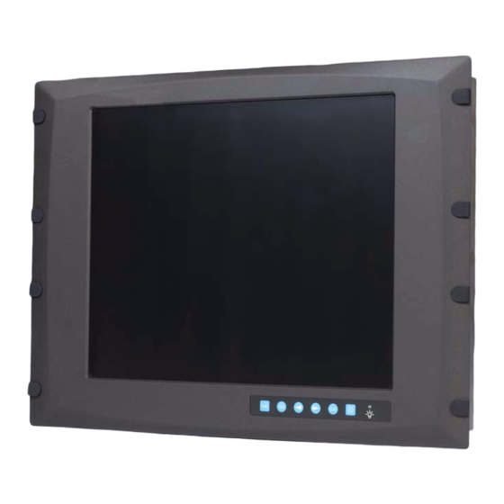
- Page 1 FPM-3170 Series Industrial Flat Panel Monitor with 17" LCD in VGA/Video User Manual...
- Page 2 Copyright This document is copyrighted by Advantech Co., Ltd. All rights are reserved. Advantech Co., Ltd. reserves the right to make improvements to the products described in this manual at any time. Spec- ifications are thus subject to change without notice.
- Page 3 FCC Class B This equipment has been tested and found to comply with the limits for a Class B digital device, pursuant to Part 15 of the FCC Rules. These limits are designed to provide reasonable protection against harmful interfer- ence when the equipment is operated in a residential environment.
- Page 4 Additional Information and Assistance 1.Visit the Advantech web site at www.advantech.com where you can find the latest information about the product. 2.Contact your distributor, sales representative, or Advantech's customer service center for technical support if you need additional assistance. Please have the following information ready before you call: •Product name and serial number...
-
Page 5: Safety Instructions
Safety Instructions 1. Read these safety instructions carefully. 2. Keep this User's Manual for later reference. 3. Disconnect this equipment from any AC outlet before cleaning. Use a damp cloth. Do not use liquid or spray detergents for cleaning. 4. For plug-in equipment, the power outlet socket must be located near the equip- ment and must be easily accessible. - Page 6 Der arbeitsplatzbezogene Schalldruckpegel nach DIN 45 635 Teil 1000 beträgt 70dB(A) oder weiger. DISCLAIMER: This set of instructions is given according to IEC704-1. Advan- tech disclaims all responsibility for the accuracy of any statements contained herein. FPM-3170 Series User Manual...
-
Page 7: Table Of Contents
Rack Mounting ............10 Figure 2.5:Rack Mounting ........... 10 Desktop Mounting............11 Figure 2.6:FPM-3170 Mounted on Desktop Stand ..11 Figure 2.7:A Complete Desktop Stand ......11 Swing Arm Mounting............12 Figure 2.8:Swing Arm for the FPM-3170 series ..12... - Page 8 Appendix A Touchscreen Driver Installation ....14 Introduction ..............14 Touchscreen Specifications..........14 A.2.1 Electrical ..............14 A.2.2 Optical ................14 A.2.3 Mechanical ..............14 A.2.4 Durability ..............14 A.2.5 Chemical Resistance ............ 15 Installation of Touchscreen Driver........15 Configuring PenMount Windows 2000/XP Driver..20 A.4.1 PenMount Control Panel ..........
- Page 9 Introduction This chapter includes: •Introduction •Specifications •LCD Specification •Connectors •Dimensions Chapter 1...
-
Page 10: Chapter 1 Introduction
Chapter 1 Introduction 1.1 Introduction Advantech's FPM-3170 Series consist of 17" color TFT LCD flat panel monitors built specifically for industrial applications. With the optional touchscreen, FPM-3170 monitors are excellent and user-friendly system control interfaces. The FPM-3170 Series includes the FPM-3170G and FPM-3171GA. -
Page 11: Touchscreen (Optional)
• Vibration (operating): 5 ~ 17 Hz, double-amplitude displacement 17 ~ 500 Hz, 1.0 G peak to peak • Dimensions: (W x H x D):482 x 354 x 68 mm (19" x 13.9" x 2.7") • Net Weight:12.7 kg (27.9 lb) •... -
Page 12: Connectors
USB port of the PC. The touchscreen cable is included with all orders which include the touchscreen option. DC 12 V Power in This connector will be connected to the DC 12V Switching Power Sup- ply. FPM-3170 Series User Manual... -
Page 13: Dimensions
1.5 Dimensions Cutout Dimensions: 451 x 340 mm (17.8" x 13.4") Figure 1.1: FPM-3170G Dimensions Chapter 1... -
Page 14: Figure 1.2:Fpm-3171Ga Dimensions
Figure 1.2: FPM-3171GA Dimensions FPM-3170 Series User Manual... -
Page 15: System Setup
System Setup This chapter includes: •Mounting the Monitor - Wall/Panel/Rack Mounting - Desktop Stand/Swing-ARM Mounting Chapter 2 System Setup... -
Page 16: Chapter 2 System Setup
Chapter 2 System Setup 2.1 Mounting the Monitor Monitors of the FPM-3170 series can be placed as you require. The versa- tility of the FPM-3170 mounts enable it to be mounted on your desk or anywhere else. 2.1.1 Wall Mounting With wall mounting brackets, the FPM-3170 monitors can be mounted directly to a wall. -
Page 17: Panel Mounting
2.1.2 Panel Mounting If you need to install the FPM-3170 series on a panel mount, please release the wall mounting brackets by detaching four screws on rear side and fix them on top and bottom sides by screws. Figure 2.3: Panel Mounting (cut out dimension: 451 x 340 mm) Figure 2.4: Bracket Arranged for Panel Mounting... -
Page 18: Rack Mounting
2.1.3 Rack Mounting The FPM-3170G series of monitors can be directly mounted to an indus- try standard 19" rack. There are four screw holes on each side of the panel. Figure 2.5: Rack Mounting FPM-3170 Series User Manual... -
Page 19: Desktop Mounting
2.2 Desktop Mounting You can place the desktop stand for desktop use or attach it on a swing- arm bracket. 2.2.1 Desktop Stand The desktop stand brackets (named mounting bracket in the packing list) can be found in the accessory box. Figure 2.6: FPM-3170 Mounted on Desktop Stand Attach the fix bracket on the bottom part of the FPM-3170. -
Page 20: Swing Arm Mounting
2.3 Swing Arm Mounting Detach the mounting brackets on the rear side, then attach the FPM-3170 series onto the Swing-ARM mount (75 or 100 mm square bracket). Figure 2.8: Swing Arm for the FPM-3170 series FPM-3170 Series User Manual... -
Page 21: Touchscreen Driver
Touchscreen Driver Installation •Introduction •Specification •Installation Appendix A Driver Installation... -
Page 22: Appendix A Touchscreen Driver Installation
Appendix A Touchscreen Driver Installation A.1 Introduction The FPM-3170 Series’ optional touchscreen uses an advanced 8-wire resistive technology. It provides more accurate sensing capacity than other technologies. The touchscreen is specially designed for tough industrial environments, and has been approved to FCC Class B stan- dards. -
Page 23: Chemical Resistance
10W30 Motor Oil, Diesel Fuel, Transmission Fluid, Brake Fluid, Anti- freeze, Hydraulic Oil. A.3 Installation of Touchscreen Driver The touchscreen in the FPM-3170 Series provides drivers for use with Windows 2000 and XP. For a detailed touchscreen drivers installation procedure, please refer to the folder:... - Page 24 Follow the steps below to install the PenMount Windows 2000/XP driver. When the system first detects the controller board, a screen appears that shows “Unknown Device.” Do not use this hardware wizard. Press Cancel. FPM-3170 Series User Manual...
- Page 25 Insert the PenMount Driver CD-ROM. Go to the Windows 2000- XP Driver folder. Click setup.exe. The screen displays the installation wizard for the PenMount soft- ware. Click “Next”. Appendix A Driver Installation...
- Page 26 A License Agreement appears. Click “I accept…” and “Next” The “Ready to Install the Program” screen appears. Select “Install.” FPM-3170 Series User Manual...
- Page 27 The next screen is “Hardware Installation.” Select “Continue Any- way.” The “InstallShield Wizard Completed” appears. Click “Finish.” Appendix A Driver Installation...
-
Page 28: Configuring Penmount Windows 2000/Xp Driver
Advanced Calibration uses 4, 9, 16 or 25 points to effec- Calibration tively calibrate touch panel linearity of aged touch screens. Click this button and touch the red squares in sequence with a stylus. To skip, press ‘ESC’. FPM-3170 Series User Manual... - Page 29 NOTE: The older the touch screen, the more Advanced Mode calibration points you need for an accurate calibration. Use a stylus during Advanced Calibration for greater accuracy. Appendix A Driver Installation...
- Page 30 FPM-3170 Series User Manual...
- Page 31 Plot Calibra- Check this function and a touch panel linearity com- tion Data parison graph appears when you have finished Advanced Calibration. The blue lines show linearity before calibration and black lines show linearity after calibration. Appendix A Driver Installation...
- Page 32 Touch the screen with your finger or a stylus and the drawing screen reg- isters touch activity such left, right, up, down, pen up, and pen down. Click Clear Screen to clear the drawing. FPM-3170 Series User Manual...
- Page 33 Multiple Monitors Multiple Monitors supports from two to six touch screen displays for one system. The PenMount drivers for Windows 2000/XP support Multiple Monitors. This function supports from two to six touch screen displays for one system. Each monitor requires its own PenMount touch screen control board, either installed inside the display or in a central unit.
- Page 34 When the mapping screen message appears, click OK. Touch each screen as it displays “Please touch this monitor.” Fol- lowing this sequence and touching each screen is called mapping the touch screens. FPM-3170 Series User Manual...
- Page 35 Touching all screens completes the mapping and the desktop reap- pears on the monitors. Select a display and execute the ‘Calibration’ function. A message to start calibration appears. Click OK. “Touch this screen to start its calibration” appears on one of the screens.
- Page 36 Beep on Pen Up – beep occurs when pen is lifted up Beep on both of Pen Down/Up – beep occurs on both Beep Frequency – modifies sound frequency Beep Duration – modifies sound duration FPM-3170 Series User Manual...
- Page 37 About This panel displays information about the PenMount controller and driver version. Appendix A Driver Installation...
-
Page 38: Penmount Monitor Menu Icon
Right and Left Button functions. Pen Sta- Check this function to reduce cursor vibration for relatively bilizer unstable touch screens, or where there may be excess vibration. Normally this function is not checked. Exit Exits the PenMount Monitor function. FPM-3170 Series User Manual... -
Page 39: Penmount Rotating Functions
A.4.3 PenMount Rotating Functions The PenMount driver for Windows 2000/XP supports several display rotating software packages. Please see Chapter 5 for more information. The PenMount drivers for Windows 95, Windows 98/Me, Windows 2000/XP, as well as Windows 98 USB and Windows Me/2000/XP sup- port display rotating software packages such as: •... - Page 40 FPM-3170 Series User Manual...
- Page 41 Supported Input Timing Modes...
-
Page 42: Appendix B Supported Input Timing Modes
Vsync, even in the case that the signals other than the preset timing that were entered. Note 3: Because adjustments may not fit, such as differing magnifying ratios or, in the case that you use it except for the display timing that was preset. FPM-3170 Series User Manual... - Page 43 OSD Operation Keypad...
-
Page 44: Appendix C Osd Operation
3. The auto setup procedure finishes. Note 4: If the OSD needs to be locked, press the < and > at the same time until the .Lock. indicator appears on the display. To unlock, repeat the same procedures once more. FPM-3170 Series User Manual... - Page 45 C.2 OSD Function Each selected value is stored into LCD memory after SEL signal input or time out. The stored values are not affected if the power is turned off. But the selected value is not available in case a selected mode is changed before time out or power is turned off before time out.
- Page 46 FPM-3170 Series User Manual...
Need help?
Do you have a question about the FPM-3170 Series and is the answer not in the manual?
Questions and answers