
Subscribe to Our Youtube Channel
Related Manuals for Advantech FPM-3150TVE Series


Summary of Contents for Advantech FPM-3150TVE Series
- Page 1 FPM-3150TVE Series Flat Panel Monitor with 15" Color TFT/LCD Display enchanced version User's Manual...
-
Page 2: Copyright Notice
Copyright Notice This document is copyrighted by Advantech Co., Ltd. All rights are reserved. Advantech Co., Ltd. reserves the right to make improvements to the products described in this manual at any time. Specifications are thus subject to change without notice. - Page 3 FCC Class B This equipment has been tested and found to comply with the limits for a Class B digital device, pursuant to Part 15 of the FCC Rules. These limits are designed to provide reasonable protection against harmful interference when the equipment is operated in a residential environment.
-
Page 4: Packing List
If any of these items are missing or damaged, contact your distributor or sales representative immediately. Additional Information and Assistance 1. Visit the Advantech web site at www.advantech.com where you can find the latest information about the product. 2. Contact your distributor, sales representative, or Advantech's customer service center for technical support if you need additional assistance. -
Page 5: Safety Instructions
The sound pressure level at the operator's position according to IEC 704-1:1982 is no more than 70dB(A). DISCLAIMER: This set of instructions is given according to IEC 704-1. Advantech disclaims all responsibility for the accuracy of any statements contained herein. -
Page 6: Wichtige Sicherheishinweise
- Wenn das Gerät deutliche Anzeichen eines Defektes aufweist. Der arbeitsplatzbezogene Schalldruckpegel nach DIN 45 635 Teil 1000 beträgt 70dB(A) oder weiger. DISCLAIMER: This set of instructions is given according to IEC704-1. Advantech disclaims all responsibility for the accuracy of any statements contained herein. FPM-3150TVE User's Manual... - Page 7 Introduction This chapter includes: • Introduction • Specifications • LCD Specification • Power Consumption • Connectors • Dimensions...
-
Page 8: Specifications
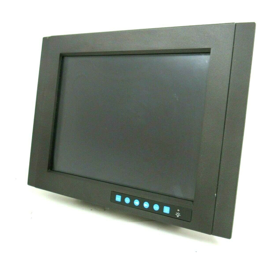
1.1 Introduction Advantech's FPM-3150TVE Series is a 15" color TFT LCD flat panel monitor built specifically for industrial applications. With the optional touchscreen, the FPM-3150TVE Series is an excellent and user-friendly system control interface. In addition to its usual application as an LCD panel monitor, the FPM-... -
Page 9: Lcd Specification
Touchscreen (Optional) • Type: 8 wire, analog resistive • Resolution: continuous • Light transmission: 75% (surface meets ASTM-D-3363-92A Standard, tabler abrasion test) • Operating Pressure: 30 ~ 45 gram for stylus pen, contact bounce < 10 ms • Controller: RS-232 interface •... -
Page 10: Dc 12V Power In
1.5 Connectors The following connectors are situated on the left hand side of the FPM-3150 Series: VGA Port (DB-15) This DB-15 connector can be connected to the system via the external 15-pin DB-15 connector locatd on the left side of the system unit. Touchscreen Connector (DB-9) (optional) This connector will be present only if a touchscreen is installed. - Page 11 1.6 Dimensions Figure 1-6: Dimensions Chapter 1 Introduction...
- Page 12 FPM-3150TVE User's Manual...
-
Page 13: System Setup
System Setup • Mounting the Monitor - Wall/Panel/Rack Mounting - Desktop Stand/Swing-ARM Mounting... -
Page 14: Mounting The Monitor
2.1 Mounting the Monitor The FPM-3150 Series can be placed as you require. The versatility of the FPM-3150 mounts enable it to be mounted on your desk or anywhere else. 2.1.1 Wall Mounting Thanks to wall brackets, the FPM-3150 can be mounted directly to a wall. -
Page 15: Panel Mounting
2.1.2 Panel Mounting If you need to install the FPM-3150 series on a panel mount, please release the mounting brackets by detaching four screws on rear side and fix them on up and bottom side by screws. Figure 2-2: Panel Mounting (cut out dimension: 396mm x 296mm) Chapter 2 System Setup... -
Page 16: Rack Mounting
2.1.3 Rack Mounting If you need to install the FPM-3150TVE on a rack, you must order the rack mount kit (4 pieces of brackets) for the FPM-3150TVE (Part Number is FPM-3150Rack-MT). Assemble the rack mount brackets on either side of FPM-3150TVE with 12 screws, then affix the monitor on the rack. -
Page 17: Desktop Stand
2.2 Desktop, Swing-ARM for FPM-3150TVE The FPM-3150 Series can be mounted in other ways. You can place the desktop stand for desktop use or attach it on a swing-arm bracket. 2.2.1 Desktop Stand The desktop stand bracket is attached to the rear of the FPM-3150. Simply detach the small bracket at the top of the monitor by unscrew- ing the two screws. - Page 18 2.2.2 Swing-ARM Detach the mounting brackets on the rear side, then attach the FPM- 3150 series onto the Swing-ARM mount (75mm or 100mm square bracket). Figure 2.5: Swing-ARM for the FPM-3150 series FPM-3150TVE User's Manual...
-
Page 19: Touch Screen Driver Installation
Touchscreen Driver Installation • Introduction • Specification • Installation - for Windows 95/98 - for Windows NT/2000... - Page 20 A.1 Introduction The FPM-3150 Series’ optional touchscreen uses an advanced 8-wire resistive technology. It provides more accurate sensing capacity than other technologies. The touchscreen is specially designed for tough industrial environments, and has been approved to FCC Class A and Class B standards.
-
Page 21: Sensor Board
Optical • Visible light transmission: 75% (typical) • Reflection: > 25% @ 550 nm Sensor board • Chemical strengthened glass meets “4H” hardness standard (Test condition: ASTM D3363-92A) Ball drop test • Touchscreen can withstand a 225 g steel ball dropped from a height of 660 mm, without breaking Environmental •... -
Page 22: Installation For Windows 95
A.3.1 Installation for Windows 95/98 1. A. Select Start menu and then click Run B. Type D:\fpm\touchdrv\penmount\win9xv3.3\setup.exe C. Press OK D. Follow the instructions for the setup process 2. A. Click the Detect button B. Press OK and the system will reboot FPM-3150TVE User's Manual... - Page 23 3. A. After the system reboots, click Start, Programs, PenMount Utilities, PenMount Control Panel B. Select the Calibrate tab C. Click the Calibrations button on the right 4. A. Use a soft stylus to press the little red dot located above the finger icon B.
-
Page 24: Installation For Windows Nt
5. Press OK A.3.2 Installation for Windows NT 1. A. Select Start menu and then click Run B. Type D:\fpm\touchdrv\penmount\winnt-ver3.11\setup.exe C. Press OK D. Follow the instructions for the setup process FPM-3150TVE User's Manual... - Page 25 2. A. Click the Detect button B. Press OK and the system will reboot 3. A. After the system reboots, click Start, Programs, PenMount Utilities, PenMount Control Panel B. Select the Calibrate tab C. Click the Calibrations button on the right Appendix A Touchscreen Driver Installation...
- Page 26 4. A. Use a soft stylus to press the little red dot located above the finger icon B. Repeat the process according to the sequence: top, right, bottom, and left 5. Press OK FPM-3150TVE User's Manual...
-
Page 27: Installation For Windows 2000
A.3.3 Installation for Windows 2000 1. A. Select Start menu and then click Run B. Type D:\fpm\touchdrv\penmount\win2000v1.0\setup.exe C. Press OK D. Follow the instructions for the setup process 2. A. Click the Detect button B. Press OK and the system will reboot Appendix A Touchscreen Driver Installation... - Page 28 3. A. After the system reboots, click Start, Programs, PenMount Utilities, PenMount Control Panel B. Select the Calibrate tab C. Click the Calibrations button on the right 4. A. Use a soft stylus to press the little red dot located above the finger icon B.
- Page 29 5. Press OK Appendix A Touchscreen Driver Installation...
- Page 30 A.3.4 Installation for DOS A.3.4.1 Using HMI CD Driver to install PenMount software driver. A.Insert the driver CD toCD-ROM drive. B. Type "D:\fpm\touchdrv\penmount\win31&dos\install" C. A pop-up window will display "Salt International Corp. PenMount Install Utilities. Press ENTER key to allow PenMount install the drivers to drive C or use keyboard to key-in the hard disk drive that you plan to install the driver."...
- Page 31 If you do not need to detect IRQ5 and IRQ9, the command is: C:\PENMOUNT\PMDETECT -N5 -N9 A.3.4.3 Do Calibration A.To adjust touch screen mapping properly for the display, use PM.BAT (C:\PENMOUNT\PM ) tocalibration. B. Choose “1” DO CALIBRATION (adjust screen mapping). C.
-
Page 32: Penmount Dos Driver Functions
“PENMOUNT” directory can also be applied. Now, the PenMount DOS driver is installed. A.3.4.6 PenMount DOS driver functions There are several functions in the PenMount DOS driver. The user is able to change the settings of the following utilities: ??Show Current Setting A.The current setting data could be found from PM.BAT file. - Page 33 Standard Timing Set Serial Data for Expansion...
-
Page 34: Setting Serial Data For Expansion
B.1 Setting serial data for expansion The fourteen kinds of timings below are already programmed in this module. The input synchronous signals are automatically recognized. Note 1: Even if the preset timing is entered, a little adjust- ment of the functions such as Horizontal period, CLK-delay and display position, are required. - Page 35 Appendix B Standard Timing 29...
- Page 36 FPM-3150 Series User's Manual...
- Page 37 • OSD Selection • Keypad Interface • OSD Function...
-
Page 38: Keypad Interface
C.1 Keypad Interface The keypad interface provides driver for a dual color LED for status indication. PS, The green light means that the COMMON board detects the input signal and ends output signal to LCD panel . FPM-3150 Series User's Manual... -
Page 39: Osd Function
C.2 OSD Function Each selected value is stored into LCD memory after SEL signal input or time out. The stored values are not affected if the power is turned off. But the selected value is not available in case a selected mode is changed before time out or power is turned off before time out. - Page 40 FPM-3150 Series User's Manual...
Need help?
Do you have a question about the FPM-3150TVE Series and is the answer not in the manual?
Questions and answers