Table of Contents
Advertisement
Methods and apparatus disclosed and described herein have been developed solely on company funds of Lake Shore Cryotronics, Inc.
No government or other contractual support or relationship whatsoever has existed which in any way affects or mitigates proprietary
rights of Lake Shore Cryotronics, Inc. in these developments. Methods and apparatus disclosed herein may be subject to U.S. Patents
existing or applied for. Lake Shore Cryotronics, Inc. reserves the right to add, improve, modify, or withdraw functions, design
modifications, or products at any time without notice. Lake Shore shall not be liable for errors contained herein or for incidental or
consequential damages in connection with furnishing, performance, or use of this material.
Rev. 1.3
User's Manual
Model 330
Model 330
Model 330
Model 330
Autotuning
Temperature Controller
Includes Coverage For:
Model 330-1X – Silicon Diode
Model 330-2X – Platinum Resistor
Model 330-3X – GaAlAs Diode
Model 330-4X – Thermocouple
Model 330-5X – Thermocouple
Lake Shore Cryotronics, Inc.
575 McCorkle Blvd.
Westerville, Ohio 43082-8888 USA
E-Mail Addresses:
sales@lakeshore.com
service@lakeshore.com
Visit Our Website:
www.lakeshore.com
Fax: (614) 891-1392
Telephone: (614) 891-2243
P/N 119-009
15 November 2000
Advertisement
Table of Contents

Related Manuals for Lakeshore 330


Summary of Contents for Lakeshore 330
- Page 1 Model 330 Model 330 Model 330 Autotuning Temperature Controller Includes Coverage For: Model 330-1X – Silicon Diode Model 330-2X – Platinum Resistor Model 330-3X – GaAlAs Diode Model 330-4X – Thermocouple Model 330-5X – Thermocouple Lake Shore Cryotronics, Inc. 575 McCorkle Blvd.
- Page 2 FIRMWARE LIMITATIONS Lake Shore has worked to ensure that the Model 330 firmware is as free of errors as possible, and that the results you obtain from the instrument are accurate and reliable. However, as with any computer-based software, the possibility of errors exists.
-
Page 3: Declaration Of Conformity
Lake Shore Model 330 Autotuning Temperature Controller User’s Manual Declaration of Conformity Lake Shore Cryotronics, Inc. 575 McCorkle Blvd. Westerville, OH 43082-8888 USA hereby declare that the equipment specified conforms to the following Directives and Standards: Application of Council directives:... - Page 4 Emissions of and immunity to electromagnetic interference is now part of the design and manufacture of most electronics. To qualify for the CE mark, the Model 330 meets or exceeds the generic requirements of the European EMC directive 89/336/EEC. The instrument was tested under normal operating conditions with sensor and interface cables attached.
-
Page 5: Table Of Contents
Lake Shore Model 330 Autotuning Temperature Controller User’s Manual TABLE OF CONTENTS Chapter/Paragraph Title Page INTRODUCTION ............................1-1 General..........................1-1 Model 330 Temperature Controller Description ..............1-2 Control Fundamentals and Autotune...................1-5 Precision Calibration Options ....................1-6 Electrostatic Discharge......................1-6 1.4.1 Identification of Electrostatic Discharge Sensitive Components ........1-6 1.4.2... -
Page 6: Chapter/Paragraph Title Page
Lake Shore Model 330 Autotuning Temperature Controller User’s Manual Chapter/Paragraph Title Page 3.2.7 SoftCal ..........................3-5 3.2.7.1 SoftCal Errors ....................... 3-5 3.2.7.2 Customer-Performed SoftCal ..................3-6 3.2.7.3 Entering Voltage Values from a Lake Shore SoftCal Report........3-6 Control Functions ........................ 3-8 3.3.1... - Page 7 Lake Shore Model 330 Autotuning Temperature Controller User’s Manual Chapter/Paragraph Title Page IEEE-488/Serial Interface Command Summary..............4-10 4.3.1 Command List Structure ....................4-10 4.3.2 Common Commands .....................4-11 4.3.3 Interface Commands......................4-13 4.3.4 Display Commands ......................4-14 4.3.5 Control Process Commands ..................4-16 4.3.6 Curve Commands ......................4-19 User Curve Loading Program....................4-23...
- Page 8 Lake Shore Model 330 Autotuning Temperature Controller User’s Manual LIST OF ILLUSTRATIONS Figure No. Title Page Model 330 Temperature Controller Front Panel ................1-2 Model 330 Block Diagram ........................ 1-5 Cryogenic Storage Dewar ........................ 1-7 Typical Model 330 Rear Panel ......................2-2 Heater Jumper (JMP9)........................
-
Page 9: Introduction
Westerville, Ohio 43082-8888. This manual is subject to change without notice. Due to our commitment to continuous product improvement, we may modify the Model 330 software with time. Some changes result from Customer feedback regarding operation on various cryogenic systems. Please contact us with any observations or suggestions regarding the use of this controller. -
Page 10: Model 330 Temperature Controller Description
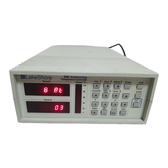
The Model 330 bright red dual LED display shows data from both sensors, or one sensor and the setpoint. It displays temperature in K, °C, or sensor units in volts (V), millivolts (mV), or ohms (Ω). Heater output current always displays on a separate bar graph. - Page 11 Lake Shore Model 330 Autotuning Temperature Controller User’s Manual Table 1-1. Electronic Information for Various Sensors and Temperature Ranges Suffix Sensor Type Silicon Diode 100Ω Platinum RTD GaAlAs Diode Thermocouple Sensor Temperature Coefficient Negative Positive Negative Positive Sensor Units Volts (V) Ohms (Ω)
-
Page 12: Model 330 Specifications
Conditioner, heater noise is lowered by 20 dB) Front Panel: Display: Two, 4.5 digit LED Display Units: Temperature in K or °C. Sensor units in volts (330-1X & -3X), ohms (330-2X), or millivolts (330-4X) Setpoint display: Shared with control sensor Heater output display:... -
Page 13: Control Fundamentals And Autotune
Lake Shore Model 330 Autotuning Temperature Controller User’s Manual Power Supply AC Line Analog Digital Display Current Channel 4-Lead Source A Sensor Micro- Keypad Controller Current Source B IEEE-488 Interface Converter 16-Bits Program RS-232C 4-Lead PROM Channel Interface Sensor Converter... -
Page 14: Precision Calibration Options
Lake Shore Model 330 Autotuning Temperature Controller User’s Manual PRECISION CALIBRATION OPTIONS The Lake Shore Precision Calibration Option converts calibrated sensor data into breakpoint pairs readable by the controller program. The Precision Calibration Option is available in three forms: the Model 8000 loads the breakpoint pairs on a floppy disk in ASCII format for Customer downloading;... -
Page 15: Handling Liquid Helium And Liquid Nitrogen
Lake Shore Model 330 Autotuning Temperature Controller User’s Manual HANDLING LIQUID HELIUM AND LIQUID NITROGEN Liquid Helium (LHe) and liquid nitrogen (LN ) may be used in conjunction with the Model 330. Although LHe and LN are not explosive, there are certain safety considerations when handling them. -
Page 16: Safety Summary
Lake Shore Cryotronics, Inc. assumes no liability for Customer failure to comply with these requirements. The Model 330 protects the operator and surrounding area from electric shock or burn, mechanical hazards, excessive temperature, and spread of fire from the instrument. Environmental conditions outside of the conditions below may pose a hazard to the operator and surrounding area. -
Page 17: Installation
Lake Shore Warranty on the A Page (immediately behind the title page). REPACKAGING FOR SHIPMENT To return the Model 330, sensor, or accessories for repair or replacement, obtain a Return Goods Authorization (RGA) number from Technical Service in the United States, or from the authorized sales/service representative from which the product was purchased. -
Page 18: Definition Of Rear Panel Connections
Lake Shore Model 330 Autotuning Temperature Controller User’s Manual DEFINITION OF REAR PANEL CONNECTIONS The Model 330 rear panel consists of the power and fuse assembly, IEEE-488 Interface Connector, Serial I/O Connector, two Sensor Input connectors, and Heater Output Connections. -
Page 19: Sensor Input Settings
Grounding and shielding signal lines are major setup concerns. The Model 330 allows 4-wire measurement of diode voltage and resistance. To prevent inaccuracy, isolate diode and resistive sensor leads from earth ground. -
Page 20: Sensor Installation
Quad-Twist™ wire (or equivalent) for four-wire applications. 6. Thermally anchor lead wires. See Paragraph 2.7.1 for installing Diode (Model 330-1X) and Platinum (Model 330-2X) sensors, Paragraph 2.7.2 for Thermocouple (Model 330-4X) sensors, and Paragraph 2.7.3 for sensor input error messages. -
Page 21: Heat Sinking Sensor Leads
For the Model 330-2X, Series PT-100 Platinum Sensors follow the same procedures for diode type sensors. The difference is Platinum sensors have no lead polarity and some materials used at cold temperatures will not tolerate the high temperature range of the Platinum sensor. -
Page 22: Measurement Errors Due To Ac Noise
When a new or different thermocouple is attached to the controller, adjust the offset to compensate for discrepancies in thermocouple material, leads, and connections. Offset adjustment trimpots are provided inside the Model 330 to allow offset calibration of the thermocouple. See Paragraph 5.12. 2.6.2.2 Thermocouple Wire Types at Cryogenic Temperatures Below are recommended thermocouple wire types for cryogenic temperatures. -
Page 23: Sensor Input Error Messages
Table 2-3 lists the standard curves with curve number and temperature range. If a curve with the wrong temperature coefficient (slope) is selected, the Model 330 selects the default curve for the sensor type. -
Page 24: Precision Calibration Option
Shore stores the calibration data in a NOVRAM and sends the programmed IC to the customer. The IC is then installed in the instrument by the customer. The user must supply the Model 330 serial number at the time of order. -
Page 25: Heater Setup
2.10 RACK MOUNTING The Model 330 ships with plastic “feet,” ready for use as a bench instrument. As an option, the Model 330 installs in a standard 19 inch instrument rack. For information on the optional Model 3022 Half-Rack Mounting Kit for a single controller, see Paragraph 6.3 and Figure 6-4. -
Page 26: Power Up (Pup) Configuration
2.11.2 Power Up Configuration The user may store a Model 330 Power Up (PUP) configuration so the Model 330 powers up to a user-defined state after power down. Retain heater range, setpoint, gain, reset, units, and curve number store in non- volatile memory even when the line cord is disconnected. -
Page 27: Operation
Lake Shore Model 330 Autotuning Temperature Controller User’s Manual CHAPTER 3 OPERATION GENERAL This chapter covers Definition of Front Panel Controls (Paragraph 3.1), Thermometry Functions (Paragraph 3.2), Control Functions (Paragraph 3.3), Interface and Miscellaneous Functions (Paragraph 3.4), and Thermocouple Controller Operation (Model 330-04 only, Paragraph 3.5). -
Page 28: Front Panel Led Display
Figure 3-2. Definition of Front Panel LED Display THERMOMETRY FUNCTIONS The following front panel keyboard functions relate to Model 330 thermometry: Input Type (Paragraph 3.2.1), Channel (Paragraph 3.2.2), Units (Paragraph 3.2.3), Temperature Compensation (Paragraph 3.2.4), Display Filter (Paragraph 3.2.5), Curve (Paragraph 3.2.6), and SoftCal (Paragraph 3.2.7). -
Page 29: Input Type
For silicon and GaAlAs diodes (Models 330-1X and -3X respectively), the additional units selection is Volts (V). For the Platinum RTDs (Model 330-2X), the additional units selection is ohms (Ω). For the thermocouple (Model 330-4X), the additional units selection is millivolts (mV). Units in K is the default for all models. -
Page 30: Display Filter
User-Defined Curves or Precision Option Calibrations. Increased resolution (more data points) version of Curve 10. Used by the Model 330 to generate a SoftCal Curve. † Values are for thermocouples with compensation. Uncompensated, the thermocouple can use the full ±15 mV range. -
Page 31: Softcal
(see Paragraph 3.2.6.3). With either method, the Model 330 creates a new curve for this specific diode and stores it as Curve 11 thru 31 in controller memory. This procedure can make an inexpensive Band 13 diode more accurate than our tightest Band 11 diode. -
Page 32: Customer-Performed Softcal
Lake Shore Model 330 Autotuning Temperature Controller User’s Manual 3.2.7.2 Customer Performed SoftCal Depending on the desired temperature range, the Customer may perform a 2-point or 3-point SoftCal. This example assumes a 3-point SoftCal. For 2-point, omit the steps associated with reading the voltage at 4.2 K. -
Page 33: Sensor Calibrations And Precision Options
Lake Shore Model 330 Autotuning Temperature Controller User’s Manual Lake Shore DT-400 Series With regards to accuracy, there are 3 things that can be done Silicon Diode Temperature Sensor with a temperature sensor: Precision SoftCal™ Standard Calibration Calibration Standard sensors are Lake Shore can do a precision A Lake Shore Sof tCal™... -
Page 34: Control Functions
Escape to cancel and retain the previous value. Also use either s or t to increment or decrement the display by one degree. The setpoint on the Model 330 is limited to a resolution of 0.01 for temperatures below 200 and 0.1 for temperatures greater than 200. Any decimal digits entered after the 100 place are ignored. -
Page 35: Voltage Resolution (Models 321-1X, -3X, & -4X Only)
3.3.4 Autotune There are three Model 330 automatic tuning modes: Auto P, Auto PI, and Auto PID. The Autotuning algorithm determines proper settings for Gain (Proportional), Reset (Integral) and Rate (Derivative) by observing system time response upon changes in setpoint under either P, PI or PID control. -
Page 36: Initial Values Of Pid Parameters In Autotuning Mode
Lake Shore Model 330 Autotuning Temperature Controller User’s Manual 3.3.4.1 Initial Values of PID Parameters In Autotune Mode Initial values of PID parameters in Autotune mode are set when the controller is changed from Manual to either P, PI or PID control. Initial factory settings are Autotuning PI where P = 50 and I = 20, which corresponds to 20 repeats per 1000 seconds or an equivalent time constant of 1000/20 or 50 seconds. -
Page 37: Setting Rate (Derivative)
3.3.6 Zone Setting The Model 330 allows up to 10 custom temperature zones where the controller automatically uses pre- programmed PID settings and heater range. Configure the zones using 01 as the lowest to 10 as the highest zone in K. Copy Figure 3-4 to plan zones, then use the manual to record final zone settings. Paragraph 3.4.4 lists default zones. -
Page 38: Record Of Zone Settings
Lake Shore Model 330 Autotuning Temperature Controller User’s Manual Zone Setting WorkSheet Zone 10 Setpoint: Heater Range P (1-999) I (1-999) D (1-200) Off Low High Zone 09 Setpoint: Heater Range P (1-999) I (1-999) D (1-200) Off Low High... -
Page 39: Interface And Miscellaneous Functions
Lake Shore Model 330 Autotuning Temperature Controller User’s Manual INTERFACE AND MISCELLANEOUS FUNCTIONS The following front panel keyboard functions relate to Model 330 thermometry or temperature control: Baud (Paragraph 3.4.1), Address (Paragraph 3.4.2), Local (Paragraph 3.4.3), Defaults/Reset (Paragraph 3.4.4), and Power Up Configuration (PUP, Paragraph 3.4.5). -
Page 40: Power Up (Pup) Configuration
3.4.5 Power Up (PUP) Configuration Sample Store a Model 330 Power Up (PUP) configuration to ensure that it powers up to a user-defined state after power down. Parameters including heater range, setpoint, gain, reset, units, and curve number store in non-volatile memory and are retained even when the line cord is disconnected. -
Page 41: Thermocouple Controller Operation (Model 330-4X Only)
The Model 330 operates on sensor curve data ranging from 0.00000 to 3.00000 volts. Convert thermocouple voltage to this range before entering it into a curve table. To obtain the proper table value from a thermo- couple voltage, sum it with 15 millivolts to make it positive and multiply it by 100 to shift the resolution. - Page 42 Lake Shore Model 330 Autotuning Temperature Controller User’s Manual This Page Intentionally Left Blank 3-16 Operation...
-
Page 43: Remote Operation
REMOTE OPERATION GENERAL Either of the two computer interfaces provided with the Model 330 permit remote operation. The first is the IEEE-488 Interface (Paragraph 4.1). The second is the Serial Interface (Paragraph 4.2). The two interfaces share a common set of commands (Paragraph 4.3). Use only one of the interfaces at a time. See Paragraph 4.4 for a Serial Interface curve loading program. -
Page 44: Bus Control Commands
There are two status registers: the Status Byte Register (Paragraph 4.1.3.1), and the Standard Event Status Register (Paragraph 4.1.3.2). 4.1.3.1 Status Byte Register and Service Request Enable Register The Status Byte Register consists of one data byte containing six bits of information about Model 330 status. STATUS BYTE REGISTER FORMAT Bit – Weighting –... - Page 45 The bit will not revert to zero if the reading falls back outside the chosen limit. If this report is read and the control sensor reading is still inside the limit, the Model 330 sets the CLE bit again. Enter the control channel limit with the CLIM device dependent command.
-
Page 46: Example Ieee Setup And Program
Example IEEE Setup and Program Below is an example of how to setup and run a simple program using the built-in Model 330 IEEE-488 Interface. It does not reflect every hardware/software configuration found in the field. This example uses the National Instruments GPIB - PCII/IIA card and QuickBasic 4.0 or 4.5 on a PC compatible. -
Page 47: Sample Basic Ieee-488 Interface Program
Lake Shore Model 330 Autotuning Temperature Controller User’s Manual Table 4-1. Sample BASIC IEEE-488 Interface Program IEEEEXAM.BAS EXAMPLE PROGRAM FOR IEEE-488 INTERFACE This program works with QuickBasic 4.0/4.5 on an IBM PC or compatible. The example requires a properly configured National Instruments GPIB-PC2 card. The REM $INCLUDE statement is necessary along with a correct path to the file QBDECL.BAS. -
Page 48: Typical National Instruments Gpib Configuration From Ibconf.exe
Lake Shore Model 330 Autotuning Temperature Controller User’s Manual National Instruments GPIB0 Configuration GPIB-PC2/2A Ver 2.1 ↑ Primary GPIB Address ..→0 Select the primary GPIB address by using the left and right arrow keys. Secondary GPIB Address ..NONE Timeout setting ..... 10sec... -
Page 49: Serial I/O Interface
• Only QIDN? and QRST Common Commands are usable. • Terminators are fixed to CRLF. • A query must be added to the end of a command string if the Model 330 must return information. (Over IEEE-488, the last query response is sent when addressed to talk.) •... -
Page 50: Serial Interface Hardware Configuration
Serial Interface Hardware Configuration The Model 330 operates at two different Baud rates: 300 or 1200. Hold the Baud key and press the t key to cycle between 300 and 1200. The remaining communication parameters are fixed as defined in Table 4-3. - Page 51 Lake Shore Model 330 Autotuning Temperature Controller User’s Manual Table 4-3 Sample BASIC Serial Interface Program SEREXAM.BAS EXAMPLE PROGRAM FOR SERIAL INTERFACE This program works with QuickBasic 4.0/4.5 or Qbasic on an IBM PC or compatible with a serial interface. It uses the COM1 communication port at 1200 BAUD. Enter an instrument command or query at the prompt.
-
Page 52: Ieee-488/Serial Interface Command Summary
Lake Shore Model 330 Autotuning Temperature Controller User’s Manual IEEE-488/SERIAL INTERFACE COMMAND SUMMARY The IEEE-488/Serial Interface commands are listed alphabetically in function order. There are five command groups: Common Commands (Paragraph 4.3.2), Interface Commands (Paragraph 4.3.3), Display Commands (Paragraph 4.3.4), Control Process Commands (Paragraph 4.3.5), and Curve Commands (Paragraph 4.3.6). -
Page 53: Common Commands
*ESR? Returned: <ESR bit weighting>. Format: nnn[term] Remarks: Queries for various Model 330 error conditions and status. The integer returned represents the sum of the bit weighting of the event flag bits in the Standard Event Status Register. Q Q Q Q IDN? - Page 54 Q Q Q Q TST? Query Self-Test Input: *TST? Returned: 0 or 1. Format: n[term] Remarks: The Model 330 performs a self-test at power-up. 0 = no errors found, 1 = errors found. Q Q Q Q WAI Wait-to-Continue Input: *WAI Returned: Nothing Remarks: Prevents execution of any further commands or queries until completion of all previous ones.
-
Page 55: Interface Commands
Returned: Nothing Remarks: Sets the Model 330 mode: 0 = Local Mode, 1 = Remote Mode, 2 = Remote Mode with Local Lockout. Press the front panel Local key to set the Model 330 to local provided the key has not been disabled by local lockout. -
Page 56: Display Commands
Remarks: Set control channel units: K = kelvin, C = Celsius, S = appropriate sensor units (volts, ohms, or millivolts). Example: If operating in kelvin with a Model 330-01, CUNI S[term] makes the units volts – the sensor units for a diode sensor. The Model 330-02 platinum controller has sensor units of ohms, and the Model 330-04 thermocouple controller has sensor units of millivolts. - Page 57 Remarks: Set sample channel: K = kelvin, C = Celsius, S = appropriate sensor units (volts for diodes, ohms for RTDs, or millivolts for thermocouples). Example: If operating in kelvin with a Model 330-11, SUNI S[term] makes the units volts – the sensor units for a diode sensor.
-
Page 58: Control Process Commands
GAIN XXX Returned: Nothing Remarks: Enter an integer from 0 to 999. Example: GAIN 65 [term] instructs the Model 330 to set control gain to 65. Gain corresponds to the Proportional (P) portion of the PID Autotuning control algorithm. GAIN? Gain Query. - Page 59 Input: RAMPR XX.X Returned: Nothing Remarks: XX.X is the ramp rate in Kelvin per minute between 0 and 99.9. Example: RAMP 10[term] instructs the Model 330 to make the ramp rate equal to 10 K/Min. RAMPR? Ramp Rate Query. Input: RAMPR? Returned: XX.X...
- Page 60 Heater High. Use the TUNE command to activate the zone autotuning mode. Example: ZONE 1,100.0,2,100.0,100,20[term] instructs the Model 330 to store in Zone 1 a 100.0 K setpoint, a 2 (Medium) Heater Range, a 100 Gain, a 100 Reset, and a 20% Rate.
-
Page 61: Curve Commands
Room Temperature Compensation for Channel A Query. Input: ACOMP? Returned: 0 or 1 Remarks: Effective only with the Model 330-4X Thermocouple Version. Returns current room temperature compensation status: 0 = off, 1 = on. ACUR Assign Curve Number for Channel A. - Page 62 (0.00000). The table below gives the conversion of raw units into the format required. The Model 330 automatically fills in leading and trailing zeros. The second value is the temperature with three characters before the decimal point and one after it (000.0).
- Page 63 When entering, omit temperature coefficient, number of points, and endpoints. The Model 330 determines and stores whether the curve is a positive or negative coefficient curve. Based on temperature coefficient, the Model 330 then stores the curve end points and also adds the number of points.
- Page 64 ZZZ.Z = temperature in kelvin. Data points in Curves 00 thru 10 cannot be edited. If the Model 330 does not recognize either the units value or the temperature value, it assumes you are entering a new point and places it in the proper ascending position.
-
Page 65: User Curve Loading Program
Lake Shore Model 330 Autotuning Temperature Controller User’s Manual USER CURVE LOADING PROGRAM To simplify the loading of a user curve using the Serial Interface, the following curve loading program is provided. The program will work with QuickBASIC V4.0/4.5 or QBasic for use on an IBM PC or compatible with serial interface. - Page 66 Lake Shore Model 330 Autotuning Temperature Controller User’s Manual '************************************************************************ CURVE LOADING PROGRAM This routine will load a curve. Get here by entering "CURVE" above. * NOTE: SPACING OF THE DATA STRING IS VERY CRITICAL. For this example the string data must be on a single line of an ASCII file using the same format as the attached sample.*...
- Page 67 Lake Shore Model 330 Autotuning Temperature Controller User’s Manual Below are sample outputs from the program: Sample ACSII File No. 1 (Older DRC Sensor Format) XC06,S00TG120ACS2 8333,0.86045,325.0,0.90212,310.0,0.94350,295.0,0.98457,280.0,1. 02532,265.0,1.06566,250.0,1.09231,240.0,1.11874,230.0,1.14489,220.0,1.15784,215.0 ,1.17072,210.0,1.18349,205.0,1.19616,200.0,1.20869,195.0,1.22109,190.0,1.23331,18 5.0,1.24534,180.0,1.25717,175.0,1.26875,170.0,1.28009,165.0,1.29116,160.0,1.30194 ,155.0,1.31241,150.0,1.32258,145.0,1.33241,140.0,1.34192,135.0,1.35108,130.0,1.35 991,125.0,1.36840,120.0,1.37657,115.0,1.38440,110.0,1.39189,105.0,1.39908,100.0,1 .40597,095.0,1.41258,090.0,1.41894,085.0,1.42509,080.0,1.43712,070.0,1.44327,065. 0,1.44993,060.0,1.45288,058.0,1.45611,056.0,1.45973,054.0,1.46394,052.0,1.46904,0 50.0,1.47551,048.0,1.48412,046.0,1.49606,044.0,1.51300,042.0,1.53706,040.0,1.5525 0,039.0,1.57064,038.0,1.59183,037.0,1.61638,036.0,1.64461,035.0,1.67679,034.0,1.7 1316,033.0,1.75390,032.0,1.79917,031.0,1.84902,030.0,1.90348,029.0,1.96261,028.0, 2.02646,027.0,2.09484,026.0,2.16753,025.0,2.24441,024.0,2.32537,023.0,2.41034,022 .0,2.49920,021.0,2.63876,019.5,2.83726,017.5,3.05000,015.5,3.27618,013.5,3.51800, 011.5,3.71192,010.0,3.91739,008.5,4.13945,007.0,4.36487,005.6,4.57772,004.4,4.829 63,003.1,5.03503,002.1,5.12385,001.6,5.15376,001.4*...
- Page 68 Lake Shore Model 330 Autotuning Temperature Controller User’s Manual This Page Intentionally Left Blank 4-26 Remote Operation...
-
Page 69: Service And Calibration
1. Clean front and back panels and case with soft cloth dampened with mild detergent and water solution. NOTE: Do not use aromatic hydrocarbons or chlorinated solvents to clean the Model 330. They may react with the plastic materials in the controller or the silk screen printing on the back panel. -
Page 70: Rear Panel Connector Definitions
Lake Shore Model 330 Autotuning Temperature Controller User’s Manual REAR PANEL CONNECTOR DEFINITIONS Figures 5-2 thru 5-4 define Serial I/O, Analog Output, Sensor input, and Heater Output connectors. SERIAL DESCRIPTION RS-232C In (RxD) RS-232C In (RxD) RS-232C Ground RS-232C Ground... -
Page 71: Ieee-488 Interface Connector
Lake Shore Model 330 Autotuning Temperature Controller User’s Manual IEEE-488 INTERFACE CONNECTOR Connect to the IEEE-488 Interface connector on the Model 330 rear with cables specified in the IEEE-488- 1978 standard document. The cable has 24 conductors with an outer shield. The connectors are 24-way Amphenol 57 Series (or equivalent) with piggyback receptacles to allow daisy-chaining in multiple device systems. -
Page 72: Optional Serial Interface Cable And Adapters
Lake Shore Model 330 Autotuning Temperature Controller User’s Manual OPTIONAL SERIAL INTERFACE CABLE AND ADAPTERS To aid in Serial Interface troubleshooting, Figures 5-6 thru 5-8 show wiring information for the optional cable assembly and the two mating adapters. YELLOW GREEN BLACK Figure 5-6. -
Page 73: Top Of Enclosure Remove And Replace Procedure
OPERATING SOFTWARE EPROM AND PRECISION OPTION NOVRAM REPLACEMENT The operating software for the Model 330 is contained on two Erasable Programmable Read Only Memory (EPROM) Integrated Circuits (ICs). The reference designator for the master EPROM is U11 (DC.HEX) and the slave is U16 (SV.HEX). -
Page 74: Error Messages
OL indicates the overload. If no signal or a wrong polarity signal exists at the input leads, Er27 indicates a Zero Error for Channel A or Er28 for Channel B. The Model 330 displays dashes “ - - - ” if the input switches are improperly set. -
Page 75: Changing Sensor Input Type
Zero Calibration. TEST 13. Configure the Model 330 to display Channel A in ohms (Ω). 14. Adjust R6 until the display reads 0.000 Ω (toggles to error). 15. Repeat Steps 11 – 14 for Channel B, except adjust R8. -
Page 76: Typical Model 330 Pcb Layout
Lake Shore Model 330 Autotuning Temperature Controller User’s Manual New C-330-U-5-9 Figure 5-9. Typical Model 330 PCB Layout Service & Calibration... -
Page 77: 5.11 Model 330-4X (Thermocouple) Calibration
2. Place the thermocouple in a reference bath of known temperature (liquid nitrogen, ice, etc.). Allow the system to stabilize to the reference temperature. 3. On the Model 330 front panel, select the thermocouple input and the desired temperature units. 4. Turn on thermocouple compensation. - Page 78 Lake Shore Model 330 Autotuning Temperature Controller User’s Manual This Page Intentionally Left Blank 5-10 Service & Calibration...
-
Page 79: Options And Accessories
Use the model numbers above to specify input type (e.g., 330-12 for a Model 330 with one Silicon Diode input and one Platinum input). The standard 330 heater output is 25 watts. Add a suffix of W50 to the order number for a unit factory-configured for 50 watts operation, or the user can do so by moving a jumper within the unit. - Page 80 999.9 K. The temperature at full scale, 1273 K, should be loaded as 636.5. The first three characters of the description field must be S99, this sequence tells the Model 330 that it has a -51 configuration.
-
Page 81: Accessories
Half-Rack Mounting Kit for One Model 330 Temperature Controller. Half-length mounting panel and RM-3H1 mounting ears to attach one Model 330 to a 482.6 mm (19-inch) by 88.9 mm (3.5 inch) rack mount space. See Figure 6-4. Half-Rack Mounting Kit for One Model 330 Temperature Controller with Handles. Half-length mounting RM-3H1-H panel, mounting ears, and handles to attach one Model 330 to a 482.6 mm (19-inch) by 88.9 mm (3.5 inch) -
Page 82: Model 2001 Rj-11 Cable Assembly
Lake Shore Model 330 Autotuning Temperature Controller User’s Manual Cable Length: 4.3 meters (14 feet) C-330-U-6-1 Figure 6-1. Model 2001 RJ-11 Cable Assembly 43 mm 15.8 mm (1.69 inches) (0.63 inches) C-330-U-6-2.wmf Figure 6-2. Model 2002 RJ-11 to DB-25 Adapter 60.3 mm (2.37 inches) -
Page 83: Model Rm-3H1(-H) Rack-Mount Kit
Lake Shore Model 330 Autotuning Temperature Controller User’s Manual NOTE To avoid blocking the fan, half-rack mounting must have the blank panel on the right side (as shown). The Model RM-3H1 is the basic half-rack mounting kit. The Model RM-3H1-H addes the two handles. -
Page 84: Model Rm-3H2(-H) Dual Rack-Mount Kit
Lake Shore Model 330 Autotuning Temperature Controller User’s Manual ‡ † NOTES Remove and discard two screws above front fan slots. Replace with two longer screws (Item 2). † The tabs on the front mounting bracket (Item 3) will slide into corresponding fan slots on the controller to the left. -
Page 85: Appendix Acurve Tables
Lake Shore Model 330 Autotuning Temperature Controller User’s Manual APPENDIX A CURVE TABLES Table A-1. Standard Diode and Platinum Curves D CURVE E1 CURVE DT-470 CURVE 10 PLATINUM 100 OHM Breakpoint Number Ω Ω Ω Ω Equiv.* Temp. (K) Temp. (K) Temp. - Page 86 Lake Shore Model 330 Autotuning Temperature Controller User’s Manual Table A-2. Thermocouple Curves - Chromel versus Gold / Iron Chromel vs. Au - 0.03 at % Fe Chromel vs. Au - 0.07 at % Fe Breakpoint Number Temp. (K) (mV) Temp.
-
Page 87: Appendix Bapplication Notes
Lake Shore Model 330 Autotuning Temperature Controller User’s Manual APPENDIX B APPLICATION NOTES B1.0 GENERAL This appendix includes these Lake Shore Applications Notes: 1. Fundamentals For Usage Of Cryogenic Temperature Controllers – Application Note ....Page B-1 2. Standard Curve 10 – Technical Data .................... Page B-8 3. - Page 88 Lake Shore Model 330 Autotuning Temperature Controller User’s Manual III PROPORTIONAL CONTROL The block diagram in Figure 1 shows a systems in which only proportional control is being used. In this system, the desired control temperature setting (set point) is...
- Page 89 Lake Shore Model 330 Autotuning Temperature Controller User’s Manual To illustrate the effect of the sensor, in more detail, consider the idealized curve (Figure 4) for a Lake Shore silicon diode which has a nominal sensitivity of -50 mV/K below 30 kelvin and -2.5 mV/K above 30 kelvin.
- Page 90 Lake Shore Model 330 Autotuning Temperature Controller User’s Manual Since the thermal conductivity of cryogenic materials is finite, good practice dictates that the controller power output be the same order of magnitude as the cooling power. If, for example, the cooling power is 0.2 watt, and 50 watts is available, a change in set point to a higher temperature outside the proportional band of the controller will dump 50 watts into the system block.
- Page 91 Lake Shore Model 330 Autotuning Temperature Controller User’s Manual The Real World Revisited Since a real cryogenic system has non-zero thermal resistance, the value of the reset is important in setup of the controller. The amount of reset desired is dependent on: (1) the time required for the control sensor to reach equilibrium once it enters the proportional band;...
- Page 92 Lake Shore Model 330 Autotuning Temperature Controller User’s Manual VI SENSOR CONSIDERATIONS Sensor Gain Revisited: Since a controller will amplify input noise as well as sensor signal, it becomes important to consider sensor performance when designing a complete system. The Lake Shore DT-500 Series Sensors have a voltage-temperature characteristic which lend themselves to cryogenic temperature control use because of their high sensitivity at low temperatures (Figure 3).
- Page 93 Lake Shore Model 330 Autotuning Temperature Controller User’s Manual For Further Reading E. M. Forgan, "On the Use of Temperature Controllers in Cryogenics". Cryogenics 14 (1974), pp. 207-214. This is a cogent discussion of the interaction between the electrical and thermal response times in a typical cryogenic control system.
- Page 94 Lake Shore Model 330 Autotuning Temperature Controller User’s Manual STANDARD CURVE 10 Standard Curve 10: Measurement Current = 10 µA ±0.05% dV/dT dV/dT dV/dT T (K) Voltage T (K) Voltage T (K) Voltage (mV/K) (mV/K) (mV/K) 1.40 1.69812 -13.1 16.0 1.28527...
- Page 95 Lake Shore Model 330 Autotuning Temperature Controller User’s Manual POLYNOMIAL REPRESENTATION Curve 10 can be expressed by a polynomial equation based on the Chebychev polynomials. Four separate ranges are required to accurately describe the curve. Table 1 lists the parameters for these ranges. The polynomials represent Curve 10 on the preceding page with RMS deviations of 10 mK.
- Page 96 Lake Shore Model 330 Autotuning Temperature Controller User’s Manual DT-470 SERIES TEMPERATURE SENSORS INSTALLATION AND OPERATION There are three aspects of using a temperature sensor which are critical to its optimum performance. The first involves the proper electrical and thermal installation of the connecting leads which run to the sensor, while the second aspect is the actual mounting of the sensor to the sample assembly.
- Page 97 Lake Shore Model 330 Autotuning Temperature Controller User’s Manual DT-470-SD The SD version is the basic package for the DT-470 sensor line from which all other configurations are made using the appropriate adapter. The base of the device has a gold metallized surface and is the largest flat surface on the sensor.
- Page 98 Lake Shore Model 330 Autotuning Temperature Controller User’s Manual DT-470-ET / DT-470-MT DT-470-ET DT-470-MT Both adapters are gold-plated copper hex head bolts with the SD package mounted in a slot on the adapter head. The ET adapter screws into a ¼ inch deep, 6-32 threaded hole while the MT adapter screws into a 6 mm deep, 3x0.5 mm threaded hole.
- Page 99 Lake Shore Model 330 Autotuning Temperature Controller User’s Manual FIGURE 1 Four-Wire Configuration for DT-470 Installation SENSOR OPERATION Temperature controllers and thermometer instrumentation manufactured by Lake Shore Cryotronics are designed to be directly compatible with the DT-470 sensor to give optimum performance and accuracy together with direct temperature readouts.
- Page 100 Lake Shore Model 330 Autotuning Temperature Controller User’s Manual MEASUREMENT SYSTEM INDUCED ERRORS IN DIODE THERMOMETRY by John K. Krause and Brad C. Dodrill Diode temperature sensors are capable of being used at the accuracy level of a few hundredths of a kelvin. However, in order to achieve this performance, proper measurement techniques must be used.
- Page 101 Lake Shore Model 330 Autotuning Temperature Controller User’s Manual There are two simple techniques which can be used to test whether these errors might be present in a measuring system. The first is to connect a capacitor (about 10 µF) in parallel with the diode to act as a shunt for any ac noise currents.
- Page 102 Lake Shore Model 330 Autotuning Temperature Controller User’s Manual The measured offset voltages shown in Figs. 4 and 6 can be understood by using the well-known result from p-n junction theory: I = I [exp(eV / nkT) - 1] where I = the forward current through the junction, I...
- Page 103 Lake Shore Model 330 Autotuning Temperature Controller User’s Manual The utilization of the small signal model has the advantage of being analytically simple. However, the model does not contain the nonlinearity inherent in the forward biased IV characteristics of a p-n junction. In an ω...
- Page 104 Lake Shore Model 330 Autotuning Temperature Controller User’s Manual IV. CONCLUDING REMARKS Noise in any measurement circuit is undesirable and should be eliminated to as great an extent as possible. The first step is to electrically shield all instrumentation and wiring and use proper grounding techniques.
Need help?
Do you have a question about the 330 and is the answer not in the manual?
Questions and answers