Table of Contents
Advertisement
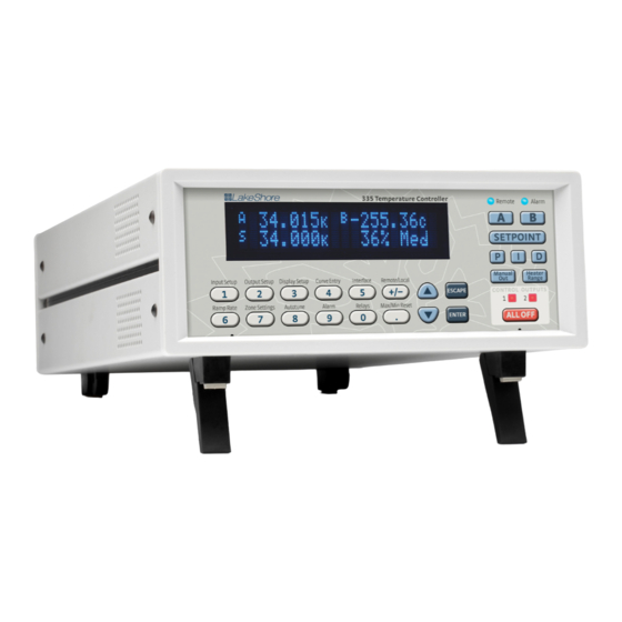
User's Manual
Model 335
Temperature Controller
Lake Shore Cryotronics, Inc.
sales@lakeshore.com
575 McCorkle Blvd.
service@lakeshore.com
Fax: (614) 891-1392
Westerville, Ohio 43082-8888 USA
www.lakeshore.com
Telephone: (614) 891-2243
Methods and apparatus disclosed and described herein have been developed solely on company funds of
Lake Shore Cryotronics, Inc. No government or other contractual support or relationship whatsoever has existed
which in any way affects or mitigates proprietary rights of Lake Shore Cryotronics, Inc. in these developments.
Methods and apparatus disclosed herein may be subject to U.S. Patents existing or applied for.
Lake Shore Cryotronics, Inc. reserves the right to add, improve, modify, or withdraw functions, design modifications,
or products at any time without notice. Lake Shore shall not be liable for errors contained herein or for incidental or
consequential damages in connection with furnishing, performance, or use of this material.
Rev. 1.2
P/N 119-055
04 October 2012
|
www.lakeshore.com
Advertisement
Chapters
Table of Contents
Troubleshooting

Subscribe to Our Youtube Channel
Related Manuals for Lakeshore 335


Summary of Contents for Lakeshore 335
- Page 1 User’s Manual Model 335 Temperature Controller Lake Shore Cryotronics, Inc. sales@lakeshore.com 575 McCorkle Blvd. service@lakeshore.com Fax: (614) 891-1392 Westerville, Ohio 43082-8888 USA www.lakeshore.com Telephone: (614) 891-2243 Methods and apparatus disclosed and described herein have been developed solely on company funds of Lake Shore Cryotronics, Inc.
- Page 2 LIMITED WARRANTY STATEMENT LakeShore undertakes no responsibility that the products will be fit WARRANTY PERIOD: THREE (3) YEARS for any particular purpose for which you may be buying the Products. 1.Lake Shore warrants that products manufactured by Lake Shore (the Any implied warranty is limited in duration to the warranty period.
- Page 3 Technology (NIST); formerly known as the National Bureau of Stan- terms of the Limited Warranty specified above. Any unauthorized dards (NBS). duplication or use of the Model 335 firmware in whole or in part, in print, or in any other storage and retrieval system is forbidden. FIRMWARE LIMITATIONS...
- Page 4 Model 335 Temperature Controller...
- Page 5 RoHS directive. However, in recognition that RoHS compliance is in the best interest of our customers, employees, and the environment, Lake Shore has designed the Model 335 to eliminate the hazardous substances covered in the RoHS directive.
- Page 6 To qualify for the CE Mark, the Model 335 meets or exceeds the requirements of the European EMC Directive 89/335/EEC as a CLASS A product. A Class A product is allowed to radiate more RF than a Class B product and must include the follow- ing warning: WARNING: This is a Class A product.
-
Page 7: Table Of Contents
1.3 Model 335 Specifications ........ - Page 8 3.7.5.3 Connecting to the Model 335 ........
- Page 9 4.7 Locking and Unlocking the Keypad ..........65 www.lakeshore.com...
- Page 10 6.2.4.6 Reading Registers ........... . 94 Model 335 Temperature Controller...
- Page 11 8.9 Calibration Procedure ............. 137 www.lakeshore.com...
- Page 12 8.14.5 Restocking Fee ............145 Model 335 Temperature Controller...
-
Page 13: Product Description
± 10 V analog voltage outputs, alarms, and relays Designed with the user and ease of use in mind, the Model 335 temperature control- ler offers many user-configurable features and advanced functions that until now have been reserved for more expensive, high-end temperature controllers. The... -
Page 14: Sensor Inputs
Model 335 comes standard-equipped with all of the functionality of the controllers it replaces, but offers additional features that save you time and money. With the Model 335, you get a temperature controller you control from the world leader in cryogenic thermometry. -
Page 15: Temperature Control
1.1.2 Temperature Control 1.1.2 Temperature Providing a total of 75 W of heater power, the Model 335 is the most powerful half rack temperature controller available. Designed to deliver very clean heater power, Control precise temperature control is ensured throughout your full scale temperature range for excellent measurement reliability, efficiency and throughput. -
Page 16: Configurable Display
Option measure thermocouple temperature sensors. Calibration for the option is stored on the card so it can be installed in the field and used with multiple Model 335 tempera- ture controllers without recalibration. Model 335 Temperature Controller... -
Page 17: Sensor Selection
Not recommended Chromel-AuFe 0.07% 9006-002 1.2 K to 610 K Not recommended Non-HT version maximum temperature: 325 K Low temperature limited by input resistance range Low temperature specified with self-heating error: " 5 mK TABLE 1-1 Sensor temperature range www.lakeshore.com... - Page 18 Typical sensor sensitivities were taken from representative calibrations for the sensor listed Control stability of the electronics only, in an ideal thermal system Non-HT version maximum temperature: 325 K Accuracy specification does not include errors from room temperature compensation TABLE 1-2 Typical sensor performance Model 335 Temperature Controller...
-
Page 19: Model 335 Specifications
1.3 Model 335 Specifications 1.3 Model 335 Specifications 1.3.1 Input Specifications Sensor Input range Excitation Display Measurement Electronic Measurement temperature Electronic temperature current resolution resolution accuracy coefficient stability coefficient (at 25 °C) Diode Negative 0 V to 2.5 V 10 µA ±0.05% 100 µV... -
Page 20: Sensor Input Configuration
1 to 200% with 1% resolution Manual output 0 to 100% with 0.01% setting resolution Zone control 10 temperature zones with P, I, D, manual heater out, heater range, control channel, ramp rate Setpoint ramping 0.1 K/min to 100 K/min Model 335 Temperature Controller... - Page 21 Settings Input, source, top of scale, bottom of scale or manual Update rate 10/s Range ±10 V Resolution 16-bit, 0.3 mV Accuracy ±2.5 mV Noise 0.3 mV RMS Minimum load resistance 100 ) (short-circuit protected) Connector Detachable terminal block www.lakeshore.com...
-
Page 22: Front Panel
100, 120, 220, 240, VAC, ±10%, 50 or 60 Hz, 210 VA Size 217 mm W × 90 mm H × 317 mm D (8.5 in × 3.5 in × 14.5 in), half rack Weight 7.6 kg (16.8 lb) Approval CE mark Model 335 Temperature Controller... -
Page 23: Safety Summary And Symbols
Lake Shore Cryotronics, Inc. assumes no liability for Cus- tomer failure to comply with these requirements. The Model 335 protects the operator and surrounding area from electric shock or burn, mechanical hazards, excessive temperature, and spread of fire from the instru- ment. - Page 24 Earth (ground) terminal CAUTION or WARNING: See instrument documentation; background color: yellow; Protective conductor terminal symbol and outline: black Frame or chassis terminal On (supply) Off (supply) FIGURE 1-4 Safety symbols Model 335 Temperature Controller...
-
Page 25: General
Another thing to consider when choosing a temperature sensor is that instruments like the Model 335 are not able to read some sensors over their entire temperature range. Lake Shore sells calibrated sensors that operate down to 20 millikelvin (mK), but the Model 335 is limited to above 300 mK in its standard configuration. -
Page 26: Environmental Conditions
Calibrations curve that the Model 335 can understand, and then getting the curve loaded into the instrument. Lake Shore provides a variety of calibration services to fit different accu- racy requirements and budgets. -
Page 27: Precision Calibration
Model 335 user curve loca- tions. You can use it to read curves from the Model 335 and save them to files. A CD is provided with Lake Shore calibrated sensors that contains all the proper formats to load curves using the Curve Handler™... -
Page 28: Sensor Installation
Windows® PC. This version works with the IEEE-488 and USB computer interfaces on the Model 335, and allows the temperature curves to be manipulated directly in the program window. This version will also work with all existing Lake Shore temperature controller and temperature monitor instruments. -
Page 29: Contact Area
Thin wire insulation is preferred, and twisted wire should be used to reduce the effect of RF noise if it is present. The wire used on the room temperature side of the vacuum boundary is not critical, so copper cable is normally used. www.lakeshore.com... -
Page 30: Lead Soldering
They can also be wound onto a bobbin that is firmly attached to the cold surface. Some sensor packages include a thermal anchor bobbin and wrapped lead wires to simplify thermal anchoring. Model 335 Temperature Controller... -
Page 31: Thermal Radiation
2.5.1 Heater Resistance Cryogenic cooling systems have a wide range of cooling power. The resistive heater must be able to provide sufficient heating power to warm the system. The Model 335 and Power can provide up to 75 W of power from Output 1, up to 25 W of power from Output 2 in current mode, and up to 1 W of power from Output 2 in voltage mode. -
Page 32: Heater Location
It is possible to choose a heater value that results in a maximum power greater than the power rating for either current source output, but doing so can cause the Model 335 to work improperly. In this situation the max user current setting should be used to limit the power. -
Page 33: Heater Wiring
If both control stability and measurement accuracy are critical it may be necessary to use two sensors, one for each function. Many tempera- ture controllers including the Model 335 have multiple sensor inputs for this reason. www.lakeshore.com... -
Page 34: Thermal Mass
2.7 PID Control For closed-loop operation, the Model 335 temperature controller uses an algorithm called PID control. The control equation for the PID algorithm has three variable terms: proportional (P), integral (I), and derivative (D). See FIGURE 2-2. Changing these variables for best control of a system is called tuning. -
Page 35: Proportional (P)
I-setting when used. 2.7.4 Manual Output The Model 335 has a control setting that is not a normal part of a PID control loop. Manual Output can be used for open loop control, meaning feedback is ignored and the heater output stays at the user’s manual setting. - Page 36 2: Cooling System Design and Temperature Control HAPTER FIGURE 2-2 Examples of PID control Model 335 Temperature Controller...
-
Page 37: Manual Tuning
Lower heater ranges are normally needed for lower temperature. The Model 335 is of no use controlling at or below the temperature reached when the heater was off. Many systems can be tuned to control within a degree or two above that temperature. -
Page 38: Tuning Integral
2. Use the oscillation period of the load that was measured in section 2.8.2 in sec- onds. Divide 1000 by the oscillation period to get the integral setting. 3. Enter the integral setting into the Model 335 and watch the load temperature approach the setpoint. -
Page 39: Tuning Derivative
D. Autotune works only with one control loop at a time and does not set the man- ual output or heater range. Setting an inappropriate heater range is potentially dan- gerous to some loads, so the Model 335 does not automate that step of the tuning process. -
Page 40: Zone Tuning
The parameters are then entered into the Model 335 where up to ten zones can be defined with different P, I, D, heater range, manual output, ramp rate, and control input settings. An upper boundary setting is assigned as the maximum temperature for that zone. -
Page 41: General
Instruments themselves may be shipped as several parts. The items included with the Model 335 are listed below. Contact Lake Shore immediately if there is a shortage of parts or accessories. Lake Shore is not responsible for any miss- ing items if they have not been notified within 60 days of shipment. -
Page 42: Rear Panel Definition
FIGURE 3-2 Line input assembly 3.4.1 Line Voltage The Model 335 has four different AC line voltage configurations so that it can be oper- ated from line power anywhere in the world. The nominal voltage and voltage range of each configuration is shown below. (The recommended setting for 230 V operation is 240 V.) -
Page 43: Line Fuse And Fuse Holder
3.4.2 Line Fuse and The line fuse is an important safety feature of the Model 335. If a fuse ever fails, it is important to replace it with the value and type indicated on the rear panel for the line Fuse Holder voltage setting. -
Page 44: Sensor Lead Cable
A shield is most effective when it is near the measurement potential so the Model 335 offers a shield at measurement common. The shield of the sensor cable should be connected to the shield pin of the input connector. The shields should not be connected to earth ground on the instrument chassis. -
Page 45: Sensor Polarity
When 2-lead sensors are used in 4-lead measurements, the short leads on the sensor have an insignificant resistance. Resistive sensor Diode (option only) – – – – FIGURE 3-5 4-lead measurement www.lakeshore.com... -
Page 46: Two-Lead Sensor Measurement
Run different inputs and outputs in their own shielded cable Use twisted wire inside the cooling system Use twisted wire for heater leads Use a grounded receptacle for the instrument power cord Consider ground strapping the instrument chassis to other instruments or computers Model 335 Temperature Controller... -
Page 47: Thermocouple Sensor Inputs (Thermocouple Model 3060)
3.6 Thermocouple Sensor Inputs (Thermocouple Model 3060) 3.6 Thermocouple The information in this section is for a Model 335 configured with thermocouple sen- sor inputs. Thermocouple inputs are not installed on the standard Model 335, but can Sensor Inputs be added by purchasing the Model 3060 dual thermocouple input option. Refer to (Thermocouple section 8.12 for installation of the Model 3060. -
Page 48: Heater Output Setup
Wire manufacturers recommend 26 AWG or larger wire to carry 1.732 A of current, but there is little advantage in using wire smaller than 20 AWG to 22 AWG outside the cryostat. Inside the cryostat, smaller gauge wire is often desirable. Model 335 Temperature Controller... -
Page 49: Heater Output Noise
Also avoid connecting heater leads to sensor leads or any other instrument inputs or outputs. 3.7.4 Heater Output The heater output circuitry in the Model 335 is capable of sourcing 75 W of power. This type of circuitry can generate some electrical noise. The Model 335 was designed Noise... -
Page 50: Power Supply Setup
Some power supplies can be damaged if there is a programming voltage present at their input when they are turned off. This can happen if the Model 335 and power supply use a different source of line power or are turned on and off individ- ually. -
Page 51: Programming Voltages Under 10 V
= 10 V × R1/(R1+R2). It is also important to keep the sum of R1 + R2 > 1000 ) or the Model 335 output may not reach the output voltage setting due to internal overload protection. For a programming input range of 0 V to5 V, rec- ommended values are: R1 = R2 = 2000 ). - Page 52 3: Installation HAPTER Model 335 Temperature Controller...
-
Page 53: General
Chapter 4: Operation 4.1 General This chapter provides instructions for the general operating features of the Model 335 temperature controller. Advanced operation is in Chapter 5. Computer interface instructions are in Chapter 6. FIGURE 4-1 Model 335 front panel 4.1.1 Understanding This section is intended to be a quick guide through the necessary key presses to arrive at and set the desired features. -
Page 54: Front Panel Description
Model 335. The number pad keys are dual function keys. If the instrument is in the number entry mode, the keys are used to enter numbers. If it is in normal operating mode, the number keys provide menu entry points. -
Page 55: Annunciators
Enter to accept the new data. Press Escape once to clear the entry, and press it twice to return to the Menu Navigation mode. www.lakeshore.com... -
Page 56: Display Setup
Model 335, which simultaneously displays up to four readings. 4.3.1 Display Modes The Model 335 provides four display modes designed to accommodate different instrument configurations and user preferences. The display modes are listed here, and further information is provided for each display in section 4.3.1.1 to section 4.3.1.4. -
Page 57: Two Loop Mode
If the sensor input is not assigned as the Control Input of any control loop, then the bottom line is blank. If the control loop that uses the sensor input is in Open Loop mode, then a heater percentage is shown instead of a setpoint. www.lakeshore.com... -
Page 58: Custom Display Mode
Output 1 or Output 2: this option displays the output number, followed by the heater output percentage, and the heater range of the specified output. FIGURE 4-6 Custom display modes Menu Navigation: Display SetupQDisplay Mode (Custom) Interface Command: DISPLAY Model 335 Temperature Controller... -
Page 59: Display Brightness
Interface Command: BRIGT 4.4 Input Setup The Model 335 supports a variety of temperature sensors manufactured by Lake Shore and other manufacturers. An appropriate sensor type must be selected for each input. If the exact sensor model is not shown, use the sensor input performance chart in TABLE 4-6 to choose an input type with similar range and excitation. -
Page 60: Diode Sensor Input Setup
4.4.2 Positive PTC resistor sensors include the platinum and rhodium-iron sensors detailed in TABLE 4-6. More detailed specifications are provided in TABLE 1-2. The Model 335 Temperature supplies a 1 mA excitation current for the PTC resistor sensor type. A resistance range Coefficient (PTC) selection is available in order to achieve better reading resolution. -
Page 61: Range Selection
EMF voltages can be an appreciable part of a low voltage sensor measurement. The Model 335 can help with a thermal compensation algorithm. The instrument will automatically reverse the polarity of the current source every other reading. The average of the positive and negative sensor readings will cancel the thermal EMF voltage that is present in the same polarity, regardless of current direction. -
Page 62: Thermocouple Sensor Input Setup (Model 3060 Only)
Input SetupQInput (A, or B) QCurrent Reversal (Off or On) Default: On Interface Command: INTYPE When a Model 3060 thermocouple option is installed in the Model 335, a thermocou- 4.4.6 Thermocouple ple option becomes available under the Sensor Type parameter in the Input Setup Sensor Input Setup menu. -
Page 63: Curve Selection
The Model 335 supports a variety of temperature sensors manufactured by Lake Shore and other manufacturers. After the appropriate sensor type is selected (section 2.2), an appropriate curve may be selected. The Model 335 can use curves from several sources. Standard curves are preloaded with every instrument, and they are numbered 1 to 20. -
Page 64: Filter
45 readings, or 4.5 s. The time constant (time it takes to settle to within 36.8% of the step value after a step change) for a given number of filter points can be derived using the following formula: Model 335 Temperature Controller... -
Page 65: Input Name
Interface: FILTER 4.4.9 Input Name To increase usability and reduce confusion, the Model 335 provides a means of assigning a name to each sensor input. The designated input name is displayed on the front panel when the A or B keys are pressed, identifying the respective sensor. The input name can also be configured to be displayed when using the custom display mode. -
Page 66: Preferred Units
The power ranges for each output provide decade steps in power. Menu Navigation: Output SetupQOutput (1 or 2) Default: Current Interface: HTRSET Model 335 Temperature Controller... -
Page 67: Heater Output Type (Output 2)
Interface: HTRSET 4.5.1.3 Max Current and Heater Resistance The Model 335 heater outputs are designed to work optimally into a 25 ) or 50 ) heater. The Heater Resistance and Max Current parameters work together to limit the maximum available power into the heater. This is useful for preventing heater dam- age or limiting the maximum heater power into the system. -
Page 68: User Max Current
Example 1: A 50 ), 30 W heater is connected to Output 1. Power lLimit Voltage compliance limit I = Squrt(P/R) I = V/R I = Squrt(30 W/50 )) I = 50 V/50 ) I = 0.77 A I = 1 A Model 335 Temperature Controller... -
Page 69: Power Up Enable
Interface: HTRSET 4.5.1.4 Power Up Enable All configuration parameters of the Model 335 can be retained through a power cycle. Some systems require that the heater range is turned off when power is restored. The power up enable feature allows the user to choose whether or not the heater range is turned off each time the instrument power is cycled. -
Page 70: Heater Out Display
The Closed Loop PID mode is the most commonly used closed loop control mode for tightly controlling temperature using the heater outputs of the Model 335. In this mode the controller attempts to keep the load exactly at the setpoint temperature you entered. -
Page 71: Open Loop Mode
A control loop consists of a control output for controlling the temperature, and an input for feedback into the control algorithm. Use the Control Input parame- ter to assign the control input sensor to the desired output. www.lakeshore.com... -
Page 72: Proportional (P)
Refer to section 4.3 for details on configuring the front panel display. Menu Navigation: IQ(0 to 1000) Default: 20 Interface Command: PID Model 335 Temperature Controller... -
Page 73: Derivative (D)
1/i the integral time in seconds, if used at all. As a convenience to the operator, the Model 335 derivative time constant is expressed in percent of ¼ the integral time. The range is between 0% and 200%. Start with settings of 0%, 50%, or 100%, and determine which setting gives you the type of control you desire. -
Page 74: Setpoint
For these applications, the Model 335 can control temperature in sensor units. To control in sensor units, set the Preferred Units parameter to sensor. When controlling in sensor units, the Setpoint resolution matches the display resolution for the sensor input type given in the speci- fications (section 1.3). -
Page 75: Setpoint Ramping
4.5.1 Heater Outputs 4.5.1.7.7 Setpoint Ramping The Model 335 can generate a smooth setpoint ramp when the setpoint units are expressed in temperature. You can set a ramp rate in degrees per minute with a range of 0 to 100 and a resolution of 0.1. Once the ramping feature is turned on, its action is initiated by a setpoint change. -
Page 76: Heater Range
The Monitor Out mode uses the output to provide a voltage proportional to an input sensor reading to be used by an external device such as a data logger. Model 335 Temperature Controller... -
Page 77: Warm Up Supply
Chapter 6 for details on computer interface operation. 4.6.2.1 Remote/Local Local refers to operating the Model 335 from the front panel. Remote refers to oper- ating the controller via the IEEE 488 Interface. The keypad is disabled during remote operation, except for the Remote/Local key and the ALL OFF key. - Page 78 To unlock the keypad, press and hold Enter for 5 s. Use the numeric keypad to enter the three-digit lock code. If the lock code is accepted, *** Keypad Unlocked *** will be displayed for 3 s and the display will return to normal. All Model 335 parameters are now accessible.
-
Page 79: General
5.1 General Chapter 5: Advanced Operation 5.1 General This chapter provides information on the advanced operation of the Model 335 tem- perature controller. 5.2 Autotune The Model 335 can automate the tuning process of typical cryogenic systems with the Autotune feature. For additional information about the algorithm refer to section 2.9. - Page 80 PI and PID Autotuning tem to Autotune heater range control parameters TABLE 5-1 Autotune stages Menu Navigation: AutotuneQInput (A, B)Q(Autotune P, Autotune PI, Autotune PID) Interface Command: ATUNE Model 335 Temperature Controller...
-
Page 81: Zone Settings
5.3 Zone Settings 5.3 Zone Settings The Model 335 allows you to establish up to ten custom contiguous temperature zones where the controller will automatically use pre-programmed values for PID, heater range, manual output, ramp rate, and control input. Zone control can be active for both control loops at the same time. - Page 82 Upper boundary: Proportional Integral Derivative MHP Output Heater Range Ramp Rate Control Input A Off A Med A Default (0.1–1000) (0.1–1000) (0–200) (0–100%) (0.1–100 K/min) Zone 01 A Low A High FIGURE 5-2 Record of zone settings Model 335 Temperature Controller...
-
Page 83: Bipolar Control
For these types of bipolar devices, the Model 335 features a bipolar control mode. In this mode, the Model 335 is configured to drive these devices to control temperature using Output 2 in Voltage mode. -
Page 84: Warm Up Percentage
Heater Range setting, and by design is always enabled. Menu Navigation: Output SetupQOutput 2 QOutput Type (Voltage)QOutput Mode (Monitor Out)Q Control Input (None, Input A, Input B) Default: Control InputQNone Interface Command: OUTMODE Model 335 Temperature Controller... -
Page 85: Monitor Units
Control Input (None, Input A, Input B)QMonitor Out Units (Kelvin, Celsius, or Sensor) QPolarity (Unipolar or Bipolar) ENTER Output SetupQOutput 2 QMonitor Out (Unipolar) or -10 V (Bipolar)Q(See note below) +10 V Output SetupQ Output 2 QMonitor Out Q(See note below) www.lakeshore.com... -
Page 86: Alarms And Relays
The two relays on the Model 335 can also be tied to alarm functions as described in section 5.7.2. You may want to set the Visible parameter to Off if there is no need for showing the alarm state on the front panel, for instance, if you are using the alarm function to trigger a relay. -
Page 87: Alarm Latching
AlarmQInput (A, B)QAlarm (On) QLatching (Off, On) ENTER AlarmQInput (A, B)QAlarm (On) QDeadband (see note below) ENTER Low and High Setpoint limits are determined by the Preferred Units of the associated sensor input. Default: LatchingQOff DeadbandQ1.0000 K Interface Command: ALARM www.lakeshore.com... -
Page 88: Relays
HAPTER 5.7.2 Relays There are two relays on the Model 335 numbered 1 and 2. They are most commonly thought of as alarm relays, but they may be manually controlled also. Relay assign- ments are configurable as shown in FIGURE 5-7. Two relays can be used with one sen- sor input for independent high and low operation, or each can be assigned to a different input. -
Page 89: Curve Numbers And Storage
5.8 Curve Numbers and Storage 5.8 Curve The Model 335 has 20 standard curve locations, numbered 1 through 20. At present, not all locations are occupied by curves; the others are reserved for future updates. If Numbers and a standard curve location is in use, the curve can be viewed using the view operation. -
Page 90: Front Panel Curve Entry Operations
The breakpoints should be entered with the sensor units value increasing as point number increases. There should not be any breakpoint locations left blank in the mid- dle of a curve. The search routine in the Model 335 interprets a blank breakpoint as the end of the curve. -
Page 91: Edit A Breakpoint Pair
FIGURE 5-8 Left: Scroll to highlight a breakpoint number; Middle: Press the enter key to highlight the sensor value of the selected pair ; Right: Press the enter key again, and the temperature value is highlighted Menu Navigation: Curve Entry QEdit (21–59) QCurve Points (1–200) ENTER Interface Command: CRVPT www.lakeshore.com... -
Page 92: Add A New Breakpoint Pair
To convert curves published in Celsius to kelvin, add 273.15 to the temperature in Celsius. The input voltage of the Model 335 is limited to ±50 mV, so any part of the curve that extends beyond ±50 mV is not usable by the instrument. -
Page 93: Erase Curve
Both DT-400 Series and platinum SoftCal™ algorithms require a standard curve that is already present in the Model 335. When you enter the type of sensor being cali- brated, select the correct standard curve. When calibration is complete, assign the new curve to an input. -
Page 94: Softcal™ With Silicon Diode Sensors
Lake Shore for best accuracy. The calibration points can be entered into the Model 335 so it can generate a curve. If the CalCurve™ service is purchased with the calibrated sensor, the curve is also generated at the factory and can be entered like any other curve. -
Page 95: Softcal™ Accuracy With Dt-400 Series Silicon Diode Sensors
If you are using two points, the algorithm has enough information to tilt the curve, achieving good accuracy between the data points. The third point extends the improved accuracy to span all three points. www.lakeshore.com... -
Page 96: Softcal™ Accuracy With Platinum Sensors
7. To cancel the operation, either choose No to the Generate SoftCal prompt, or press Escape. The Generate Softcal operation will overwrite an existing user curve. Please ensure the curve number you are writing to is correct before generating the calibrated curve. Model 335 Temperature Controller... -
Page 97: Emulation Modes
5.11.1 Emulation Mode To assist in the ease of replacing a Model 331 or a Model 332 with a Model 335, cer- tain hardware settings are automatically configured when the Emulation mode is set Configuration to Model 331 or Model 332. -
Page 98: Unsupported Commands
Model 335 setting, for full compatibility with the Model 331 or the Model 332. Some settings will not directly apply to the Model 335, such as the Auto- tune control modes. Attempts to set an inapplicable setting will be ignored. -
Page 99: Hardware Differences
100 ) heater. The Model 332 provides a ±10 V voltage source output with 1 A maxi- mum current, providing up to 10 W into a 10 ) heater. The Model 335 provides both a ±10 V voltage source with 100 mA maximum current, which is the exact same hard-... - Page 100 5: Advanced Operation HAPTER Model 335 Temperature Controller...
-
Page 101: General
Cable lengths are limited to 2 m (6.6 ft) for each device and 20 m (65.6 ft) for the entire bus. The Model 335 can drive a bus with up to ten loads. If more instruments or cable length is required, a bus expander must be used. -
Page 102: Changing Ieee-488 Interface Parameters
LLO (Local Lockout): prevents the use of instrument front panel controls DCL (Device Clear): clears Model 335 interface activity and puts it into a bus idle state Finally, addressed bus control commands are multiline commands that must include the Model 335 listen address before the instrument responds. -
Page 103: Common Commands
Most device specific com- mands also work if performed from the front panel. Model 335 device specific com- mands are detailed in section 6.4.1 and summarized in TABLE 6-6. -
Page 104: Status System Overview
6: Computer Interface Operation HAPTER 6.2.4 Status System The Model 335 implements a status system compliant to the IEEE-488.2 standard. The status system provides a method of recording and reporting instrument informa- Overview tion and is typically used to control the Service Request (SRQ) interrupt line. A dia- gram of the status system is shown in FIGURE 6-1. - Page 105 CAL = Calibration error ATUNE = Autotune process completed NRDG = New sensor reading RAMP1 = Loop 1 ramp done RAMP2 = Loop 2 ramp done OVLD = Sensor overload ALARM = Sensor alarming FIGURE 6-1 Model 335 status system www.lakeshore.com...
-
Page 106: Status Byte Register
To program an enable register, send a decimal value that corresponds to the desired binary-weighted sum of all bits in the register (TABLE 6-2). The actual commands are described throughout (section 6.4.1). Model 335 Temperature Controller... -
Page 107: Clearing Registers
TABLE 6-3 Register clear methods 6.2.5 Status System As shown in FIGURE 6-1, there are two register sets in the status system of the Model 335: Standard Event Status Register and Operation Event Register. Detail: Status Register Sets 6.2.5.1 Standard Event Status Register Set... -
Page 108: Operation Event Register Set
Sensor Overload (OVLD), Bit (1): this bit is set when a sensor reading is in the over- load condition Alarming (ALARM), Bit (0): this bit is set when an input is in an alarming state, and the Alarm Visible parameter is on Model 335 Temperature Controller... -
Page 109: Status System Detail: Status Byte Register And Service Request
MSS function. A *STB? will read the status of the MSS bit (along with all of the summary bits), but also will not clear it. To clear the MSS bit, either clear the event register that set the summary bit or disable the summary bit in the Service Request Enable Register. www.lakeshore.com... -
Page 110: Service Request Enable Register
The serial poll does not clear MSS. The MSS bit stays set until all enabled Status Byte summary bits are cleared, typically by a query of the associated event register (section 6.2.6.4). The programming example in TABLE 6-4 initiates an SRQ when a command error is detected by the instrument. Model 335 Temperature Controller... -
Page 111: Using Status Byte Query (*Stb?)
The bus controller can, for example, send a query command to the Model 335 and then wait for MAV to set. If the MAV bit has been enabled to initiate an SRQ, the user's program can direct the bus controller to look for the SRQ leaving the bus available for other use. -
Page 112: Usb Interface
USB peripheral devices, and it allows the common USB A-type to Connection B-type cable to be used to connect the Model 335 to a host PC. The pin assignments for A-type and B-type connectors are shown in section 8.10. The maximum length of a USB cable, as defined by the USB 2.0 standard, is 5 m (16.4 ft). -
Page 113: Installing The Driver From Windows® Update In Windows® Xp
If the Found New Hardware wizard is unable to connect to Windows® Update or find the drivers, a message to “Insert the disc that came with your Lake Shore Model 335” will be displayed. Click Cancel and refer to section 6.3.3.3 to install the driver from the web. -
Page 114: Manually Install The Driver
Lake Shore Model 335 should appear indented underneath Other Devices. If it is not displayed as Lake Shore Model 335, it might be displayed as USB Device. If neither are displayed, click Action and then Scan for hardware changes, which may open the Found New Hardware wizard automatically. -
Page 115: Installing The Usb Driver From The Included Cd
+ icon. Lake Shore Model 335 should appear indented underneath Ports (COM & LPT). If it is not displayed as Lake Shore Model 335, it might be displayed as USB Device. If neither are displayed, click Action and then select Scan for hardware changes, which may open the Found New Hardware wizard automatically. -
Page 116: Communication
A special ASCII character, line feed (LF 0AH), is used to indicate the end of a mes- sage string. This is called the message terminator. The Model 335 will accept either the line feed character alone, or a carriage return (CR 0DH) followed by a line feed as the message terminator. -
Page 117: Command Summary
Form of the query input Input Curve Number Query INCRV? <input>[term] Input: Syntax of user parameter input* Format: see key below <input> Specify input: A–B Definition of returned parameter Returned: <curve number>[term] Format: Syntax of returned parameter FIGURE 6-6 Sample query format www.lakeshore.com... -
Page 118: Command Function
Warmup Supply Parameter Query IEEE? IEEE-488 Interface Parameter Query ZONE Control Loop Zone Table Parameter Cmd INCRV Input Curve Number Cmd ZONE? Output Zone Table Parameter Query INCRV? Input Curve Number Query TABLE 6-6 Command summary Model 335 Temperature Controller... -
Page 119: Interface Commands
To enable event flags 0, 4, and 7, send the command ESE 145[term]. 145 is the sum Example of the bit weighting for each bit. Bit Weighting Event Name Total: ESE? Event Status Enable Register Query ESE?[term] Input Returned <bit weighting>[term] Format nnn (Refer to section 6.2.5 for a list of event flags) www.lakeshore.com... -
Page 120: Esr? Standard Event Status Register Query
Places a 1 in the controller output queue upon completion of all pending selected device operations. Send as the last command in a command string. Not the same as OPC. RST Reset Instrument Command RST[term] Input Remarks Sets controller parameters to power-up settings. Model 335 Temperature Controller... -
Page 121: Sre Service Request Enable Register Cmd
Returned <status>[term] Format <status> 0 = no errors found, 1 = errors found Remarks The Model 335 reports status based on the test done at power up. WAI Wait-to-Continue Command WAI[term] Input Remarks Causes the IEEE-488 interface to hold off until all pending operations have been com- pleted. -
Page 122: Alarm
<high state> 0 = Off, 1 = On <low state> 0 = Off, 1 = On ALMRST Reset Alarm Status Command Input ALMRST[term] Remarks Clears both the high and low status of all alarms, including latching alarms. Model 335 Temperature Controller... -
Page 123: Analog
Autotune process will not be performed. The TUNEST? query can be used to check if an Autotune error occurred. BRIGT Display Brightness Command Input BRIGT <brightness value>[term] Format <brightness value> 0–3 Remarks Sets the display brightness for the front panel display 0=25%, 1=50%, 2=75%, 3=100%. www.lakeshore.com... -
Page 124: Brigt? Display Brightness Query
DT-470, serial number of 00011134, data format of volts versus kelvin, upper temperature limit of 325 K, and negative coefficient. CRVHDR? Curve Header Query Input CRVHDR? <curve>[term] Format <curve> Valid entries: 1–59. Returned <name>,<SN>,<format>,<limit value>,<coefficient>[term] Format s[15],s[10],n,+nnn.nnn,n (refer to command for description) Model 335 Temperature Controller... -
Page 125: Crvpt
The 10 µA excitation current is the only calibrated excitation current, and is used in almost all applications. Therefore the Model 335 will default the 10 µA current set- ting any time the input sensor type is changed in order to prevent an accidental change. -
Page 126: Dispfld
Loop A, 3=Input B, 4=Input B Max/Min, 5=Two Input, Loop B, 6=Custom, 7=Two Loop Remarks When the input display mode is set to Custom, use the DISPFLD command to configure the display. DISPLAY? Display Setup Query Input DISPLAY?[term] Returned <mode>[term] Format n (refer to command for description) Model 335 Temperature Controller... -
Page 127: Emul
(Sensor) Remarks The 331 and 332 emulation modes provide a means of using the Model 335 in place of a Model 331 or 332 in a software controlled system without updating the software. The emulation mode setting only affects remote operation; front panel operation of the Model 335 is not changed. -
Page 128: Htrset
IEEE IEEE-488 Interface Parameter Command Input IEEE <address>[term] Format <address> Specifies the IEEE address: 1–30. (Address 0 and 31 are reserved.) Example IEEE 4[term] after receipt of the current terminator, the instrument responds to address 4. Model 335 Temperature Controller... -
Page 129: Ieee? Ieee-488 Interface Parameter Query
INNAME? Sensor Input Name Query Input INNAME? <input>[term] Format <input> Specifies input to query: A or B. Returned <name>[term] Format s[15] (refer to command for description) www.lakeshore.com... -
Page 130: Intype
INTYPE? <input>[term] Format <input> Specifies input to query: A or B. Returned <sensor type>,<autorange>,<range>,<compensation>,<units> [term] Format n,n,n,n,n (refer to command for description) Remarks If autorange is on, the returned range parameter is the currently auto-selected range. Model 335 Temperature Controller... -
Page 131: Krdg? Kelvin Reading Query
Specifies which input to query: A or B. Returned <min value>,<max value>[term] Format ±nnnnnn,±nnnnnn Remarks Returns the minimum and maximum input data. Also see the RDGST? query. MNMXRST Minimum and Maximum Function Reset Command Input MNMXRST[term] Remarks Resets the minimum and maximum data for all inputs. www.lakeshore.com... -
Page 132: Mode
Remote Interface Mode Command Input MODE <mode>[term] Format <mode> 0 = local, 1 = remote, 2 = remote with local lockout. Example MODE 2[term] places the Model 335 into remote mode with local lockout. MODE? Remote Interface Mode Query Input MODE?[term] Returned <mode>[term]... -
Page 133: Opstr?
PID 1,10,50,0[term] Output 1 P is 10, I is 50, and D is 0%. PID? Control Loop PID Values Query Input PID? <output>[term] Format <output> Specifies which output’s control loop to query: 1 or 2. Returned <P value>,<I value>,<D value>[term] Format +nnnnn,+nnnnn,+nnnn (refer to command for description) www.lakeshore.com... -
Page 134: Polarity Output Voltage Polarity Command
RAMPST? Control Setpoint Ramp Status Query Input RAMPST? <output>[term] Format <output> Specifies which output’s control loop to query: 1 or 2. Returned <ramp status>[term] Format <ramp status> 0 = Not ramping, 1 = Setpoint is ramping. Model 335 Temperature Controller... -
Page 135: Range
RELAY 1,2,B,0[term] relay 1 activates when Input B low alarm activates. RELAY? Relay Control Parameter Query Input RELAY? <relay number>[term] Format <relay number> Specifies which relay to query: 1 or 2. Returned <mode>,<input alarm>,<alarm type>[term] Format n,a,n (refer to command for description) www.lakeshore.com... -
Page 136: Relayst? Relay Status Query
SETP? Control Setpoint Query Input SETP? <output>[term] Format <output> Specifies which output to query: 1 or 2. Returned <value>[term] Format ±nnnnnn (refer to command for description) Model 335 Temperature Controller... -
Page 137: Srdg? Sensor Units Input Reading Query
Remarks If initial conditions are not met when starting the autotune procedure, causing the autotuning process to never actually begin, then the error status will be set to 1 and the stage status will be stage 00. www.lakeshore.com... -
Page 138: Warmup
Specifies which heater output to query: 1 or 2. <zone> Specifies which zone in the table to query. Valid entries: 1–10. Returned < upper boundary>,<P value>,<I value>,<D value>,<mout value>,<range>,<input>,<rate>[term] Format +nnnnn,+nnnnn,+nnnnn,+nnnn, +nnnnn,n,n, +nnnn (refer to command for description) Model 335 Temperature Controller... -
Page 139: General
Approximately 6 m (20 ft) long. Refer to FIGURE 7-1. Heater output conditioner. The heater output conditioner is a passive filter that further 3003 reduces the already low heater output noise of the Model 335. Refer to section 7.7 and see FIGURE 7-3. 6201†... - Page 140 Half-rack mounting kit for one Model 335 temperature controller. Half-length mounting panel RM-½ and mounting ears to attach one Model 335 to a 483 mm (19 in) rack mount space. See FIGURE 7-2. Dual mounting shelf for two Model 335 temperature controllers. Mounting shelf to attach any RM-2 two 5.25 in tall half-rack instruments side-by-side on a 483 mm (19 in) rack mount shelf.
-
Page 141: Rack Mounting
(red) shield FIGURE 7-1 Model 335 sensor and heater cable assembly 10 ft: P/N 112-177, 20 ft: P/N 112-178 7.5 Rack Mounting The Model 335 can be installed into a 483 mm (19 in) rack mount cabinet using the optional Lake Shore Model RM-½... -
Page 142: Model 3060-H Thermocouple Input Option
Input Option used to measure thermocouple temperature sensors. Calibration for the option is stored on the card so it can be installed in the field and used with multiple Model 335 temperature controllers without recalibration. Model 335 Temperature Controller... -
Page 143: Model 3003 Heater And Output Conditioner
7.7 Model 3003 The Lake Shore Model 3003 heater output conditioner is a passive filter that reduces the already low noise present in the heater output of the Model 335. The Model 3003 Heater and Output connects between the heater output terminals on the rear panel of a controller and a Conditioner resistive heater. - Page 144 7: Options and Accessories HAPTER Model 335 Temperature Controller...
-
Page 145: General
Lockups not being overloaded. 3. Ensure that the USB cable is not unplugged and that the Model 335 is not pow- ered down while the com port is open. The USB driver creates a com port when the USB connection is detected, and removes the com port when the USB connec- tion is no longer detected. -
Page 146: Ieee Interface Troubleshooting
8.4 Fuse Drawer The fuse drawer supplied with the Model 335 holds the instrument line fuses and line voltage selection module. The drawer holds two 5 mm × 20 mm (0.2 in × .79 in) time delay fuses. -
Page 147: Fuse Replacement
100/120/220/240 V; 3.15 A T 250 V; 5 × 20 mm. 6. Re-assemble the line input assembly in reverse order. 7. Verify that the voltage indicator is in the line input assembly window. 8. Connect the instrument power cord. 9. Turn the power switch On (l). www.lakeshore.com... -
Page 148: Factory Reset Menu
Input B Range Location 2 units Kelvin Ramp rate 0.100 K/min Location 3 source Setpoint 1 Control input Default Location 3 units Kelvin Location 4 source Output 1 Location 4 units Kelvin Brightness TABLE 8-1 Default values Model 335 Temperature Controller... -
Page 149: Product Information
The calibration memory is either corrupt, or is at the default, uncalibrated state. This **Invalid Cal** message appears when the Model 335 is first powered on. To clear the message, and Press Escape & Enter continue with instrument start-up, press Escape and Enter simultaneously. -
Page 150: Rear Panel Connector Definition
FIGURE 3-7. Definition FIGURE 8-3 Sensor input A and B Symbol Description I– –Current V– –Voltage None Shield +Voltage +Current None Shield TABLE 8-3 Sensor input A and B connector details FIGURE 8-4 Heater output connectors Model 335 Temperature Controller... - Page 151 Relay 2 normally closed Relay 2 common Relay 2 normally open TABLE 8-4 Terminal block pin and connector details FIGURE 8-6 USB pin and connector details Name Description +5 VDC Data – Data + Ground TABLE 8-5 USB pin and connector details www.lakeshore.com...
-
Page 152: Ieee-488 Interface Connector
The total length of cable allowed in a system is 2 m for each device on the bus, or 20 m maximum. The Model 335 can drive a bus of up to 10 devices. A connector extender is required to use the IEEE-488 interface and relay terminal block at the same time. -
Page 153: Electrostatic Discharge
The Model 3060 option card is field installable; however, do not attempt to service other parts of the instrument as they are not user-serviceable. Failure to comply could result in injury or death to the operator. www.lakeshore.com... - Page 154 Follow ESD procedures in section 8.11 to avoid inducing an electrostatic discharge (ESD) into the device. 1. Turn the Model 335 power switch Off. Unplug the power cord from the wall out- let, then the instrument. 2. Stand the unit on its face. Use the hex driver to remove the four screws on both sides of the top cover;...
-
Page 155: Firmware Updates
Firmware this procedure. 1. Go to http://www.lakeshore.com/products/cryogenic-temperature-controllers/ model-335/Pages/Overview.aspx to download the instrument firmware. 2. Enter your name and email address so that we can keep you updated on any new firmware for your instrument. 3. Click the “Go to the download” bar and follow the prompts that are provided on the screen for you. -
Page 156: Technical Inquiries
Contact Lake Shore Service through any of the means listed below. However, the most direct and efficient means of contacting is to complete the online service request form at http://www.lakeshore.com/sup/serf.html. Provide a detailed description of the problem and the required contact information. You will receive a response within 24 hours or the next business day in the event of weekends or holidays. -
Page 157: Shipping Charges
Lake Shore. Equipment serviced Charges out-of-warranty will be returned FOB Lake Shore. 8.14.5 Restocking Fee Lake Shore reserves the right to charge a restocking fee for items returned for exchange or reimbursement. www.lakeshore.com... - Page 158 8: Service HAPTER Model 335 Temperature Controller...
- Page 159 To convert Celsius to Fahrenheit: multiply °C by 1.8 then add 32, or: °F = (1.8 × °C) + 32 To convert Fahrenheit to kelvin, first convert °F to °C, then add 273.15. To convert Celsius to kelvin, add 273.15. www.lakeshore.com...
- Page 160 20.33 -6.48 266.67 -309.67 -189.82 83.33 -140 -95.96 177.59 26.33 -3.15 -300 -184.44 88.71 -139.67 -95.37 177.78 -1.11 272.04 -299.67 -184.26 88.89 -135.67 -93.15 30.33 -0.93 272.22 -297.67 -183.15 -130 183.15 273.15 TABLE A-1 Temperature conversions Model 335 Temperature Controller...
- Page 161 Use of liquid helium (LHe) and liquid nitrogen (LN ) is often associated with the Model 335 temperature controller. Although not explosive, there are a number of safety considerations to keep in mind in the handling of LHe and LN B.2 Properties...
- Page 162 15 minutes. In case of massive exposure, remove clothing while showering with warm water. The patient should not drink alcohol or smoke. Keep warm and rest. Call a physician immediately. Model 335 Temperature Controller...
- Page 163 Appendix C: Curve Tables C.1 General Standard curve tables included in the Model 335 temperature controller are as follows: Curve Location Model Table Curve 01 DT-470 Silicon Diode Table D-1 Curve 02 DT-670 Silicon Diode Table D-2 Curve 03 & 04...
- Page 164 1.11160 029.0 1.11500 028.0 1.11900 028.0 1.12390 027.0 1.13080 027.0 1.13650 026.0 1.14860 026.0 1.15590 025.0 1.17200 025.0 1.18770 023.0 1.25070 024.0 1.23570 TABLE C-4 Lake Shore DT-500 series silicon diode curves (no longer in production Model 335 Temperature Controller...
- Page 165 182.035 490.0 1820.35 535.0 198.386 535.0 1983.86 585.0 216.256 585.0 2162.56 630.0 232.106 630.0 2321.06 675.0 247.712 675.0 2477.12 715.0 261.391 715.0 2613.91 760.0 276.566 760.0 2765.66 800.0 289.830 800.0 2898.30 TABLE C-5 Lake Shore PT-100/-1000 platinum RTD curves www.lakeshore.com...
- Page 166 0.162 3.04569 15.65 3.14913 3.75 4.14432 0.127 3.04685 15.20 3.15454 3.58 4.34126 0.091 3.04807 14.75 3.16002 3.42 4.54568 0.066 3.04936 14.30 3.16593 3.26 4.79803 0.050 3.05058 13.90 3.17191 3.11 TABLE C-6 Lake Shore RX-102A Rox™ curve Model 335 Temperature Controller...
- Page 167 3.39345 14.40 3.49421 3.03 4.57858 0.067 3.39516 13.90 3.49894 2.88 4.76196 0.055 3.39695 13.40 3.50406 2.73 4.79575 0.051 3.39882 12.90 3.50962 2.58 4.81870 0.050 3.40079 12.40 3.51528 2.44 3.40286 11.90 3.52145 2.30 TABLE C-7 Lake Shore RX-202A Rox™ curve www.lakeshore.com...
- Page 168 -3.58873 13.7844 48.6868 1469 -6.19115 50.2 -3.46638 14.5592 629.5 49.1426 1481.5 -6.17142 -3.34204 15.3786 49.5779 1493.5 -6.15103 53.8 -3.21584 16.2428 669.5 50.0111 1505.5 -6.12998 55.6 -3.08778 17.1518 TABLE C-8 Type K (Nickel-Chromium vs. Nickel-Aluminum) thermocouple curve Model 335 Temperature Controller...
- Page 169 44.2747 863.00 -8.997710 66.00 -0.962207 256.50 46.2907 888.00 -8.950650 68.00 -0.676647 261.50 48.1007 910.50 -8.902530 70.00 -0.359204 267.00 49.8256 932.00 -8.840980 72.50 -0.009079 273.00 51.5056 953.00 -8.777760 75.00 0.344505 279.00 TABLE C-9 Type E (Nickel-Chromium vs. Copper-Nickel) Thermocouple Curve www.lakeshore.com...
- Page 170 71.50 -0.407776 262.50 19.1116 644.50 -5.589590 74.00 -0.217705 267.50 19.7538 655.00 -5.549510 76.50 -0.025325 272.50 20.4611 666.50 -5.508560 79.00 0.188573 278.00 20.8627 673.00 -5.466760 81.50 0.404639 283.50 TABLE C-10 Type T (Copper vs. Copper-Nickel) thermocouple curve Model 335 Temperature Controller...
- Page 171 1.76905 360.5 -3.5937 2.20705 381.5 -3.51113 85.5 2.51124 -3.45023 89.5 2.69878 -3.43451 90.5 2.94808 -3.37842 3.13562 -3.35469 95.5 3.43707 440.5 -3.28237 3.85513 460.5 -3.11919 4.17136 475.5 -2.95269 4.28662 -2.78168 4.64037 -2.60639 4.68168 -2.42737 TABLE C-11 Chromel-AuFe 0.03% thermocouple curve www.lakeshore.com...
- Page 172 7.260420 591.00 -3.729910 94.50 0.542973 297.50 7.412010 597.50 -3.655230 98.50 0.598604 300.00 7.529070 602.50 -3.579930 102.50 0.774384 308.00 7.657460 608.00 -3.504020 106.50 0.840638 311.00 7.704410 610.00 -3.427530 110.50 1.126350 324.00 TABLE C-12 Chromel-AuFe 0.07% thermocouple curve Model 335 Temperature Controller...
Need help?
Do you have a question about the 335 and is the answer not in the manual?
Questions and answers