Table of Contents
Advertisement
Quick Links
Methods and apparatus disclosed and described herein have been developed solely on company funds of Lake Shore Cryotronics, Inc.
No government or other contractual support or relationship whatsoever has existed which in any way affects or mitigates proprietary
rights of Lake Shore Cryotronics, Inc. in these developments. Methods and apparatus disclosed herein may be subject to U.S. Patents
existing or applied for. Lake Shore Cryotronics, Inc. reserves the right to add, improve, modify, or withdraw functions, design
modifications, or products at any time without notice. Lake Shore shall not be liable for errors contained herein or for incidental or
consequential damages in connection with furnishing, performance, or use of this material.
Rev. 2.1
User's Manual
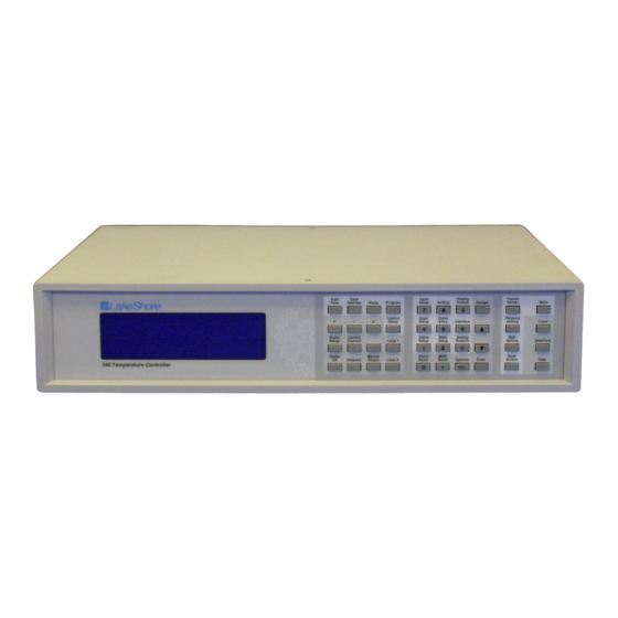
Model 340
Temperature Controller
Lake Shore Cryotronics, Inc.
575 McCorkle Blvd.
Westerville, Ohio 43082-8888 USA
Internet Addresses:
sales@lakeshore.com
service@lakeshore.com
Visit Our Website:
www.lakeshore.com
Fax: (614) 891-1392
Telephone: (614) 891-2243
P/N 119-011
29 March 2004
Advertisement
Table of Contents
Troubleshooting

Related Manuals for Lakeshore 340


Summary of Contents for Lakeshore 340
- Page 1 User’s Manual Model 340 Temperature Controller Lake Shore Cryotronics, Inc. 575 McCorkle Blvd. Westerville, Ohio 43082-8888 USA Internet Addresses: sales@lakeshore.com service@lakeshore.com Visit Our Website: www.lakeshore.com Fax: (614) 891-1392 Telephone: (614) 891-2243 Methods and apparatus disclosed and described herein have been developed solely on company funds of Lake Shore Cryotronics, Inc.
- Page 2 Limited Warranty specified above. Any unauthorized duplication legal rights and you might also have other rights that vary from or use of the Model 340 firmware in whole or in part, in print, or in any country to country, state to state or province to province.
-
Page 3: Declaration Of Conformity
Lake Shore Model 340 Temperature Controller User’s Manual Declaration of Conformity Lake Shore Cryotronics, Inc. 575 McCorkle Blvd. Westerville, OH 43082-8888 USA hereby declare that the equipment specified conforms to the following Directives and Standards: Application of Council directives: ....... 73/23/EEC 89/336/EEC Standard to which Conformity is declared:.. - Page 4 Lake Shore Model 340 Temperature Controller User’s Manual This Page Intentionally Left Blank...
-
Page 5: Table Of Contents
TABLE OF CONTENTS Chapter/Paragraph Title Page INTRODUCTION ..............................1-1 GENERAL ............................1-1 TEMPERATURE CONTROL SYSTEM ..................... 1-2 TEMPERATURE CONTROL SYSTEM WITH THE MODEL 340 ............1-2 1.2.1 Cooling Source ..........................1-2 1.2.2 Feedback ............................1-3 1.2.3 Control Equation ..........................1-3 1.2.4... - Page 6 Lake Shore Model 340 Temperature Controller User’s Manual TABLE OF CONTENTS (Continued) Chapter/Paragraph Title Page 2.6.2 Integral (I)............................2-9 2.6.3 Derivative (D) ..........................2-9 2.6.4 Manual Heater Output........................2-11 MANUAL TUNING ........................... 2-11 2.7.1 Setting Heater Range........................2-11 2.7.2 Tuning Proportional........................2-11 2.7.3...
- Page 7 Lake Shore Model 340 Temperature Controller User’s Manual TABLE OF CONTENTS (Continued) Chapter/Paragraph Title Page 4.4.3 Using Setting Screens ........................4-4 4.4.4 Data Entry Screens ........................4-4 4.4.5 The Help Key ..........................4-4 4.4.6 Keypad Time-out..........................4-4 4.4.7 Key Definitions ..........................4-5 CHANGING DISPLAY FORMAT .......................
- Page 8 Lake Shore Model 340 Temperature Controller User’s Manual TABLE OF CONTENTS (Continued) Chapter/Paragraph Title Page 6.13 CONTROL OUTPUT LIMITS......................6-11 6.13.1 Setpoint Limit ..........................6-11 6.13.2 Control Output Slope Limit ......................6-11 6.13.3 Heater Range Limit ........................6-11 ANALOG OUTPUT, DIGITAL I/O. ALARMS, AND RELAY OPERATION ............7-1 GENERAL ............................
- Page 9 Lake Shore Model 340 Temperature Controller User’s Manual TABLE OF CONTENTS (Continued) Chapter/Paragraph Title Page REMOTE OPERATION ............................9-1 GENERAL ............................9-1 IEEE-488 INTERFACE........................9-1 9.1.1 IEEE-488 Interface Settings......................9-1 9.1.2 IEEE-488 Command Structure....................... 9-1 9.1.3 Status Registers..........................9-3 9.1.4 IEEE Interface Example Programs ....................
- Page 10 Lake Shore Model 340 Temperature Controller User’s Manual TABLE OF CONTENTS (Continued) Chapter/Paragraph Title Page 10.5.3 Operation ........................... 10-13 10.5.3.1 Input Selection........................10-13 10.5.3.2 Displaying Option Readings ....................10-13 10.5.3.3 Curve Selection ........................10-13 10.5.3.4 Range Selection ........................10-13 10.5.3.5 Temperature Coefficient ......................
- Page 11 Model 340 Mounting Holes and Analog Option Plug..............10-6 10-7 Model 3462 Mounting Holes and Analog Plug ................10-6 10-8 Model 340 Rear Panel with Model 3462 Option Card Installed..........10-7 10-9 Model 340 Rear Panel with Model 3464 Option Card Installed..........10-8 11-1 SERIAL I/O RJ-11 Rear Panel Connector Details..............
- Page 12 Lake Shore Model 340 Temperature Controller User’s Manual LIST OF TABLES Table No. Title Page Comparison of Control Loops 1 and 2 ..................1-6 Model 340 Sensor Performance Chart..................1-8 Comparison of Liquid Helium to Liquid Nitrogen................3-3 AC Line Input Definitions.......................3-5 Sensor INPUT A and B Connector Definitions................3-6 Sensor Types Recognized by the Model 340 ................5-1...
-
Page 13: Introduction
United States of America by Lake Shore Cryotronics, Inc. The Lake Shore Model 340 is our most advanced temperature controller to date. It is a result of 25 years of experience in the cryogenics industry and reflects our dedication to customer service. Combined with the complete line of Lake Shore temperature sensors, the Model 340 is one of the most useful and flexible tools available for cryogenic temperature measurement and control. -
Page 14: Temperature Control System
Cooling Source The Model 340 integrates many of the elements of a complete control system. There are a few parts that the Model 340 does not provide. The largest and most notable part missing is a cooling source. The Model 340 provides power to a resistive heater acting as the heating source, but it does not provide cooling. -
Page 15: Feedback
Each of the many different types of temperature sensor has qualities that make it the best choice for some application. The Model 340 has the ability to operate with many different types of sensors so that it is not a limiting factor when deciding which sensor to use. -
Page 16: Input Isolation
Model 340. New readings are taken as often as 20 times a second, the update rate is slower for more complex readings. The display is updated more slowly than data is read because the flicker of fast changes is distracting. -
Page 17: Temperature Response Curves And Calcurves
When a instrument can run one closed loop control system it is referred to as a single loop controller. The Model 340 has a the ability to run a second, independent control loop so it is called a two loop controller. The second loop is used more often to reduce the temperature gradients in one cooling system than run two different cooling systems. -
Page 18: Internal Programming
1.3.13 Alarms, Analog Outputs, and Digital I/O A clear example of the commitment to making the Model 340 a real part of the experimental environment is the inclusion of analog and digital (TTL level) inputs and outputs. These features are not needed for a typical temperature control loop but they provide an effective interface to other experimental hardware at relatively low cost to the user. - Page 19 Lake Shore Model 340 Temperature Controller User’s Manual Thermometry: Number of Inputs: Two included, more optional Measurement Type: Four-lead Differential Standard Sensor Inputs: Silicon Diode, GaAIAs Diode, Platinum RTD, Cernox RTD, Germanium RTD, Carbon-Glass RTD, Ruthenium Oxide, Rhodium Iron, other resistive sensors...
- Page 20 Lake Shore Model 340 Temperature Controller User’s Manual Table 1-2. Model 340 Sensor Input Performance Chart 100 Ω Platinum RTD 100 Ω Platinum RTD 1000 Ω Sensor Type Silicon Diode GaAlAs Diode 250 Ω Full scale 500 Ω Full scale...
- Page 21 Lake Shore Model 340 Temperature Controller User’s Manual Table 1-2. Model 340 Sensor Input Performance Chart (Continued) Sensor Type Rox™ Thermox™ Carbon-Glass™ Cernox™ Germanium Negative Temperature Coefficient Negative Negative Negative Negative Sensor Units Ohms (Ω) Ohms (Ω) Ohms (Ω) Ohms (Ω) Ohms (Ω)
-
Page 22: Model 340 Sensor Performance Chart
Lake Shore Model 340 Temperature Controller User’s Manual Table 1-2. Model 340 Sensor Performance Chart (Continued) Sensor Type Thermocouple 25 mV Thermocouple 50 Capacitance 15 nF Capacitance 150 nF Temperature Coefficient Positive. Positive or Negative. Sensor Units Input Range ±25 mV ±50 mV... -
Page 23: Cooling System Design
Another thing to consider when choosing a temperature sensor is that instruments like the Model 340 are not able to read some sensors over their entire temperature range. Lake Shore sells calibrated sensors that operate down to 50 millikelvin (mK), but the Model 340 is limited to 300 mK in its standard configuration. 2.1.2... -
Page 24: Environmental Conditions
Otherwise the Model 340 operates in sensor units like ohms or volts. The Model 340 may not work over the full temperature range of some sensors. The standard inputs are limited to operation above 300 mK even with sensors that can be calibrated to 50 mK. -
Page 25: Softcal
Model 340 where it is called a temperature response curve. The Model 340 can also perform a SoftCal calibration. The user must provide one, two, or three known temperature reference points. The range and accuracy of the calibration is based on these points. -
Page 26: Standard Curves
Curve data is loaded into some type of non-volatile memory that is installed into the instrument by the user. In the case of the Model 340, the curve is loaded into a non-volatile memory card which can be used for transfer into the instrument. The field installed version is a Model 3405- 128F-CALCRV and it should be ordered with the calibrated sensor. -
Page 27: Thermal Conductivity
Lake Shore Model 340 Temperature Controller User’s Manual 2.3.3 Thermal Conductivity The ability of heat to flow through a material is called thermal conductivity. Good thermal conductivity is important in any part of a cryogenic system that is intended to be the same temperature. Copper and aluminum are examples of metals that have good thermal conductivity, while stainless steel does not. -
Page 28: Lead Wire
Cryogenic cooling systems have a wide range of cooling power. The resistive heater must be able to provide sufficient heating power to warm the system. The Model 340 can supply up to 100 W of power to a heater (if the heater resistance is appropriate). The Model 340 heater output current source has a maximum output of 2 A, limiting maximum power to: Max Power (watts) = (2 A) ×... -
Page 29: Heater Location
Lake Shore Model 340 Temperature Controller User’s Manual Heater Resistance and Power (Continued) Both limits are in place at the same time, so the smallest of the two computations gives the maximum power available to the heater. A heater of 25 Ω allows the instrument to provide its maximum power of 100 watts. -
Page 30: Thermal Lag
If both control stability and measurement accuracy are critical it may be necessary to use two sensors, one for each function. Many temperature controllers including the Model 340 have two sensor inputs for this reason. -
Page 31: Pid Control
As discussed in Paragraph 2.7.3, measuring this time constant allows a reasonable calculation of the integral setting. In the Model 340, the integral term is not set in seconds like some other systems. The integral setting can be derived by dividing 1000 by the integral seconds:... -
Page 32: Examples Of Pid Control
Lake Shore Model 340 Temperature Controller User’s Manual change in setpoint P Only (too high) actual temperature response time P Only P Only (too low) P + I P + I + D 340-2-3.bmp Figure 2-3. Examples of PID Control... -
Page 33: Manual Heater Output
Manual Heater Output (MHP) The Model 340 has a control setting that is not a normal part of a PID control loop. Manual heater output can be used for open loop control, meaning feedback is ignored and the heater output stays at the users manual setting. -
Page 34: Tuning Integral
2.7.3 Tuning Integral When the proportional setting is chosen and the integral is set to zero (off), the Model 340 controls the load temperature below the setpoint. Setting the integral allows the Model 340 control algorithm to gradually eliminate the difference in temperature by integrating the error over time. See Figure 2-3d. An integral setting that is too low causes the load to take too long to reach the setpoint. -
Page 35: Autotuning
AutoTune feature. Once the load temperature is at or near the new setpoint, the Model 340 looks at the logged data to calculate the best P, I, and D setting values. -
Page 36: Zone Tuning
Trying to remember when to use which set of tuning parameters can be frustrating. The Model 340 has a Zone feature as one of its tuning modes that can help. -
Page 37: General
INSTALLATION GENERAL This chapter provides a general layout for the Model 340 rear panel and information on how to make line power, sensor, heater, and interface connections to the Model 340. Refer to Chapter 2 for cooling system wiring. To experiment with software settings covered in the next chapter before doing a complete hardware setup, the Model 340 can be powered with only line power connected. -
Page 38: Safety Summary
Cryotronics, Inc. assumes no liability for Customer failure to comply with these requirements. The Model 340 protects the operator and surrounding area from electric shock or burn, mechanical hazards, excessive temperature, and spread of fire from the instrument. Environmental conditions outside of the conditions below may pose a hazard to the operator and surrounding area. -
Page 39: Handling Liquid Helium And Liquid Nitrogen
Handling Liquid Helium and Liquid Nitrogen Liquid Helium (LHe) and liquid nitrogen (LN ) may be used in conjunction with the Model 340. Although not explosive, the following paragraphs provide safety considerations in the handling of LHe and LN 3.1.5.1... -
Page 40: Rear Panel Definition
Keep warm and rest. Call a physician immediately. REAR PANEL DEFINITION This paragraph provides a summary of Model 340 rear panel connections. See Figure 3-2. CAUTION Verify that the AC Line Voltage shown in the window on the fuse holder corresponds to that marked on the rear panel, and that both these settings are appropriate for the intended AC power input. -
Page 41: Line Input Assembly
It is important to verify that the Indicator Line Voltage Range Fuse (slow blow) Model 340 is set to the appropriate line voltage and has the correct line fuse before it is 90-105 VAC powered on for the first time. Refer to Table 3-2. -
Page 42: Fuse Replacement
STANDARD SENSOR INPUTS This paragraph details how to connect sensors to the standard Model 340 inputs. These inputs operate with most resistive and diode sensors. Refer to Paragraph 5.1 to configure inputs for a sensor type with software. -
Page 43: Sensor Lead Cable
Shielding the sensor lead cable is important to keep external noise from entering the measurement. A shield is most effective when it is near the measurement potential so the Model 340 offers a driven shield that stays close to the measurement. The shield of the sensor cable should be connected to the shield pin of the input connector. -
Page 44: Two-Lead Sensor Measurement
Loop 1 Output The Model 340 has two control loops. Loop 1 can be considered a primary loop because it is capable of driving 100 W of heater power. The heater output for Loop 1 is a traditional control output for a cryogenic temperature controller. -
Page 45: Heater Output Wiring For Loop 1
Some systems require little heater power which requires only a small amount of current. Even though the Model 340 has software current limits, the user may wish to put a smaller fuse into the heater fuse holder to protect against inadvertent changes in instrument settings. -
Page 46: Loop 2 Output
Loop 2 Output The Model 340 has a second control loop called Loop 2. Loop 2 is an auxiliary control loop with enough features to control a radiation shield or small sample heater. Loop 2 has a different output from Loop 1, it uses Analog Output 2 as its actuator. -
Page 47: Boosting The Output Power
There are temperature control systems that require more power than the Model 340 can provide. An auxiliary DC power supply can be used to boost the output of the Model 340. Programmable power supplies are available that use a low current programming voltage as an input to control a high current voltage output. -
Page 48: Digital I/O
RELAYS Slides into RELAYS slot screwdriver in rear of Model 340 The Model 340 has one high and one low relay, shown in to lock or unlock wires Figure 3-7. They are most commonly associated with the alarm feature. The relays can also be put in manual... -
Page 49: Front Panel Operation
DISPLAY FORMATS The Model 340 has an eight line by 40 character LCD graphic display capable of showing small (6 × 8) and large (12 × 16) characters. This display is very flexible and provides the user feedback at each step of operation. -
Page 50: Normal Display
KEYPAD DESCRIPTION The Model 340 has 40 keys on its keypad which help prompt the operator in using the large number of powerful software features. This section will help the user understand the keypad layout and how to quickly get to the features of interest. -
Page 51: Keypad Navigation
Lake Shore Model 340 Temperature Controller User’s Manual Keypad Description (Continued) Aside from the key location, the color of the panel behind the key is also important. Direct settings, made with the normal display showing, are initiated using keys with a gray background. The number keys and the gray backed Enter, Escape, up (s), or down (t) keys are used to complete these operations when needed. -
Page 52: Using Setting Screens
4.4.6 Keypad Time-out The Model 340 suspends some of its operation during keypad operation. (The control loop and computer interfaces are never disabled.) A time-out was put in the keypad so that the instrument would return to normal operation if a key happened to be unintentionally pressed. The time-out acts like an Escape or Cancel Screen key being pressed so that no accidental changes are made to settings. -
Page 53: Key Definitions
Lake Shore Model 340 Temperature Controller User’s Manual 4.4.7 Key Definitions Description Displays the AUTO TUNE screen to set Auto P, Auto PI, or Auto PID control mode. AutoTune Displays the ZONE SETTINGS screen which specifies P, I, D, Manual Output, and Zone Settings Heater Range for up to 10 Temperature control zones. -
Page 54: Changing Display Format
Number of Readings Displayed The Model 340 can display between one and eight input readings at a time. If one to four readings are chosen, they will be shown with the large characters. If five to eight readings are chosen, they will be shown with small characters. -
Page 55: Reading Source And Display Units
4.5.4 Control Loop Display The Model 340 has the ability to operate one or two temperature control loops. The user has the option of displaying parameters from either one or both loops. When both loops are displayed, fewer parameters are shown on the normal display. -
Page 56: Heater Output Display Units
Revision Information screen is displayed. Up the s or t key to change the Set Defaults setting to Yes, then press the Enter key. Press the Save Screen key to complete the action. The Model 340 will then restart using the factory default values. -
Page 57: Sensor Input And Temperature Measurement Operation
To proceed to temperature response curve selection (Paragraph 5.2), press Previous Setting or press Save Screen to store the changes in the Model 340. The default setting is Silicon Diode. NOTE: If the user changes any of the parameters listed for a standard sensor type, the instrument assumes a special sensor type is required (Paragraph 5.1.4). -
Page 58: Voltage Excitation (Current Autorange)
When these sensors are being read by the Model 340, the current excitation is automatically ranged to keep the voltage across the sensor below that listed in the table above. To illustrate the effect,... -
Page 59: Turning An Input Off
Some types of sensors behave in a predictable manner and a standard temperature response curve can be created for them. The Model 340 has standard curves included in firmware. Refer to Table 5-3. Details on standard curves are provided in Appendix B. -
Page 60: Filter And Math
Filter The Model 340 can apply an averaging filter to any sensor input. The filter is designed to prevent electronic noise that is picked up on the sensor lead wires from showing on the display. It is enabled or disabled for all of the reading formats of an input at the same time. -
Page 61: Max/Min
Use the s or t key to select one of the four sources. Press the Next Setting key to make other changes. Press the Save Screen key to store the change in the Model 340. The default settings are On, kelvin. -
Page 62: Linear Equation
5.3.3 Linear Equation The Model 340 can calculate a linear equation as a special data processing feature. The output of this calculation can be shown on the display or directed to an analog output for proportional control of other hardware in an experiment. One computation can be done for each sensor input. The output will not automatically show on the display, use the display format setting screen described in Paragraph 4.5 to... -
Page 63: Input Setup With A Scan Mode Active
The Model 340 can set its digital outputs to the corresponding scan channel. If the external scanner has digital control inputs the Model 340 can be used to select a channel. This is a convenient way to synchronize the scanned readings or automate the scan operation using only the interface of the Model 340. -
Page 64: Auto Scanning
Model 340 can set its digital outputs to the corresponding Auto Scan channel. If the external scanner has digital control inputs the Model 340 can be used to select a channel. This is a convenient way to synchronize the scanned readings or automate the scan operation using only Model 340. -
Page 65: Temperature Control Operation
The Model 340 has the ability to run two independent control loops, so it is called a two-loop controller. Loop 1 is the primary control loop, capable of sourcing more power and has additional software features. The heater output for Loop 1 is a traditional control output for a cryogenic temperature controller. -
Page 66: Control Output Display
6.1.4 Control Output Display The Model 340 shows the control output value on the display so the operator can monitor the control loop performance during an experiment or while tuning. The output value is shown on the display whenever loop parameters for that loop are shown. -
Page 67: Control Channel
If the user changes the control channel without selecting a temperature response curve for both the old and new Channel, the Model 340 sets control units to sensor units and picks the sensor units reading from the new control channel as the new Setpoint. -
Page 68: Manual Setting Of Pid Control Parameters
Lake Shore Model 340 Temperature Controller User’s Manual MANUAL SETTING OF PID CONTROL PARAMETERS This section describes entry of PID control parameters into the Model 340. To select Manual PID control mode, refer to Paragraph 6.5. 6.6.1 Proportional (P) The proportional parameter (also called gain) is the P part of the PID control equation. It has a range of 0 to 1000 with a resolution of 0.1. -
Page 69: Zone Control Data Entry
Manual PID. ZONE CONTROL DATA ENTRY The Model 340 allows the user to establish up to 10 custom temperature zones where the controller automatically uses pre-programmed PID settings and heater range. The user should configure the zones using 1 as the lowest to 10 as the highest zone in kelvin (K). -
Page 70: Record Of Zone Settings
Lake Shore Model 340 Temperature Controller User’s Manual Zone Setting WorkSheet Zone 10 Setpoint: Gain ( P ) Reset ( I ) Rate ( D ) Manual Output Heater Range Zone 09 Setpoint: Gain ( P ) Reset ( I ) -
Page 71: Using Open Loop Control
Control channel readings can display in any units. Display units need not match setpoint units. When changing setpoint units while the control loop is active, the Model 340 converts the control setpoint to the new control units for minimal disruption in control output. -
Page 72: Setpoint Ramping
On. Press the Next Setting key to highlight the ramp rate field. Use the number keys to enter a ramp rate value and press the Save Screen key to save the changes in the Model 340. The default setting is Off, 0.1. -
Page 73: Full Scale Heater Power At Typical Resistance
Lake Shore Model 340 Temperature Controller User’s Manual The maximum current parameter is included in the Model 340 to make it more compatible with existing cooling systems. Even though this instrument is capable of sourcing two amps of heater current, there are many control loads that will not tolerate that much current. -
Page 74: Analog Output As Loop 2 Control Output
LOOP. Press Enter or Next Setting to continue with more settings or the Save Screen key to save the changes to the Model 340. It is recommended to set the Analog Output to unipolar mode. Few applications can use bipolar control output. -
Page 75: Control Output Limits
Celsius. The limit does not work when sensor units are chosen for the setpoint. The Model 340 turns off the control output if the temperature of the control sensor exceeds the global limit. The global setpoint limit works along with the individual limits that can be entered in a temperature response curve. - Page 76 Lake Shore Model 340 Temperature Controller User’s Manual This Page Intentionally Left Blank 6-12 Temperature Control Operation...
-
Page 77: Analog Output, Digital I/O. Alarms, And Relay Operation
ANALOG OUTPUTS The Model 340 has two analog outputs, Analog Output 1 and Analog Output 2. They are voltage sources that can be used to output a voltage representation of sensor input reading. Analog Output 2 can also be used as the control output for Loop 2 as described in Paragraph 7.1.3. -
Page 78: Input Mode For Analog Output
Lake Shore Model 340 Temperature Controller User’s Manual 7.1.1 Input Mode for Analog Output When input mode is chosen for an analog Input Sensor Input used for input reading data. The default setting is A. output, there are several Source Source of data from the input. -
Page 79: Manual Mode Operation Of The Analog Outputs
DIGITAL INPUTS AND OUTPUTS (I/O) The Model 340 has six digital inputs and five digital outputs. The digital inputs and outputs can be used to monitor instrument status in a pre-programmed mode of operation or they can also be used in manual mode to control and monitor external events. -
Page 80: Digital Outputs In Manual Mode
INPUT ALARMS Each input of the Model 340 has a high and low alarm setting. Input reading data in temperature units, sensor units, or from linear equation can be compared to the alarm values. If a reading is higher than the high alarm setting the high alarm is active for the input. -
Page 81: Selecting An Input Alarm Source
Input Alarm Relay Setup The two relays on the Model 340 can be used for high and low alarm outputs. One or more sets of high and low input alarms can be directed to the high and low relays. To direct the alarms from an input to the relays, set the relay parameter on the ALARM SETTINGS screen to On. -
Page 82: Input Alarm Reset
Save Screen key to store the change. The default setting is On. HIGH AND LOW RELAYS The Model 340 has one high and one low Relay is set to Off relay. See Figure 3-7. They are most MANUAL Relay manual control (Paragraph 7.4.2) -
Page 83: Instrument Programming
The Model 340 has 40 user curve locations numbered 21 thru 60. Each location can hold from 2 to 200 data pairs (breakpoints) including a value in sensor units and a corresponding value in Kelvin. Using fewer than 200 breakpoints will not increase the number of available curve locations. -
Page 84: Front Panel Curve Edit
Lake Shore Model 340 Temperature Controller User’s Manual 8.1.3 Front Panel Curve Edit The Edit curve operation can be used to enter a new curve or edit an existing user curve. Entering the identification parameters associated with the curve is as important as entering the breakpoints. Only user curves (numbers 21 to 60) can be changed. -
Page 85: Front Panel Curve Copy
The breakpoints should be entered with the sensor units value increasing as point number increases. There should not be any breakpoint locations left blank in the middle of a curve. The search routine in the Model 340 interprets a blank breakpoint as the end of the curve. -
Page 86: Softcal
Lake Shore generates SoftCal calibration points in a controlled calibration facility for best accuracy. The user enters the calibration points into the Model 340 to generate a curve. If the user buys the CalCurve service with the calibrated sensor, the factory generates the curve for later entry like any other curve. -
Page 87: Softcal Accuracy With Silicon Diode Sensors
Lake Shore Model 340 Temperature Controller User’s Manual 8.2.2 SoftCal Accuracy with Silicon Diode Sensors SoftCal allows an abbreviated calibration, based on 1, 2, or 3 points, to generate a voltage-versus- temperature curve over the useful range of a Lake Shore DT-400 Series silicon diode sensor. -
Page 88: Creating A Softcal Calibration Curve
The internal program feature works with control Loop 1. There is enough memory in the Model 340 to hold 100 programming instructions. The instructions can be put in up to 10 different program locations. The program locations are provided to help organize internal programming operations. - Page 89 Lake Shore Model 340 Temperature Controller User’s Manual 8.3.1.1 Ramp Setpoint Absolute Ramp the control setpoint from its present setting value to a new specified (absolute) setting value. The setpoint units must be in temperature for this instruction to operate. The ramp can be done at a specified ramp rate or in a specified length of time.
- Page 90 8.3.1.6 Digital Output A Model 340 internal program can interact with experimental parameters other than temperature. The digital outputs can be used to control outside events while a program is running. Using digital outputs in programs is not available if external scanner operation is enabled.
- Page 91 Lake Shore Model 340 Temperature Controller User’s Manual 8.3.1.9 Settle Temperature control systems often need time for temperature control to stabilize or temperature gradients to settle out. The Settle instruction is used in a program to add a time delay or let the control temperature settle.
-
Page 92: Internal Programming Operations
Lake Shore Model 340 Temperature Controller User’s Manual 8.3.2 Internal Programming Operations Below is a list of the four internal programming operations initiated from the PROGRAM MODE screen: Run a program. Run program Terminate program End a program run and return instrument to normal operation. -
Page 93: Saving A Program
Lake Shore Model 340 Temperature Controller User’s Manual 8.3.4 Saving a Program When a program is entered, it is automatically saved. The Save Screen key must be pressed when changing from the right side of the display to the left, or instruction parameter settings will be lost. -
Page 94: Example Of Using Subprograms (Example 2)
Lake Shore Model 340 Temperature Controller User’s Manual Programmed Actual Cool Down minutes Program 4 5 6 7 8 5 6 7 8 5 6 7 8 9 Instructions 340-8-3.CVS Figure 8-3. Sample Program #1 8.3.7 Example of Using Subprograms (Example 2) This is an example of a short subprogram that could easily be called from the program in example 1. -
Page 95: Clear Internal Program Memory
DATA CARD OPERATION The Model 340 has a data card slot located on the left side of the real panel, underneath the power input assembly. Although the pins in the data card slot conform to the PCMCIA standard, the slot is not a PCMCIA interface. - Page 96 1 to 3600 seconds. The interval number is set first followed by units. readings/seconds Selects the unit of the logging rate. Every 20 readings equals 1 second, because the Model 340 updates the readings 20 times a second. Start Mode Selecting Clear clears old records before starting data logging. Selecting Continue continues data logging and adds new records to existing data.
- Page 97 8.4.1.6 Line Power Loss When line power is lost while the Model 340 is logging data, it resumes the data log sequence when power is restored, if the battery in the SRAM Data Card has enough voltage to keep the logged data.
-
Page 98: Reading From A Data Card
Select the CalCurve from the data card and the curve location in the Model 340. Reads the Model 340 Main Code from the M340 Main Code data card and resets the Model 340. Used to receive factory software updates. 8.4.3 Writing To A Data Card... -
Page 99: Remote Operation
A LISTENER receives data from other devices through the bus. The BUS CONTROLLER designates to the devices on the bus which function to perform. The Model 340 performs the functions of TALKER and LISTENER but cannot be a BUS CONTROLLER. The BUS CONTROLLER is your digital computer which tells the Model 340 which functions to perform. - Page 100 LLO (Local Lockout) – LLO is sent to instruments to lock out (prevent the use of) their front panel controls. DCL (Device Clear) – DCL is used to clear Model 340 interface activity and put it into a bus idle state.
-
Page 101: Status Registers
A&B If the Service Request is enabled, any of these bits being set causes the Model 340 to pull the SRQ management low to signal the BUS CONTROLLER. These bits are reset to zero upon a serial poll of the Status Byte Register. -
Page 102: Ieee Interface Example Programs
Operation Complete (OPC) Bit (0) – This bit is generated in response to the QOPC common command. It indicates when the Model 340 has completed all selected pending operations. 9.1.4 IEEE Interface Example Programs Two BASIC programs are included to illustrate the IEEE-488 communication functions of the instrument. -
Page 103: Gpib Setting Configuration
Lake Shore Model 340 Temperature Controller User’s Manual Figure 9-1. GPIB Setting Configuration Figure 9-2. DEV 12 Device Template Configuration Remote Operation... -
Page 104: Visual Basic Ieee-488 Interface Program Setup
Lake Shore Model 340 Temperature Controller User’s Manual 9.1.4.2 Visual Basic IEEE-488 Interface Program Setup This IEEE-488 interface program works with Visual Basic 6.0 (VB6) on an IBM PC (or compatible) with a Pentium-class processor. A Pentium 90 or higher is recommended, running Windows 95 or better. It assumes your IEEE-488 (GPIB) card is installed and operating correctly (refer to Paragraph 9.1.4.1). -
Page 105: Ieee-488 Interface Program Control Properties
Lake Shore Model 340 Temperature Controller User’s Manual Table 9-1. IEEE-488 Interface Program Control Properties Current Name Property New Value Label1 Name lblExitProgram Caption Type “exit” to end program. Label2 Name lblCommand Caption Command Label3 Name lblResponse Caption Response Text1... -
Page 106: Visual Basic Ieee-488 Interface Program
Lake Shore Model 340 Temperature Controller User’s Manual Table 9-2. Visual Basic IEEE-488 Interface Program Public gSend As Boolean 'Global used for Send button state Private Sub cmdSend_Click() 'Routine to handle Send button press gSend = True 'Set Flag to True... -
Page 107: Ieee-488 Interface Board Installation For Quick Basic Program
Lake Shore Model 340 Temperature Controller User’s Manual 9.1.4.3 IEEE-488 Interface Board Installation for Quick Basic Program This procedure works on an IBM PC (or compatible) running DOS or in a DOS window. This example uses the National Instruments GPIB-PCII/IIA card. -
Page 108: Typical National Instruments Gpib Configuration From Ibconf.exe
Lake Shore Model 340 Temperature Controller User’s Manual National Instruments National Instruments GPIB0 Configuration GPIB-PC2/2A Ver 2.1 Primary GPIB Address ..Primary GPIB Address ..à à 0 0 Select the primary GPIB address by é é Secondary GPIB Address ..NONE Secondary GPIB Address .. -
Page 109: Quick Basic Ieee-488 Interface Program
Lake Shore Model 340 Temperature Controller User’s Manual Table 9-3. Quick Basic IEEE-488 Interface Program IEEEEXAM.BAS EXAMPLE PROGRAM FOR IEEE-488 INTERFACE This program works with QuickBasic 4.0/4.5 on an IBM PC or compatible. The example requires a properly configured National Instruments GPIB-PC2 card. The REM $INCLUDE statement is necessary along with a correct path to the file QBDECL.BAS. -
Page 110: Program Operation
Lake Shore Model 340 Temperature Controller User’s Manual 9.1.4.5 Program Operation Once either example program is running, try the following commands and observe the response of the instrument. Input from the user is shown in bold and terminators are added by the program. The word [term] indicates the required terminators included with the response. -
Page 111: Serial Interface Overview
Lake Shore Model 340 Temperature Controller User’s Manual SERIAL INTERFACE OVERVIEW The serial interface used in the Model 340 is commonly referred to as an RS-232C interface. RS-232C is a standard of the Electronics Industries Association (EIA) that describes one of the most common interfaces between computers and electronic equipment. -
Page 112: Hardware Support
9.2.3 Hardware Support The Model 340 interface hardware supports the following features. Asynchronous timing is used for the individual bit data within a character. This timing requires start and stop bits as part of each character so the transmitter and receiver can resynchronized between each character. Half duplex transmission allows the instrument to be either a transmitter or a receiver of data but not at the same time. -
Page 113: Message Flow Control
Lake Shore Model 340 Temperature Controller User’s Manual Message Strings (Continued) A query string is issued by the computer and instructs the instrument to send a response. The query format is: <query mnemonic><?><space><parameter data><terminators>. Query mnemonics are often the same as commands with the addition of a question mark. Parameter data is often unnecessary when sending queries. -
Page 114: Visual Basic Serial Interface Program Setup
Lake Shore Model 340 Temperature Controller User’s Manual 9.2.7.1 Visual Basic Serial Interface Program Setup The serial interface program works with Visual Basic 6.0 (VB6) on an IBM PC (or compatible) with a Pentium- class processor. A Pentium 90 or higher is recommended, running Windows 95 or better, with a serial interface. -
Page 115: Serial Interface Program Control Properties
Lake Shore Model 340 Temperature Controller User’s Manual Table 9-5. Serial Interface Program Control Properties Current Name Property New Value Label1 Name lblExitProgram Caption Type “exit” to end program. Label2 Name lblCommand Caption Command Label3 Name lblResponse Caption Response Text1... -
Page 116: Visual Basic Serial Interface Program
Lake Shore Model 340 Temperature Controller User’s Manual Table 9-6. Visual Basic Serial Interface Program Public gSend As Boolean 'Global used for Send button state Private Sub cmdSend_Click() 'Routine to handle Send button press gSend = True 'Set Flag to True... -
Page 117: Quick Basic Serial Interface Program Setup
Lake Shore Model 340 Temperature Controller User’s Manual 9.2.7.2 Quick Basic Serial Interface Program Setup The serial interface program listed in Table 9-7 works with QuickBasic 4.0/4.5 or Qbasic on an IBM PC (or compatible) running DOS or in a DOS window with a serial interface. It uses the COM1 communication port at 9600 Baud. -
Page 118: Program Operation
Lake Shore Model 340 Temperature Controller User’s Manual 9.2.7.3 Program Operation Once either example program is running, try the following commands and observe the response of the instrument. Input from the user is shown in bold and terminators are added by the program. The word [term] indicates the required terminators included with the response. -
Page 119: Ieee-488/Serial Interface Commands
Lake Shore Model 340 Temperature Controller User’s Manual IEEE-488/SERIAL INTERFACE COMMANDS The IEEE-488/Serial Interface command list that follows is grouped by function with the most often used commands listed first. The actual list of commands is presented in alphabetical order. Parameter conventions used in the command list are as follows: <??? enable>... - Page 120 Lake Shore Model 340 Temperature Controller User’s Manual Command Function Page Command Function Page SETTLE Set Loop 1 Settle........41 Common Commands SETTLE? Query Loop 1 Settle ......41 Process Last Query Received....23 TUNEST? Query Tuning Status ......42 *CLS Clear Interface........23...
- Page 121 *ESR? Returned: <ESR bit weighting>. Format: nnn[term] Remarks: Queries for various Model 340 error conditions and status. The integer returned represents the sum of the bit weighting of the event flag bits in the Standard Event Status Register. Bit Weighting...
- Page 122 Lake Shore Model 340 Temperature Controller User’s Manual Operation Complete Command QOPC Input: *OPC Returned: Nothing Remarks: Generates an Operation Complete event in the Standard Event Status Register upon completion of all pending selected device operations. Query Operation Complete QOPC?
- Page 123 Lake Shore Model 340 Temperature Controller User’s Manual Query Self-Test QTST? Input: *TST? Returned: 0 or 1. Format: n[term] Remarks: The Model 340 performs a self-test at power-up. 0 = no errors found, 1 = errors found. Wait-to-Continue QWAI Input: *WAI Returned: Nothing Remarks: This command is not supported in the Model 340.
- Page 124 Lake Shore Model 340 Temperature Controller User’s Manual ANALOG Configure Analog Output Parameters Input: ANALOG <output>, [<bipolar enable>], [<mode>], [<input>], [<source>], [<high value>], [<low value>], [<manual value>] Returned: Nothing Remarks: Configures the analog output parameters. <output> Specifies which analog output to configure.
- Page 125 Lake Shore Model 340 Temperature Controller User’s Manual BUSY? Query Instrument Busy Status Input: BUSY? Returned: <instrument busy status>. Format: n[term] Remarks: Indicates that the instrument is busy performing a lengthy operation like generating a SoftCal curve, writing to the Flash chip, etc. Commands that use the Instrument Busy Status say so in their description.
- Page 126 Lake Shore Model 340 Temperature Controller User’s Manual CLIMIT Configure Control Loop Limit Parameters Input: CLIMIT <loop>, [<SP limit value>], [<positive slope value>], [<negative slope value>], [<max current>], [<max range>] Returned: Nothing Remarks: Configure control loop limits. <loop> Specifies which loop to configure.
- Page 127 Lake Shore Model 340 Temperature Controller User’s Manual COMM? Query Serial Interface Parameters Input: COMM? Returned: <terminator>, <bps>, <parity>. Format: n,n,n[term] Remarks: Returns the serial interface parameter. See COMM command for parameter descriptions. CRDG? Query Input Celsius Reading Input: CRDG? <input>...
- Page 128 Lake Shore Model 340 Temperature Controller User’s Manual CRVPT? Query Curve Data Point Input: CRVPT? <curve>, <index> Returned: <units value>, <temp value>. Format: ±nnn.nnnE±n,±nnn.nnnE±n[term] Remarks: Returns a standard or user curve data point. See CRVPT command for parameter descriptions. <curve> Specifies which curve to query. Valid entries: 1 - 60.
- Page 129 Lake Shore Model 340 Temperature Controller User’s Manual DFLT Set To Factory Defaults Input: DFLT 99 Returned: Nothing Remarks: Sets all configuration values to factory defaults and resets the instrument. The 99 is required to prevent accidentally setting the unit to defaults. May take some time; use the BUSY? command to determine completion.
- Page 130 Lake Shore Model 340 Temperature Controller User’s Manual DOUT? Query Digital Output Parameters Input: DOUT? Returned: <mode>, <bit weighting>. Format: n,nnn[term] Remarks: Returns the digital output parameters. See the DOUT command for parameter descriptions. FILTER Configure Input Filter Parameters Input: FILTER <input>, [<off/on >], [<points>], [<window>]...
- Page 131 Lake Shore Model 340 Temperature Controller User’s Manual INCRV Configure Input Curve Number Input: INCRV <input>, <curve number> Returned: Nothing Remarks: Specifies the curve an input uses for temperature conversion. <input> Specifies which input to configure. <curve number> Specifies which curve the input uses. If specified curve parameters do not match the input, the curve number defaults to 0.
- Page 132 Lake Shore Model 340 Temperature Controller User’s Manual <range> Specifies the input range (refer to Paragraph 5.1.4). This parameter has a predetermined value based on <type>. If this parameter is supplied, <type> changes to 0 (Special). Valid entries are (given in volts):...
- Page 133 Lake Shore Model 340 Temperature Controller User’s Manual LINEAR? Query Input Linear Equation Parameters Input: LINEAR? <input> Returned: <equation>, <varM value>, <X source>, <B source>, <varB value> Format: n,±nnn.nnn,n,n,±nnn.nnn[term] Remarks: Returns input linear equation configuration. See the LINEAR command for parameter descriptions.
- Page 134 <heater range> Heater range in [W]. 0.0 when heater is OFF (5) point type = None If there is no valid SRAM Data card mounted or data logging is in progress, the Model 340 returns 0,0,0,0,0,0,0,0. Remarks: Returns the record of the specified point of the specified record number.
- Page 135 Remarks: Configures the remote interface mode. <mode> specifies which mode to operate. Valid entries: 1 = local, 2 = remote, 3 = remote with local lockout. Example: MODE 2[term] - Places the Model 340 into remote mode. MODE? Query Remote Interface Mode...
- Page 136 Lake Shore Model 340 Temperature Controller User’s Manual MOUT? Query Control Loop Manual Output Values Input: MOUT? <loop> Returned: <manual output value>. Format: ±nnn.nn[term] Remarks: Returns the control loop manual output value. <loop> specifies which loop to query. Add A Program Line Input: PGM <program>, <command>, [<param1>], [<param2>],...
- Page 137 Lake Shore Model 340 Temperature Controller User’s Manual PGMRUN? Query Program Status. Input: PGMRUN? Returned: <program>,<status>. Format: nn,n[term] Remarks: Returns the current program running and the status. If <program> = 0, no program is running. Values for <status> include: 0 - No errors...
- Page 138 Lake Shore Model 340 Temperature Controller User’s Manual RANGE? Query Heater Range Input: RANGE? Returned: <range>. Format: n[term] Remarks: Returns the heater range. See the RANGE command for parameter descriptions. RDGST? Query Input Status Input: RDGST? <input> Returned: <reading bit weighting>. Format: nnn[term].
- Page 139 Lake Shore Model 340 Temperature Controller User’s Manual SCAL Generate SoftCal™ Curve Input: SCAL <std>, <dest>, <SN>, <T1 value>, <U1 value>, <T2 value>, <U2 value>, [<T3 value>], [<U3 value>] Returned: Nothing Remarks: Generates a SoftCal curve (Paragraph 8.2). NOTE: Curves are not permanently updated in the curve Flash until a CRVSAV command is issued.
- Page 140 Lake Shore Model 340 Temperature Controller User’s Manual SRDG? Query Sensor Units Reading for an Input Input: SRDG? <input> Returned: <sensor units value>. Format: ±nnn.nnnE±n[term] Remarks: Returns the sensor units reading for an input. <input> Specifies which input to query.
-
Page 141: Options And Accessories
A/Ds and excitation for each sensor. A microprocessor on the card manages the A/D and communication with the Model 340. The card allows the Model 340 to read 4 sensors and use any 1 of the sensors as a control sensor. Includes these features: 3462 •... - Page 142 Heater Output Conditioner. The heater output conditioner is a passive filter which further reduces the already low Model 340 heater output noise. The typical insertion loss for the Model 3003 is 20 dB at line frequency, and >40 dB from double the line frequency up. A 144 mm ×...
-
Page 143: Model 2001 Rj-11 Cable Assembly
25.4 mm (1 inch) long. The 50 watt rating is in dead air. In cryogenic applications, the cartridge heater can handle many times this dead air power rating. Rack Mounting Kit. Mounting brackets, ears, and handles to attach one Model 340 to a RM-1 482.6 mm (19-inch) rack mount cabinet. -
Page 144: Optional Model 2002 Rj-11 To Db-25 Adapter
Lake Shore Model 340 Temperature Controller User’s Manual 43 mm 15.8 mm (1.69 inches) (0.63 inches) 340-10-3.eps Figure 10-3. Optional Model 2002 RJ-11 to DB-25 Adapter Item Description Rack Mount Ear 107-049 2 * Screw, 6-32 x 1/2 Inch 0-035... -
Page 145: Model Dual Standard 3462 Input Option Card
C & D on the display. The original standard inputs remain fully functional. 10.3.1 Field Installation The Model 3462 Option kit adds two optional sensor inputs to the Model 340 instrument rear panel. It includes: • (1) 10-conductor Ribbon Cable •... -
Page 146: Model 340 Mounting Holes And Analog Option Plug
Lake Shore Model 340 Temperature Controller User’s Manual Figure 10-6. Model 340 Mounting Holes and Analog Option Plug 6. With the instrument still standing on its face, turn it to view the inside circuit board. The upper half of the circuit board above the transformer assembly contains four holes where metal standoffs install. -
Page 147: Operation
The Model 3464 Option Card adds two thermocouple inputs to the Model 340 Temperature Controller. They appear on the Model 340 display as C and D. Use them for temperature measurement and control with a wide variety of thermocouple sensors. The standard instrument inputs remain fully functional. -
Page 148: Option Installation
To verify if an option is installed simply view the Model 340 rear panel. Options mount above the normal inputs marked A and B. To identify an option installed in a Model 340, press Options, then press More three times. Option identification displays on the REVISION INFORMATION screen. -
Page 149: Measurement Point Connection
Lake Shore Model 340 Temperature Controller User’s Manual 10.4.3.2 Measurement Point Connection Thermocouples are commonly used in high-temperature applications. Cryogenic use of thermocouples offers some unique challenges. Refer to Paragraph 2.3 for general installation guidelines. Consider the following when using thermocouples at low temperatures: •... -
Page 150: Curve Selection
10.4.4.4 Curve Selection To read temperature from the 3464 option, select a temperature curve for the Model 340. If no curve is selected, the Model 340 reads in sensor units (millivolts), and if the display is configured to show temperature for that channel a NO CURVE message displays for that channel. -
Page 151: Computer Interface Commands
Press Next Setting until the room compensation (Room Comp:) field highlights, then use the s or t key to select on or off. Press Save Screen to store the changes in the Model 340. The default setting is On. -
Page 152: Thermocouple Temperature Curves
To install the 3465 Option into a Model 340 follow the installation procedure in Paragraph 10.3.1. Only one option board can be installed in the Model 340 at a time. To verify which option if any is installed in a Model 340, press Options, then press More three times. -
Page 153: Operation
The Model 340 with a 3465 option does not support temperature conversion so no temperature response curves can be selected. Any feature of the Model 340 that requires temperature to operate is not supported with the 3465 option. Selecting temperature units results in a NO CURVE message or display 0K. -
Page 154: Model 3468 Eight-Channel Input Option Card
Option Installation The 3468 can be installed into a Model 340 at the factory or in the field. To field install a 3468 option follow the installation procedure in Paragraph 10.3.1. Only one option board can be installed in the Model 340 at a time. -
Page 155: Operation
Lake Shore Model 340 Temperature Controller User’s Manual 25-Pin Connector.eps Input Connector (Input C) Input Connector (Input D) DESC. DESC. DESC. DESC. C1I+ C1I– D1I+ D1I– C1V+ C1V– D1V+ D1V– C2I+ C2I– D2I+ D2I– C2V+ C2V– D2V+ D2V– C3I+ C3I–... -
Page 156: Computer Interface Commands
Lake Shore Model 340 Temperature Controller User’s Manual 10.6.5 Computer Interface Commands Most of the computer interface commands used by the Model 340 are independent of installed options or sensor type. The following commands or formats change when the 3468 is installed. - Page 157 Lake Shore Model 340 Temperature Controller User’s Manual Table 10-3. Model 3468 Sensor Input Performance Chart 100 Ω Platinum RTD 1000 Ω Cernox™ RTD Sensor Type Silicon Diode GaAlAs Diode 500 Ω Full scale Platinum RTD Temperature Coefficient Negative Negative...
- Page 158 Lake Shore Model 340 Temperature Controller User’s Manual This Page Intentionally Left Blank 10-18 Options and Accessories...
-
Page 159: Service
This chapter provides general service information for the Model 340 Temperature Controller. There is no calibration procedure for the Model 340. There are no serviceable parts inside the Model 340. If you have any specific problems with your Model 340, please call Lake Shore. -
Page 160: General Maintenance
5 × 20 mm T. Test the fuse with an ohmmeter; do not rely on visual inspection of the fuse. Clean the Model 340 periodically to remove dust, grease and other contaminants. Use the procedure below: 1. -
Page 161: Digital I/O Da-15 Rear Panel Connector Details
Lake Shore Model 340 Temperature Controller User’s Manual DIGITAL I/O 340-11-3.eps Symbol Description Type or Limit Digital Output 1 TTL Output Digital Output 2 TTL Output Digital Output 3 TTL Output Digital Output 4 TTL Output Digital Output 5 TTL Output... -
Page 162: Analog Out 1 And 2 Bnc Rear Panel Connector Details
Lake Shore Model 340 Temperature Controller User’s Manual DESCRIPTION Analog Output, Center Conductor Ground, Connector Shell Figure 11-4. ANALOG OUT 1 & 2 BNC Rear Panel Connector Details INPUT A INPUT B SYMBOL DESCRIPTION I– – Current V– – Voltage... -
Page 163: Ieee-488 Interface Connector
Lake Shore Model 340 Temperature Controller User’s Manual 11.4.1 IEEE-488 Interface Connector Connection to the IEEE-488 Interface connector on the rear of the Model 340 Temperature Controller is made using cables specified in the IEEE-488-1978 standard document. Briefly, the cable has 24 conductors with an outer shield. -
Page 164: Serial Interface Cable And Adapters
To aid in Serial Interface troubleshooting, wiring information for the serial cable assembly and the two mating adapters are provided in Figures 11-8 thru 11-10. The Model 2001 and 2003 are included with the Model 340. The Model 2002 is an option. -
Page 165: Top Of Enclosure Remove And Replace Procedure
Figure 11-11. The EPROM will have a sticker on top with the label SV.HEX and the date. A Non-Volatile Ram Access Memory (NOVRAM) IC (U28) is also included in the Model 340. Please use the following procedure to replace either the EPROM or the NOVRAM. -
Page 166: Error Messages
Lake Shore Model 340 Temperature Controller User’s Manual Figure 11-11. Location Of Internal Components 11.8 ERROR MESSAGES Model 340 error messages during normal operation: Input is not setup. .DISABL. Input has no curve. .NOCURV. Input is at/over full-scale. .S-OVER. Input is zero (does not show up for special or thermocouple sensors). -
Page 167: Firmware Ic Replacement
2. Stand unit on its face. Use the Allen wrench to remove the 4 screws on each side of the covers. 3. Use the small Phillips screwdriver to remove the top cover screws. Your Model 340 may have 1 or 2 screws on the top cover. - Page 168 J3 ribbon cable plug. 8. Remove the two Phillips head screws that secure the Option Board to the Model 340 rear panel. 9. The option board now can be lifted out.
-
Page 169: Updating The Master Firmware From A Data Card
Lake Shore label face-up. Press firmly on the card until it securely engages the slot. 2. The Data Card key on the right edge of the Model 340 keypad transfers the code from the data card to the flash memory. - Page 170 Lake Shore Model 340 Temperature Controller User’s Manual This Page Intentionally Left Blank 11-12 Service...
-
Page 171: A1.0 General
Chromel-AuFe 0.03% Thermocouple ....Table A-7 Curve 10 Chromel-AuFe 0.07% Thermocouple ....Table A-8 Curve 11 DT-670 Silicon Diode ........... Table A-9 Table A-1. Lake Shore DT-470 Standard Curve 10 (Curve 1 in the Model 340) Break- Break- Break- Temp. (K) Volts Temp. - Page 172 Lake Shore Model 340 Temperature Controller User’s Manual Table A-2. Standard DT-500 Silicon Diode Curves (Sensors are no longer in production) Break- D Curve (Curve 2) E1 Curve (Curve 3) point Temp. (K) Volts Temp. (K) Volts 365.0 0.19083 330.0 0.28930...
- Page 173 Lake Shore Model 340 Temperature Controller User’s Manual Table A-4. Type K (Nickel-Chromium vs. Nickel-Aluminum) Thermocouple Curve Break- Temp Break- Temp Break- Temp Break- Temp point point point point -6.45774 3.15 -6.02997 63.5 -2.05503 218.5 29.0181 970.5 -6.45733 3.68 -6.00271 65.5...
- Page 174 Lake Shore Model 340 Temperature Controller User’s Manual Table A-5. Type E (Nickel-Chromium vs. Copper-Nickel) Thermocouple Curve Break- Break- Break- Temp (K) Temp (K) Temp (K) point point point -9.834960 3.15 -8.713010 77.50 0.701295 285.00 -9.834220 3.59 -8.646710 80.00 1.061410 291.00...
- Page 175 Lake Shore Model 340 Temperature Controller User’s Manual Table A-6. Type T (Copper vs. Copper-Nickel) Thermocouple Curve Break- Break- Break- Temp (K) Temp (K) Temp (K) point point point -6.257510 3.15 -5.424100 84.00 0.623032 289.00 -6.257060 3.56 -5.380600 86.50 0.843856 294.50...
- Page 176 Lake Shore Model 340 Temperature Controller User’s Manual Table A-7. Chromel-AuFe0.03% Thermocouple Curve * Breakpoint Temp (K) Breakpoint Temp (K) -4.6667 -2.24537 -4.62838 6.35 -2.06041 -4.60347 8.15 -1.86182 180.5 -4.58043 9.75 -1.66004 -4.53965 12.5 -1.47556 200.5 -4.47226 16.95 -1.0904 -4.43743 19.3...
- Page 177 Lake Shore Model 340 Temperature Controller User’s Manual Table A-8. Chromel-AuFe0.07% Thermocouple Curve Break- Temp Break- Temp Break- Temp point point point -5.279520 3.15 -3.340820 115.00 1.313400 332.50 -5.272030 3.78 -3.253410 119.50 1.511140 341.50 -5.263500 4.46 -3.165360 124.00 1.709250 350.50 -5.253730...
- Page 178 Lake Shore Model 340 Temperature Controller User’s Manual Table A-9. Standard DT-670 Diode Curve Breakpoint Temp. (K) Breakpoint Temp. (K) Breakpoint Temp. (K) 0.090570 500.0 1.01064 87.0 1.19475 20.2 0.110239 491.0 1.02125 81.0 1.24208 17.10 0.136555 479.5 1.03167 75.0 1.26122 15.90...
Need help?
Do you have a question about the 340 and is the answer not in the manual?
Questions and answers