Table of Contents
Advertisement
Quick Links
Methods and apparatus disclosed and described herein have been developed solely on company funds of Lake Shore Cryotronics, Inc. No government
or other contractual support or relationship whatsoever has existed which in any way affects or mitigates proprietary rights of Lake Shore Cryotronics,
Inc. in these developments. Methods and apparatus disclosed herein may be subject to U.S. Patents existing or applied for. Lake Shore Cryotronics,
Inc. reserves the right to add, improve, modify, or withdraw functions, design modifications, or products at any time without notice. Lake Shore shall
not be liable for errors contained herein or for incidental or consequential damages in connection with furnishing, performance, or use of this material.
Revision: 1.5
User's Manual
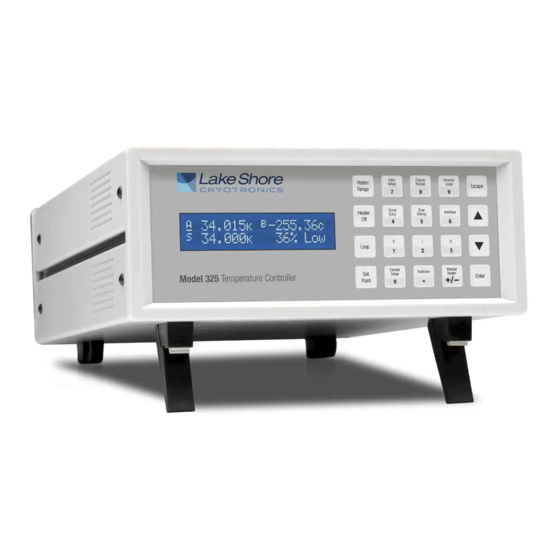
Model 325
Temperature Controller
Lake Shore Cryotronics, Inc.
575 McCorkle Blvd.
Westerville, Ohio 43082-8888 USA
E-mail addresses:
sales@lakeshore.com
service@lakeshore.com
Visit our website at:
www.lakeshore.com
Fax: (614) 891-1392
Telephone: (614) 891-2243
P/N 119-041
12 November 2013
Advertisement
Table of Contents
Troubleshooting

Related Manuals for Lakeshore 325


Summary of Contents for Lakeshore 325
- Page 1 User’s Manual Model 325 Temperature Controller Lake Shore Cryotronics, Inc. 575 McCorkle Blvd. Westerville, Ohio 43082-8888 USA E-mail addresses: sales@lakeshore.com service@lakeshore.com Visit our website at: www.lakeshore.com Fax: (614) 891-1392 Telephone: (614) 891-2243 Methods and apparatus disclosed and described herein have been developed solely on company funds of Lake Shore Cryotronics, Inc. No government or other contractual support or relationship whatsoever has existed which in any way affects or mitigates proprietary rights of Lake Shore Cryotronics, Inc.
- Page 2 Lake Shore Model 335 Temperature Controller User’s Manual LIMITED WARRANTY STATEMENT WARRANTY PERIOD: THREE (3) YEARS Lake Shore warrants that products manufactured by Lake Shore (the "Product") will be free from defects in materials and workmanship for three years from the date of Purchaser's physical receipt of the Product (the "Warranty Period"). If Lake Shore receives notice of any such defects during the Warranty Period and the defective Product is shipped freight prepaid back to Lake Shore, Lake Shore will, at its option, either repair or replace the Product (if it is so defective) without charge for parts, service labor or associated customary return shipping cost to the Purchaser.
- Page 3 FIRMWARE LIMITATIONS Lake Shore has worked to ensure that the Model 325 firmware is as free of errors as possible, and that the results you obtain from the instrument are accurate and reliable. However, as with any computer-based software, the possibility of errors exists.
- Page 4 Lake Shore Model 325 Temperature Controller User’s Manual...
- Page 5 To qualify for the CE Mark, the Model 325 meets or exceeds the requirements of the European EMC Directive 89/336/EEC as a CLASS A product. A Class A product is allowed to radiate more RF than a Class B product and must include the following warning: WARNING: This is a Class A product.
-
Page 7: Table Of Contents
Lake Shore Model 325 Temperature Controller User’s Manual TABLE OF CONTENTS Chapter/Section Title Page INTRODUCTION ..............................1-1 PRODUCT DESCRIPTION ....................... 1-1 SENSOR SELECTION ........................1-4 SPECIFICATIONS ..........................1-6 SAFETY SUMMARY ......................... 1-8 SAFETY SYMBOLS .......................... 1-9 COOLING SYSTEM DESIGN ..........................2-1 GENERAL ............................ - Page 8 Lake Shore Model 325 Temperature Controller User’s Manual TABLE OF CONTENTS (Continued) Chapter/Section Title Page INSTALLATION ..............................3-1 GENERAL ............................3-1 INSPECTION AND UNPACKING ...................... 3-1 REAR PANEL DEFINITION ....................... 3-2 LINE INPUT ASSEMBLY ........................3-3 3.3.1 Line Voltage ........................... 3-3 3.3.2...
- Page 9 Lake Shore Model 325 Temperature Controller User’s Manual TABLE OF CONTENTS (Continued) Chapter/Section Title Page TEMPERATURE CONTROL ......................4-13 4.6.1 Control Loops ..........................4-13 4.6.2 Control Modes ..........................4-14 4.6.3 Tuning Modes ..........................4-14 CONTROL SETUP .......................... 4-15 MANUAL TUNING ........................... 4-16 4.8.1...
- Page 10 Lake Shore Model 325 Temperature Controller User’s Manual TABLE OF CONTENTS (Continued) Chapter/Section Title Page SERIAL INTERFACE OVERVIEW ....................6-15 6.2.1 Physical Connection ........................6-15 6.2.2 Hardware Support ........................6-15 6.2.3 Character Format ......................... 6-16 6.2.4 Message Strings .......................... 6-16 6.2.5...
- Page 11 Status Byte Register and Service Request Enable Register ................ 6-8 GPIB Setting Configuration ........................6-11 DEV 12 Device Template Configuration ..................... 6-11 Model 325 Sensor and Heater Cable Assembly ................... 7-4 Model RM-1/2 Rack-Mount Kit ........................7-5 Model RM-2 Dual Rack-Mount Kit ........................ 7-6 Fuse Drawer ..............................
- Page 12 Lake Shore Model 325 Temperature Controller User’s Manual LIST OF TABLES Table No. Title Page Sensor Temperature Range ......................... 1-4 Typical Sensor Performance ........................1-5 Sensor Input Types ............................4-6 Sensor Curves ............................4-10 Comparison of Control Loops 1 and 2 ......................4-13 Default Values ............................
-
Page 13: Introduction
1,500 K. Sensors are optically isolated from other instrument functions for quiet and repeatable sensor measurements. The Model 325 also uses current reversal to eliminate thermal EMF errors in resistance sensors. Sensor data from each input is updated up to ten times per second, with display outputs twice each second. -
Page 14: Model 325 Rear Panel Connections
AutoTuning feature of the Model 325 can automate the tuning process. Control loop 1 heater output for the Model 325 is a well-regulated variable DC current source. The output can provide up to 25 W of continuous power to a 50 or 25 heater load, and includes a lower range for systems with less cooling power. - Page 15 Configurable Display The Model 325 offers a bright, easy to read OLED display that simultaneously displays up to four readings. Display data includes input and source annunciators for each reading. All four display locations can be configured by the user. Data from either input can be assigned to any of the four locations, and the user’s choice of temperature or sensor units can be...
-
Page 16: Sensor Selection
Lake Shore Model 325 Temperature Controller User’s Manual SENSOR SELECTION Table 1-1. Sensor Temperature Range Model Useful Range Magnetic Field Use Silicon Diode DT-670-SD 1.4 K to 500 K T 60 K & B 3 T Silicon Diode... -
Page 17: Typical Sensor Performance
Lake Shore Model 325 Temperature Controller User’s Manual Table 1-2. Typical Sensor Performance Temperature Accuracy Electronic Measurement Electronic including Nominal Control Example Lake Typical Sensor Resolution: Accuracy: Electronic Temp Resistance/ Stability Shore Sensor Sensitivity Temperature Temperature Accuracy, Voltage Temperature Equivalents Equivalents CalCurve™, and... -
Page 18: Specifications
SoftCal Improves accuracy of DT-470 diode to ±0.25 K from 30 K to 375 K. Improves accuracy of platinum RTDs to ±0.25 K from 70 K to 325 K. Stored as user curves. Filter Averages 2 to 64 input readings... - Page 19 Lake Shore Model 325 Temperature Controller User’s Manual Specifications (Continued) Control Control loops Control type Closed loop digital PID with manual heater output or open loop Tuning Autotune (one loop at a time), PID, PID zones Control stability Sensor dependent, refer to Input Specifications table...
-
Page 20: Safety Summary
One diode / RTD, one thermocouple input 325-T2 Two thermocouple inputs Refer to Chapter 7 of this manual for a complete description of Model 325 options and accessories. Specifications subject to change without notice. SAFETY SUMMARY Observe these general safety precautions during all phases of instrument operation, service, and repair. Failure to comply with these precautions or with specific warnings elsewhere in this manual violates safety standards of design, manufacture, and intended instrument use. -
Page 21: Safety Symbols
Lake Shore Model 325 Temperature Controller User’s Manual Safety Summary (Continued) Ground the Instrument To minimize shock hazard, the instrument is equipped with a three-conductor AC power cable. Plug the power cable into an approved three-contact electrical outlet or use a three-contact adapter with the grounding wire (green) firmly connected to an electrical ground (safety ground) at the power outlet. - Page 22 Lake Shore Model 325 Temperature Controller User’s Manual This Page Intentionally Left Blank 1-10 Introduction...
-
Page 23: Cooling System Design
Another thing to consider when choosing a temperature sensor is that instruments like the Model 325 are not able to read some sensors over their entire temperature range. Lake Shore sells calibrated sensors that operate down to 50 millikelvin (mK), but the Model 325 is limited to above 1 kelvin (K) in its standard configuration. -
Page 24: Measurement Accuracy
The smaller table, called a breakpoint interpolation table, is sized to fit into instruments like the Model 325 where it is called a temperature response curve. Getting a curve into a Model 325 may require a CalCurve™ described below or hand entering through the instrument front panel. -
Page 25: Standard Curves
Some individual sensors are selected for their ability to match a published standard curve and sold at a premium, but in general these sensors do not provide the accuracy of a calibrated sensor. For convenience, the Model 325 has several standard curves included in firmware. C-325-2-1.bmp Figure 2-1. -
Page 26: Calcurve
The CalCurve service provides the user with a convenient way get the temperature response curve from Lake Shore calibrated sensors into instruments like the Model 325. It can be performed at the factory when calibrated sensors and instruments are ordered together. The factory installed CalCurve option is Model 8001-325 and should be ordered with the calibrated sensor. -
Page 27: Contact Pressure
Lake Shore Model 325 Temperature Controller User’s Manual 2.3.5 Contact Pressure When sensors are permanently mounted, the solder or epoxy used to hold the sensor act as both gasket and adhesive. Permanent mounting is not a good solution for everyone because it limits flexibility and can potentially damage sensors. -
Page 28: Lead Soldering
Cryogenic cooling systems have a wide range of cooling power. The resistive heater must be able to provide sufficient heating power to warm the system. The Model 325 can supply up to 25 W of power to a heater (if the heater resistance is appropriate). -
Page 29: Heater Location
If both control stability and measurement accuracy are critical it may be necessary to use two sensors, one for each function. Many temperature controllers including the Model 325 have two sensor inputs for this reason. Cooling System Design... -
Page 30: Thermal Mass
PID algorithm has three variable terms: proportional (P), integral (I), and derivative (D). See Figure 2-3. Changing these variables for best control of a system is called tuning. The PID equation in the Model 325 is: where the error (e) is defined as: e = Setpoint – Feedback Reading. -
Page 31: Integral (I)
Manual Heater Power (MHP) Output The Model 325 has a control setting that is not a normal part of a PID control loop. Manual Heater Power (MHP) output can be used for open loop control, meaning feedback is ignored and the heater output stays at the users manual setting. -
Page 32: Examples Of Pid Control
Lake Shore Model 325 Temperature Controller User’s Manual P-325-2-3.bmp Figure 2-3. Examples of PID Control 2-10 Cooling System Design... -
Page 33: Manual Tuning
Lower heater ranges are normally needed for lower temperature. The Model 325 is of no use controlling at or below the temperature reached when the heater was off. Many systems can be tuned to control within a degree or two above that temperature. -
Page 34: Tuning Integral
Tuning Integral When the proportional setting is chosen and the integral is set to zero (off), the Model 325 controls the load temperature below the setpoint. Setting the integral allows the Model 325 control algorithm to gradually eliminate the difference in temperature by integrating the error over time. -
Page 35: Zone Tuning
AutoTune feature. Once the load temperature is at or near the new setpoint, the Model 325 looks at the logged data to calculate the best P, I, and D settings values. - Page 36 Lake Shore Model 325 Temperature Controller User’s Manual This Page Intentionally Left Blank 2-14 Cooling System Design...
-
Page 37: Installation
Check off each item on the packing list as it is unpacked. Instruments themselves may be shipped as several parts. The items included with the Model 325 are listed below. Contact Lake Shore immediately if there is a shortage of parts or accessories. -
Page 38: Rear Panel Definition
Lake Shore Model 325 Temperature Controller User’s Manual REAR PANEL DEFINITION This section provides a description of the Model 325 rear panel connections. The rear panel consists of the line input assembly, RS-232 Connector, INPUT A and B Sensor Input Connectors, IEEE-488 INTERFACE Connector, and LOOP 1 and 2 HEATER OUT Connectors. -
Page 39: Line Input Assembly
Line Fuse and Fuse Holder The line fuse is an important safety feature of the Model 325. If a fuse ever fails, it is important to replace it with the value and type indicated on the rear panel for the line voltage setting. The letter T on the fuse rating indicates that the instrument requires a time-delay or slow-blow fuse. -
Page 40: Diode/Resistor Sensor Inputs
Lake Shore Model 325 Temperature Controller User’s Manual DIODE/RESISTOR SENSOR INPUTS This section details how to connect diode and resistor sensors to the Model 325 inputs. Refer to Section 4.4 to configure the inputs. The optional thermocouple input is described in Section 3.5. -
Page 41: Grounding And Shielding Sensor Leads
Lake Shore Model 325 Temperature Controller User’s Manual 3.4.3 Grounding and Shielding Sensor Leads The sensor inputs are isolated from earth ground to reduce the amount of earth ground referenced noise that is present on the measurement leads. Connecting sensor leads to earth ground on the chassis of the instrument or in the cooling system will defeat that isolation. -
Page 42: Lowering Measurement Noise
THERMOCOUPLE SENSOR INPUTS (Model 325-TX Only) The information in this section is for a Model 325 configured at the factory with one or two thermocouple sensor inputs; being Model 325-T1 or -T2. Sensor connection is important when using thermocouples because the measured signal is small. -
Page 43: Thermocouple Installation
Loop 1 Output Of the two Model 325 control loops, Loop 1 is considered the primary loop because it is capable of driving 25 W of heater power. The heater output for Loop 1 is a traditional control output for a cryogenic temperature controller. It is a variable DC current source with software settable ranges and limits. -
Page 44: Loop 1 Heater Output Noise
Loop 1 Heater Output Noise The heater output circuitry in the Model 325 must be capable of sourcing 25 W of power. This type of circuitry can generate some electrical noise. The Model 325 was designed to generate as little noise as possible but even noise that is a small percentage of the output voltage or current can be too much when sensitive measurements are being made near by. -
Page 45: Initial Setup And System Checkout Procedure
Also check the line voltage setting on the window in the fuse drawer. Damage to unit may occur if connected to improper voltage. Check power source for proper voltage. The Model 325 operates with 100, 120, 220, or 240 (+6%, –10%) AC input voltage. - Page 46 The Model 325 should now be controlling the temperature in the experimental setup at the setpoint temperature. Once this initial checkout procedure is successfully completed, the unit is ready for normal operation. We recommend all users thoroughly read Chapter 4 – Operation before attempting to use the Model 325 in an actual experiment or application. 3-10...
- Page 47 Lake Shore Model 325 Temperature Controller User’s Manual This Page Intentionally Left Blank 3-11...
- Page 48 Lake Shore Model 325 Temperature Controller User’s Manual This Page Intentionally Left Blank 3-12...
-
Page 49: Operation
CHAPTER 4 OPERATION GENERAL This chapter provides instructions for the general operating features of the Model 325 Temperature Controller. Advanced operation is in Chapter 5. Computer interface instructions are in Chapter 6. FRONT PANEL DESCRIPTION This section provides a description of the front panel controls and indicators for the Model 325. -
Page 50: Annunciators
Lake Shore Model 325 Temperature Controller User’s Manual Keypad Definitions (Continued) Allows manual adjustment of the Proportional control parameter for the currently selected loop. Refer to Section 4.8.1. Allows manual adjustment of the Integral control parameter for the currently selected loop. Refer to Section 4.8.2. -
Page 51: Display Definition
Lake Shore Model 325 Temperature Controller User’s Manual General Keypad Operation (Continued) function key; like Heater Range. Most are part of a string of settings. Setting selections always include the “Select for ... st” display, a sample of which is shown below. -
Page 52: Turning Power On
Lake Shore Model 325 Temperature Controller User’s Manual TURNING POWER ON After verifying line voltage (Section 3.3), plug the instrument end of the line cord (included with the connector kit) into the power and fuse assembly receptacle on the instrument rear. Plug the opposite end of the line cord into a properly grounded, three-prong receptacle. - Page 53 Lake Shore Model 325 Temperature Controller User’s Manual Display Format And Source (Units) Selection (Continued) Use the s or t key to cycle between Input A, Input B, or None. For this example, select Input A then press the Enter key.
-
Page 54: Input Setup
INPUT SETUP The Model 325 supports a variety of temperature sensors sold by Lake Shore and other manufacturers. An appropriate sensor type must be selected for each of the two inputs. If the exact sensor model is not shown, use the sensor input performance chart in Table 4-1 to choose an input type with similar range and excitation. -
Page 55: Resistor Sensor Input Setup
Table 4-1. More detailed specifications are provided in Table 1-2. Input range is fixed to type of sensor. The excitation current applied by the Model 325 is determined by the user selection of Negative Temperature Coefficient (NTC) = 10 µA or Positive Temperature Coefficient (PTC) = 1 mA. -
Page 56: Thermal Emf Compensation
Even in a well-designed system thermal EMF voltages can be an appreciable part of a low voltage sensor measurement. The Model 325 can help with a thermal correction algorithm. The instrument will automatically reverse the polarity of the current source every other reading. The average of the positive and negative sensor readings will cancel the thermal EMF voltage that is present in the same polarity, regardless of current direction. -
Page 57: Room-Temperature Compensation
It corrects for the temperature difference between the instrument thermal block and the curve normalization temperature of 0 °C. An external ice bath is the most accurate form of compensation, but is often inconvenient. The Model 325 has built-in room-temperature compensation that is adequate for most applications. The built-in compensation can be turned on or off by the user. -
Page 58: Temperature Limit (For Firmware Version 1.5 And Later)
CURVE SELECTION The Model 325 supports a variety of temperature sensors sold by Lake Shore and other manufacturers. After the appropriate sensor type is selected for each of the two inputs (Section 4.4), an appropriate curve may be selected for each input. -
Page 59: Diode Sensor Curve Selection
Lake Shore Model 325 Temperature Controller User’s Manual Table 4-2. Sensor Curves Curve Sensor Model Temperature For Data Points, Display Number Type Number Range Refer To: 1.4 – 475 K DT-470 Silicon Diode DT-470 Table D-1 1.4 – 500 K... -
Page 60: Resistor Sensor Curve Selection
4.5.3 Thermocouple Sensor Curve Selection The following thermocouple screens are only displayed when the Model 325 hardware is configured at the factory with one or two thermocouple sensor inputs; being Model 325-T1 or -T2. Once the input is setup for the thermocouple input voltage (Section 4.4.4), you may choose a temperature curve. Press the Input Setup key. -
Page 61: Temperature Control
4.6.1 Control Loops The Model 325 is capable of running two simultaneous control loops. Their capabilities are compared in Table 4-3. As shown there the primary difference between the two loops is their control output. Loop 1: Loop 1, the primary control loop, is the traditional control loop for a cryogenic temperature controller. It includes the largest set of hardware and software features making it very flexible and easy to use. -
Page 62: Control Modes
Tuning Modes The Model 325 offers three tuning modes or ways to set the necessary P, I and D parameters for closed loop control. MHP output is active during closed loop control and must be set to zero if not wanted. Heater range must also be considered as part of tuning when using control Loop 1. -
Page 63: Control Setup
C = degrees Celsius, and Sensor = volts (V), millivolts (mV), or ohms (). Press the Enter key. The Model 325 has two control modes, Closed Loop and Open Loop. Closed Loop control, often called feedback control, is described in Section 2.6 of this manual. During closed loop control operation, the Control Input, Setpoint, Heater Range, PID, and Manual Heater Power (MHP) output parameters are active. -
Page 64: Manual Tuning
Control Setup (Continued) The Model 325 will display the heater output as either percent of full scale current or percent of full-scale power for the heater range selected. This parameter affects the heater output display and the scale of the Manual Heater Power (MHP) output parameter for Loop 1. -
Page 65: Manually Setting Integral (I)
1/4 and 1/8 the integral time in seconds, if used at all. As a convenience to the operator, the Model 325 Derivative time constant is expressed in percent of ¼ the integral time. The range is between 0 and 200%. -
Page 66: Setting Manual Heater Power (Mhp) Output
Press the Enter key, then the Escape key to return to the normal display. AUTOTUNE (Closed-Loop PID Control) The Model 325 automates the tuning process of typical cryogenic systems with the AutoTune feature. For additional information about the algorithm refer to Section 2.8. -
Page 67: Zone Settings (Closed-Loop Control Mode)
4.10 ZONE SETTINGS (Closed-Loop Control Mode) The Model 325 allows the user to establish up to 10 custom contiguous temperature zones where the controller will automatically use pre-programmed PID values and heater ranges. Zone control can be active for both control loops at the same time. - Page 68 Lake Shore Model 325 Temperature Controller User’s Manual Press the Enter key to accept the new upper limit. You will see the next display. Enter for Zone 01 Prop (P) 50.0 The Proportional (P) value is entered using the numeric keypad, which includes the numbers 0 – 9, +/–, and decimal point.
- Page 69 Lake Shore Model 325 Temperature Controller User’s Manual C-325-4-4.bmp Figure 4-4. Record of Zone Settings Operation 4-21...
-
Page 70: Setpoint
If a curve is not assigned to the control input, control reverts to sensor units and the setpoint is set to the most current reading. When changing setpoint units while the control loop is active, the Model 325 converts the control setpoint to the new control units for minimal disruption in control output. -
Page 71: 4.12 Ramp
4.12 RAMP The Model 325 generates a smooth setpoint ramp when the setpoint units are expressed in temperature. The user can set a ramp rate in degrees per minute with a range of 0 to 100 and a resolution of 0.1. Once the ramp feature is turned on, its action is initiated by a setpoint change. -
Page 72: 4.13 Heater Range And Heater Off
4.14 HEATER RESISTANCE SETTING The Model 325 Loop 1 and Loop 2 heater outputs are designed to accommodate two common heater resistance values: 25 and 50 . In order to achieve full output power, and stable temperature control over the full output range (0 –... -
Page 73: 4.15 Locking And Unlocking The Keypad
Model 325 parameters are now accessible. 4.16 REMOTE/LOCAL “Local” refers to operating the Model 325 from the front panel. “Remote” refers to operating the controller via the IEEE-488 Interface. The keypad is disabled during remote operation. The mode of operation can be changed by pressing the Remote/Local key. -
Page 74: Default Values
Clear Curves Use the s or t key to select Yes or No to clear the user curves (in locations 21 – 35) stored in the Model 325. Standard curves (in locations 1 – 20) are unaffected. Press the Enter key. The instrument performs the operation then returns to the normal display. - Page 75 Lake Shore Model 325 Temperature Controller User’s Manual Table 4-4. Default Values Control Setup Keypad Locking Control Input ....Input A Mode ........Unlocked SP Units ......Temp K Lock Code ....... 123 Control Mode ....Closed Loop Power Up ......Disable Selected Loop ......
- Page 76 Lake Shore Model 325 Temperature Controller User’s Manual This Page Intentionally Left Blank 4-28 Operation...
-
Page 77: Advanced Operation
Standard curves cannot be changed by the user, and reserved locations are not available for user curves. The Model 325 has 15 user curve locations, numbered 21 through 35. Each location can hold from 2 to 200 data pairs (breakpoints), including a value in sensor units and a corresponding value in kelvin. -
Page 78: Curve Header Parameters
Lake Shore Model 325 Temperature Controller User’s Manual Table 5-1. Curve Header Parameters The curve name cannot be changed from the front panel. Curve names can only be entered over the computer interface (up to 15 characters). The default curve name is User xx, where xx is the curve Name: number. -
Page 79: Front Panel Curve Entry Operations
The breakpoints should be entered with the sensor units value increasing as point number increases. There should not be any breakpoint locations left blank in the middle of a curve. The search routine in the Model 325 interprets a blank breakpoint as the end of the curve. - Page 80 Lake Shore Model 325 Temperature Controller User’s Manual Edit Curve (Continued) Enter for Curve 21 Serial # 0123456789 Use the numerical keypad to enter the applicable sensor serial number; to a maximum of 10 digits. For this example, we will enter 0123456789. Press the Enter key.
-
Page 81: Thermocouple Curve Considerations
• The temperature range for some thermocouple types may extend below 1 K or above 1000 K. • The input voltage of the 325 is limited to ±50 mV, so any part of the curve that extends beyond ±50 mV is not usable by the instrument. -
Page 82: Copy Curve
Copy Curve Temperature curves can be copied from one location inside the Model 325 to another. This is a good way to make small changes to an existing curve. Curve copy may also be necessary if the user needs the same curve with two different temperature limits or needs to extend the range of a standard curve. -
Page 83: Softcal With Silicon Diode Sensors
Standard Curve 10 is the name of the temperature response curve, not its location inside the Model 325. Standard Curve 10 is stored in curve location number 1 in the Model 325. A unique characteristic of DT-400 Series diodes is that their temperature responses pass through 28 K at almost exactly the same voltage. -
Page 84: Softcal With Platinum Sensors
Three-point SoftCal calibrations are performed at liquid nitrogen (77.35 K), room temperature (305 K), and high temperature (480 K). Accuracy for the PT-102, PT-103, or PT-111 platinum sensor is ±250 mK from 70 K to 325 K, and ±250 mK from 325 K to 480 K. -
Page 85: Softcal Calibration Curve Creation
Lake Shore Model 325 Temperature Controller User’s Manual SoftCal™ Calibration Curve Creation 5.3.5 Once the calibration data points have been obtained, you may create a SoftCal calibration. This example illustrates SoftCal of a DT-470 diode. Press the Curve Entry key. Press the s or t key until you see the following display. - Page 86 Lake Shore Model 325 Temperature Controller User’s Manual SoftCal™ Calibration Curve Creation (Continued) Use the numerical keypad to enter the measured data point at or near the boiling point of helium (4.2 K). Temperatures outside the range of 2 – 10 K are not permitted. The message “Invalid Point. Please Reenter” is displayed if either point is outside the acceptable range.
-
Page 87: Computer Interface Operation
Section 8.7.2. Cables can be purchased from Lake Shore or other electronic suppliers. Cable lengths are limited to 2 m for each device and 20 m for the entire bus. The Model 325 can drive a bus with up to 10 loads. -
Page 88: Remote/Local Operation
Remote/Local Operation Normal operations from the keypad are referred to as ‘local’ operations. The Model 325 can also be configured for ‘remote’ operations via the IEEE-488 interface or the Local key. The Local key will toggle between remote and local operation. -
Page 89: Common Commands
IEEE-488 1987 standard share these commands and their format. Common commands all begin with an asterisk. They generally relate to “bus” and “instrument” status and identification. Common query commands end with a question mark (?). Model 325 common commands are detailed in Section 6.3 and summarized in Table 6-9. 6.1.3.3 Device Specific Commands Device specific commands are addressed commands. -
Page 90: Model 325 Status System
Lake Shore Model 325 Temperature Controller User’s Manual 6.1.4.1.3 Enable Registers Each register set includes an enable register as shown in Figure 6-1. An enable register determines which bits in the corresponding event register will set the summary bit for the register set in the Status Byte. The user may write to or read from an enable register. -
Page 91: Binary Weighting Of An 8-Bit Register
Lake Shore Model 325 Temperature Controller User’s Manual 6.1.4.1.4 Status Byte Register The Status Byte register, typically referred to as the Status Byte, is a non-latching, read-only register that contains all of the summary bits from the register sets. The status of the summary bits are controlled from the register sets as explained above. -
Page 92: Status Register Sets
Lake Shore Model 325 Temperature Controller User’s Manual 6.1.4.2 Status Register Sets As shown in Figure 6-1, there are two register sets in the status system of the Model 325: Standard Event Status Register and Operation Event Register. 6.1.4.2.1 Standard Event Status Register Set The Standard Event Status Register reports the following interface related instrument events: power on detected, command syntax errors, command execution errors, query errors, operation complete. -
Page 93: Status Byte And Service Request (Srq)
Lake Shore Model 325 Temperature Controller User’s Manual Figure_6-3.bmp Figure 6-3. Operation Event Register 6.1.4.3 Status Byte and Service Request (SRQ) As shown in Figure 6-1, the Status Byte Register receives the summary bits from the two status register sets and the message available summary bit from the output buffer. -
Page 94: Status Byte Register And Service Request Enable Register
Lake Shore Model 325 Temperature Controller User’s Manual 6.1.4.3.2 Service Request Enable Register The Service Request Enable Register is programmed by the user and determines which summary bits of the Status Byte may set bit 6 (RQS/MSS) to generate a Service Request. Enable bits are logically ANDed with the corresponding summary bits, see Figure 6-4. -
Page 95: Programming Example To Generate An Srq
The bus controller can, for example, send a query command to the Model 325 and then wait for MAV to set. If the MAV bit has been enabled to initiate an SRQ, the user’s program can direct the bus controller to look for the SRQ leaving the bus available for other use. -
Page 96: Ieee Interface Example Programs
Lake Shore Model 325 Temperature Controller User’s Manual 6.1.5 IEEE Interface Example Program A Visual Basic program is included to illustrate the IEEE-488 communication functions of the instrument. Instructions for setting up the IEEE-488 board is included in Section 6.1.5.1. Refer to Section 6.1.5.2 for instructions on how to setup the program. -
Page 97: Gpib Setting Configuration
Lake Shore Model 325 Temperature Controller User’s Manual VB_GPIB_1.bmp Figure 6-5. GPIB Setting Configuration VB_GPIB_2.bmp Figure 6-6. DEV 12 Device Template Configuration Remote Operation 6-11... -
Page 98: Ieee-488 Interface Program Control Properties
Lake Shore Model 325 Temperature Controller User’s Manual Visual Basic IEEE-488 Interface Program Setup (Continued) In the Properties window, use the dropdown list to select between the different controls of the current project. Set the properties of the controls as defined in Table 6-4. -
Page 99: Visual Basic Ieee-488 Interface Program
Lake Shore Model 325 Temperature Controller User’s Manual Table 6-5. Visual Basic IEEE-488 Interface Program Public gSend As Boolean 'Global used for Send button state Private Sub cmdSend_Click() 'Routine to handle Send button press gSend = True 'Set Flag to True... -
Page 100: Program Operation
Lake Shore Model 325 Temperature Controller User’s Manual 6.1.5.3 Program Operation Once the program is running, try the following commands and observe the response of the instrument. Input from the user is shown in bold and terminators are added by the program. The word [term] indicates the required terminators included with the response. -
Page 101: Serial Interface Overview
SERIAL INTERFACE OVERVIEW The serial interface used in the Model 325 is commonly referred to as an RS-232C interface. RS-232C is a standard of the Electronics Industries Association (EIA) that describes one of the most common interfaces between computers and electronic equipment. -
Page 102: Character Format
Lake Shore Model 325 Temperature Controller User’s Manual 6.2.3 Character Format A character is the smallest piece of information that can be transmitted by the interface. Each character is 10 bits long and contains data bits, bits for character timing and an error detection bit. The instrument uses 7 bits for data in the ASCII format. -
Page 103: Changing Baud Rate
Lake Shore Model 325 Temperature Controller User’s Manual 6.2.6 Changing Baud Rate To use the Serial Interface, you must first set the baud rate. Press Interface key to display the following screen. Select-With-°® Baud--9600 Press the s or t key to cycle through the choices of 9600, 19200, 38400, 57600 baud. Press the Enter key to accept the new number. -
Page 104: Serial Interface Program Control Properties
Lake Shore Model 325 Temperature Controller User’s Manual Table 6-7. Serial Interface Program Control Properties Current Name Property New Value Label1 Name lblExitProgram Type “exit” to end program. Caption Label2 Name lblCommand Caption Command Label3 Name lblResponse Caption Response Text1... -
Page 105: Visual Basic Serial Interface Program
Lake Shore Model 325 Temperature Controller User’s Manual Table 6-8. Visual Basic Serial Interface Program Public gSend As Boolean 'Global used for Send button state Private Sub cmdSend_Click() 'Routine to handle Send button press gSend = True 'Set Flag to True... -
Page 106: Program Operation
Lake Shore Model 325 Temperature Controller User’s Manual 6.2.7.2 Program Operation Once the program is running, try the following commands and observe the response of the instrument. Input from the user is shown in bold and terminators are added by the program. The word [term] indicates the required terminators included with the response. -
Page 107: Command Summary
Lake Shore Model 325 Temperature Controller User’s Manual COMMAND SUMMARY This section provides a listing of the IEEE-488 and serial interface commands. A summary of all the commands is provided in Table 6-9. All the commands are detailed in Section 6.3.1, which is presented in alphabetical order. -
Page 108: Command Summary
Lake Shore Model 325 Temperature Controller User’s Manual Table 6-9. Command Summary Command Function Page Command Function Page QCLS Clear Interface Cmd ......6-23 IEEE? IEEE Interface Parameter Query ..6-29 QESE Event Status Enable Cmd .....6-23 INCRV Input Curve Number Cmd ....6-29 QESE? Event Status Enable Query ....6-23... -
Page 109: Interface Commands (Alphabetical Listing)
Lake Shore Model 325 Temperature Controller User’s Manual 6.3.1 Interface Commands (Alphabetical Listing) QCLS Clear Interface Command QCLS[term] Input: Remarks: Clears the bits in the Status Byte Register and Standard Event Status Register and terminates all pending operations. Clears the interface, but not the controller. The related controller command is QRST. - Page 110 Lake Shore Model 325 Temperature Controller User’s Manual Operation Complete Command QOPC[term] Input: Remarks: Generates an Operation Complete event in the Event Status Register upon completion of all pending selected device operations. Send it as the last command in a command string.
- Page 111 Input: Returned: <status>[term] Format: <status> 0 = no errors found, 1 = errors found Remarks: The Model 325 reports status based on test done at power up. QWAI Wait-to-Continue Command QWAI[term] Input: Remarks: This command is not supported in the Model 325.
- Page 112 CRVHDR 21,DT-470,00011134,2,325.0,1[term] – Configures User Curve 21 with a name of DT- Example: 470, serial number of 00011134, data format of volts versus kelvin, upper temperature limit of 325 K. The coefficient parameter does not actually set the temperature coefficient. It is only a placeholder so that the CRVHDR command parameters match the CRVHDR? query parameters.
- Page 113 Lake Shore Model 325 Temperature Controller User’s Manual CSET Control Loop Parameter Command CSET <loop>, <input>, <units>, <powerup enable>, <current/power>[term] Input: Format: n,a,n,n,n <loop> Specifies which loop to configure: 1 or 2. <input> Specifies which input to control from: A or B.
- Page 114 Lake Shore Model 325 Temperature Controller User’s Manual FILTER Input Filter Parameter Command FILTER <input>, <off/on>, <points>, <window>[term] Input: Format: a,n,nn,nn <input> Specifies input to configure: A or B. <off/on> Specifies whether the filter function is 0 = Off or 1 = On.
- Page 115 Lake Shore Model 325 Temperature Controller User’s Manual IEEE? IEEE-488 Interface Parameter Query IEEE?[term] Input: Returned: <terminator>, <EOI enable>, <address>[term] Format: n,n,nn (Refer to command for description) INCRV Input Curve Number Command INCRV <input>, <curve number>[term] Input: Format: a,nn <input>...
- Page 116 Remote Interface Mode Command MODE <mode>[term] Input: Format: <mode> 0 = local, 1 = remote, 2 = remote with local lockout. MODE 2[term] – Places the Model 325 into remote mode with local lockout. Example: MODE? Remote Interface Mode Query MODE?[term] Input: Returned: <mode>[term]...
- Page 117 Lake Shore Model 325 Temperature Controller User’s Manual MOUT Control Loop Manual Heater Power (MHP) Output Command MOUT <loop>, <value>[term] Input: Format: n,nnnnnn[term] <loop> Specifies loop to configure: 1 or 2. <value> Specifies value for manual output. MOUT 1,22.45[term] – Control Loop 1 manual heater output is 22.45%.
- Page 118 Lake Shore Model 325 Temperature Controller User’s Manual RAMP? Control Setpoint Ramp Parameter Query RAMP? <loop> Input: Format: n <loop> Specifies which loop to query: 1 or 2. Returned: <off/on>, <rate value>[term] Format: n,±nnnnn (Refer to command for description) RAMPST? Control Setpoint Ramp Status Query RAMPST? <loop>[term]...
- Page 119 Lake Shore Model 325 Temperature Controller User’s Manual SCAL Generate SoftCal Curve Command SCAL <std>, <dest>, <SN>, <T1 value>, <U1 value>, <T2 value>, Input: <U2 value>, <T3 value>, <U3 value>[term] Format: n,nn,aaaaaaaaaa,±nnnnn,±nnnnn,±nnnnn,±nnnnn,±nnnnn,±nnnnn <std> Specifies the standard curve to generate a SoftCal from. Valid entries: 1, 6, 7.
- Page 120 Lake Shore Model 325 Temperature Controller User’s Manual TEMP? Thermocouple Junction Temperature Query Input: TEMP? Returned: <junction temperature>[term] Format: ±nnnnnnn Remarks: Temperature is in kelvin. This query returns the temperature of the ceramic thermocouple block used in the room temperature compensation calculation.
- Page 121 Lake Shore Model 325 Temperature Controller User’s Manual ZONE? Control Loop Zone Table Parameter Query ZONE? <loop>, <zone>[term] Input: Format: n,nn <loop> Specifies which loop to query: 1 or 2. Specifies which zone in the table to query. Valid entries: 1 – 10.
- Page 122 Lake Shore Model 325 Temperature Controller User’s Manual This Page Intentionally Left Blank 6-36 Remote Operation...
-
Page 123: Options And Accessories
Lake Shore Model 325 Temperature Controller User’s Manual CHAPTER 7 OPTIONS AND ACCESSORIES GENERAL This chapter provides information on the models, options, and accessories available for the Model 325 temperature controller. MODELS The list of Model 325 model numbers is provided as follows. -
Page 124: Accessories
G-106-233* Sensor Input Mating Connector. 6-pin DIN plug for diode/resistor input; 2 included. 106-735* Terminal Block Mating Connector. 2-pin terminal block for Loop 2. Model 325 Sensor/Heater Cable Assembly — 10 Feet. Cable assembly for 2 diode/resistor sensors G-112-325 and Loop 1 heater. Approximately 3 m (10 ft) long. See Figure 7-1. -
Page 125: Model 325 Sensor And Heater Cable Assembly
MAN-325* Model 325 Temperature Controller User’s Manual. Half-Rack Mounting Kit for One Model 325 Temperature Controller. Half-length mounting panel and mounting ears to attach one Model 325 to a 483 mm (19 in) rack mount space. See Figure RM-1/2 7-3. -
Page 126: Model Rm-1/2 Rack-Mount Kit
Lake Shore Model 325 Temperature Controller User’s Manual P-325-7-4.jpg Figure 7-2. Model RM-1/2 Rack-Mount Kit Options and Accessories... - Page 127 Lake Shore Model 325 Temperature Controller User’s Manual C-325-7-5.bmp Figure 7-3. Model RM-2 Dual Rack-Mount Shelf Options and Accessories...
- Page 128 Lake Shore Model 325 Temperature Controller User’s Manual Options and Accessories...
-
Page 129: Service
RETURNING PRODUCTS TO LAKE SHORE If it is necessary to return the Model 325 or accessories for recalibration, repair or replacement, a Return Authorization (RA) number must be obtained from a factory representative or from the Lake Shore web site. -
Page 130: Fuse Drawer
FUSE DRAWER The fuse drawer supplied with the Model 325 holds the instrument line fuses and line voltage selection module. The drawer holds two 5 × 20 mm time delay fuses. It requires two good fuses of the same rating to operate safely. -
Page 131: Fuse Replacement
Lake Shore Model 325 Temperature Controller User’s Manual FUSE REPLACEMENT Use the following procedure to remove and replace a line fuse. WARNING: To avoid potentially lethal shocks, turn off controller and disconnect it from AC power before performing these procedures. -
Page 132: Rear Panel Connector Definitions
Lake Shore Model 325 Temperature Controller User’s Manual Handling Electrostatic Discharge Sensitive Components (Continued) Ground any tools, such as soldering equipment, that will contact unit. Contact with operator’s hands provides a sufficient ground for tools that are otherwise electrically isolated. -
Page 133: Rs-232 Connector Details
Lake Shore Model 325 Temperature Controller User’s Manual C-325-8-4.bmp Description Loop 2 Output – Hi (+) Loop 2 Output – Lo (–) Figure 8-5. Loop 2 Heater Output Terminal Block F-325-8-5.bmp Model 325 Temperature Controller Typical Computers DE-9P (DTE) DB-25P (DTE) -
Page 134: Serial Interface Cable Wiring
Lake Shore Model 325 Temperature Controller User’s Manual 8.7.1 Serial Interface Cable Wiring The following are suggested cable wiring diagrams for connecting the Model 325 serial interface to various customer personal computers (PCs). Model 325 to PC Serial Interface – PC with DE-9P... -
Page 135: Ieee-488 Interface Connector
The total length of cable allowed in a system is 2 m for each device on the bus, or 20 m maximum. The Model 325 can drive a bus of up to 10 devices. A connector extender is required to use the IEEE-488 interface and relay terminal block at the same time. -
Page 136: Top Of Enclosure Remove And Replace Procedure
Lake Shore Model 325 Temperature Controller User’s Manual TOP OF ENCLOSURE REMOVE AND REPLACE PROCEDURE WARNING: To avoid potentially lethal shocks, turn off controller and disconnect it from AC power line before performing this procedure. Only qualified personnel should perform this procedure. -
Page 137: 8.10 Jumpers
Lake Shore Model 325 Temperature Controller User’s Manual 8.10 JUMPERS There are five jumpers located on the main circuit board of the Model 325. See Figure 8-8 for the location of the jumpers (reference designators JMP1 through JMP5). CAUTION: Only JMP2 and JMP4 should be changed by the user. Please consult with Lake Shore before changing any of the other jumpers. -
Page 138: Location Of Internal Components
Lake Shore Model 325 Temperature Controller User’s Manual P-325-8-7.bmp Figure 8-8. Location Of Internal Components 8-10 Service... -
Page 139: 8.12 Calibration Procedure
8.12 CALIBRATION PROCEDURE The Model 325 requires calibration of both of the sensor inputs and loop 2 heater output to operate within specification. None of the other circuits require calibration. The sensor inputs may be configured as diode/resistor or thermocouple and the calibration process differs for each. -
Page 140: 8.12.2 Diode/Resistor Sensor Input Calibration
Sensor Input Calibration Setup and Serial Communication Verification Allow the Model 325 to warm up for at least 1 hour with 100 k resistors attached to all inputs configured as diode/resistor and all thermocouple inputs shorted. Connect the Model 325 to the PC via the serial port. Verify serial communication by sending the *IDN? command and receiving the proper response from the Model 325. -
Page 141: Diode Input Ranges Calibration
Lake Shore Model 325 Temperature Controller User’s Manual 8.12.2.3 Diode Input Ranges Calibration Purpose To determine the input offset and gain errors when the input is configured for the diode ranges and provide offset and gain calibration constants back to the Model 325. -
Page 142: Resistive Input Ranges Calibration
To determine the input offset and gain errors when the input is configured for the resistive ranges and provide offset and gain calibration constants back to the Model 325. This step will calibrate all resistive ranges with reversing both on and off. -
Page 143: 8.12.3 Diode Sensor Input Calibration - 1 Ma Excitation Current
Sensor Input Calibration Setup Allow the Model 325 to warm up for at least 1 hour with shorts placed across all thermocouple sensor inputs. If calibrating a dual thermocouple Model 325, leave a short across the input not currently being calibrated. If the other input is diode/resistor, place a 100 k... -
Page 144: 8.12.5 Loop 2 Heater Calibration
±0.0130 mV DC 8.12.5 Loop 2 Heater Calibration Overview The Model 325 has a second control loop output, which requires calibration. Zero offset and gain errors are calibrated out by programming offset and gain constants to the instrument. Calibration Process 8.12.5.1... -
Page 145: 8.12.6 Calibration Specific Interface Commands
Lake Shore Model 325 Temperature Controller User’s Manual Loop 2 Voltage Output Calibration (Continued) Set Loop 2 output to open loop operation and set manual output of 0%. Read the output voltage with the DMM to a tolerance of ±0.0001 VDC and record as Zero Offset (ZO). - Page 146 Lake Shore Model 325 Temperature Controller User’s Manual CALREAD? Six Digit Input Reading Query CALREAD? <input>[term] Input: Format: a <input> A or B Returned: <value>[term] Format: ±n.nnnnn Remarks: Returns 6-digit value of selected input reading. Used for CALZ and CALG functions.
-
Page 147: Appendix A - Glossary Of Terminology
Lake Shore Model 325 Temperature Controller User’s Manual APPENDIX A GLOSSARY OF TERMINOLOGY absolute zero. The temperature of –273.16 °C, or –459.69 °F, or 0 K, thought to be the temperature at which molecular motion vanishes and a body would have no heat energy. - Page 148 Lake Shore Model 325 Temperature Controller User’s Manual coercive force (coercive field). The magnetic field strength (H) required to reduce the magnetic induction (B) in a magnetic material to zero. coercivity. Generally used to designate the magnetic field strength (H) required to reduce the magnetic induction (B) in a magnetic material to zero from saturation.
- Page 149 Lake Shore Model 325 Temperature Controller User’s Manual –4 tesla. Named for Karl Fredrich Gauss (1777 – 1855) a German gauss (G). The cgs unit for magnetic flux density (B). 1 gauss = 10 mathematician, astronomer, and physicist. gaussian system (units). A system in which centimeter-gram-second units are used for electric and magnetic qualities.
- Page 150 Lake Shore Model 325 Temperature Controller User’s Manual liquid nitrogen (LN ). Also used for low temperature and superconductivity research and for its refrigeration properties such as in freezing tissue cultures: minimum purity 99.998%, O 8 ppm max. Boiling point at 1 atm = 77.4 K. Latent heat of vaporization = 160 kilojoules per liter.
- Page 151 Lake Shore Model 325 Temperature Controller User’s Manual platinum (Pt). A common temperature sensing material fabricated from pure platinum to make the Lake Shore PT family of resistance temperature sensor elements. polynomial fit. A mathematical equation used to fit calibration data. Polynomials are constructed of finite sums of terms of the form...
- Page 152 Lake Shore Model 325 Temperature Controller User’s Manual Seebeck effect. The development of a voltage due to differences in temperature between two junctions of dissimilar metals in the same circuit. self-heating. Heating of a device due to dissipation of power resulting from the excitation applied to the device. The output signal from a sensor increases with excitation level, but so does the self-heating and the associated temperature measurement error.
-
Page 153: Appendix B - Temperature Scales
Lake Shore Model 325 Temperature Controller User’s Manual APPENDIX B TEMPERATURE SCALES B1.0 DEFINITION Temperature is a fundamental unit of measurement that describes the kinetic and potential energies of the atoms and molecules of bodies. When the energies and velocities of the molecules in a body are increased, the temperature is increased whether the body is a solid, liquid, or gas. - Page 154 Lake Shore Model 325 Temperature Controller User’s Manual Table B-1. Temperature Conversion Table °F °C °F °C °F °C -459.67 -273.15 -292 -180 93.15 -129.67 -89.82 183.33 -454 -270 3.15 -290 -178.89 94.26 -120 -84.44 188.71 -450 -267.78 5.37 -289.67 -178.71...
-
Page 155: Appendix C - Handling Of Liquid Helium And Nitrogen
Use of liquid helium (LHe) and liquid nitrogen (LN ) is often associated with the Model 325 temperature controller. Although not explosive, there are a number of safety considerations to keep in mind in the handling of LHe and LN C2.0 PROPERTIES... - Page 156 Lake Shore Model 325 Temperature Controller User’s Manual C4.0 LIQUID HELIUM AND NITROGEN SAFETY PRECAUTIONS Transferring LHe and LN and operation of the storage Dewar controls should be in accordance with the manufacturer/supplier’s instructions. During this transfer, it is important that all safety precautions written on the storage Dewar and recommended by the manufacturer be followed.
-
Page 157: Appendix Dcurve Tables
Lake Shore Model 325 Temperature Controller User’s Manual APPENDIX D CURVE TABLES D1.0 GENERAL Standard curve tables included in the Model 325 temperature controller are as follows: Curve 01 DT-470 Silicon Diode ........... Table D-1 Curve 02 DT-670 Silicon Diode ........... Table D-2 Curve 03 &... - Page 158 Lake Shore Model 325 Temperature Controller User’s Manual Table D-2. Standard DT-670 Diode Curve Breakpoint Temp. (K) Breakpoint Temp. (K) Breakpoint Temp. (K) 0.090570 500.0 1.01064 87.0 1.19475 20.2 1.24208 17.10 0.110239 491.0 1.02125 81.0 0.136555 479.5 1.03167 75.0 1.26122 15.90...
- Page 159 Lake Shore Model 325 Temperature Controller User’s Manual Table D-4. Lake Shore PT-100/-1000 Platinum RTD Curves Break- PT-100 PT-1000 point Temp. (K) Temp. (K) Ohms ( Ohms ( 030.0 3.820 030.0 38.20 032.0 4.235 032.0 42.35 036.0 5.146 036.0 51.46 038.0...
- Page 160 Lake Shore Model 325 Temperature Controller User’s Manual Table D-5. Lake Shore RX-102A Rox™ Curve Break- Temp. Break- Temp. Break- Temp. log log log point point point 3.02081 40.0 3.05186 13.50 3.17838 2.96 3.02133 38.8 3.05322 13.10 3.18540 2.81 3.02184 37.7...
- Page 161 Lake Shore Model 325 Temperature Controller User’s Manual Table D-6. Lake Shore RX-202A Rox™ Curve Break- Temp. Break- Temp. Break- Temp. log log log point point point 3.35085 40.0 3.40482 11.45 3.52772 2.17 3.35222 38.5 3.40688 11.00 3.53459 2.04 3.35346 37.2...
- Page 162 Lake Shore Model 325 Temperature Controller User’s Manual Table D-7. Type K (Nickel-Chromium vs. Nickel-Aluminum) Thermocouple Curve Break- Temp Break- Temp Break- Temp Break- Temp point point point point -6.45774 3.15 -6.10828 57.4 -2.95792 18.1482 714.5 -6.45733 3.68 -6.08343 59.4 -2.82629...
- Page 163 Lake Shore Model 325 Temperature Controller User’s Manual Table D-8. Type E (Nickel-Chromium vs. Copper-Nickel) Thermocouple Curve Break- Break- Break- Temp (K) Temp (K) Temp (K) point point point -9.834960 3.15 -8.713010 77.50 0.701295 285.00 -9.834220 3.59 -8.646710 80.00 1.061410 291.00...
- Page 164 Lake Shore Model 325 Temperature Controller User’s Manual Table D-9. Type T (Copper vs. Copper-Nickel) Thermocouple Curve Break- Break- Break- Temp (K) Temp (K) Temp (K) point point point -6.257510 3.15 -5.424100 84.00 0.623032 289.00 -6.257060 3.56 -5.380600 86.50 0.843856 294.50...
- Page 165 Lake Shore Model 325 Temperature Controller User’s Manual Table D-10. Chromel-AuFe0.03% Thermocouple Curve * Breakpoint Temp (K) Breakpoint Temp (K) -4.6667 -2.24537 -4.62838 6.35 -2.06041 -4.60347 8.15 -1.86182 180.5 -4.58043 9.75 -1.66004 -4.53965 12.5 -1.47556 200.5 -4.47226 16.95 -1.0904 -4.43743 19.3...
- Page 166 Lake Shore Model 325 Temperature Controller User’s Manual Table D-11. Chromel-AuFe0.07% Thermocouple Curve Break- Temp Break- Temp (K) Break- Temp point point point -5.279520 3.15 -3.340820 115.00 1.313400 332.50 -5.272030 3.78 -3.253410 119.50 1.511140 341.50 -5.263500 4.46 -3.165360 124.00 1.709250 350.50...
Need help?
Do you have a question about the 325 and is the answer not in the manual?
Questions and answers