Table of Contents
Advertisement
Quick Links
Advertisement
Table of Contents

Related Manuals for Point Grey Flea3 GigE


Summary of Contents for Point Grey Flea3 GigE
- Page 1 GigE Digital Camera Technical Reference Version 7.0 Revised 10/29/2013 Point Grey Research Inc. ® 12051 Riverside Way • Richmond, BC • Canada • V6W 1K7 •T (604) 242-9937 • www.ptgrey.com Copyright © 2010-2013 Point Grey Research Inc. All Rights Reserved.
-
Page 2: Fcc Compliance
EMC testing for electromagnetic interference (EMI) and susceptibility (EMS). Hardware Warranty The warranty for the Flea3 GigE camera is 3 years. For detailed information on how to repair or replace your camera, please see the terms and conditions on our website. -
Page 3: Table Of Contents
2.4.3.3 Determining Bandwidth Requirements 2.4.4 Configuring Other Network Settings 2.4.4.1 Stream Channel Destination Address 2.4.4.2 Heartbeat 3 Tools to Control the Flea3 GigE 3.1 Using FlyCapture 3.1.1 FlyCap Program 3.1.2 Custom Applications Built with the FlyCapture API 3.2 Using GenICam Applications 3.3 Using GigE Vision Bootstrap Registers... - Page 4 Point Grey Flea3 GigE Technical Reference 4.4.1 Back Flange Distance 4.5 Dust Protection 4.6 Infrared Cut-Off Filters 4.7 Camera Interface and Connectors 4.7.1 Ethernet Connector 4.7.2 Interface Cables 4.7.3 Interface Card 4.7.4 General Purpose Input/Output (GPIO) 5 General Flea3 GigE Operation 5.1 Powering the Camera...
- Page 5 Point Grey Flea3 GigE Technical Reference 7.1.7 Low Smear Trigger (Mode 13) 7.1.8 Overlapped Exposure Readout Trigger (Mode 14) 7.1.9 Multi-Shot Trigger (Mode 15) 7.2 External Trigger Timing 7.3 Camera Behavior Between Triggers 7.4 Changing Video Modes While Triggering 7.5 Asynchronous Software Triggering 8 Flea3 GigE Attributes 8.1 Pixel Formats...
- Page 6 Point Grey Flea3 GigE Technical Reference 8.18 Bayer Color Processing 8.19 Hue 8.20 Saturation 9 Troubleshooting 9.1 Support 9.2 Camera Diagnostics 9.3 Status Indicator LED 9.4 Test Pattern 9.5 Channel Balancing 9.6 Blemish Pixel Artifacts 9.6.1 Pixel Defect Correction 9.7 Vertical Smear Artifact 9.7.1 Smear Reduction...
- Page 7 Point Grey Flea3 GigE Technical Reference B.12 GrabCallbackEx B.13 HighDynamicRangeEx B.14 ImageEventEx B.15 MultipleCameraEx B.16 MultipleCameraWriteToDiskEx B.17 MultiSyncEx B.18 SaveImageToAviEx B.19 SaveImageToFlashEx B.20 SerialPortEx C GenICam Features C.1 Device Control C.2 Analog Control C.3 Image Format Control C.4 Acquisition Control C.5 Digital Input Output Control...
-
Page 8: Contacting Point Grey Research
Point Grey Flea3 GigE Technical Reference Contacting Point Grey Research Contacting Point Grey Research For any questions, concerns or comments please contact us via the following methods: General questions about Point Grey Research Email Technical support (existing customers only) Knowledge Base... -
Page 9: About This Manual
About This Manual This manual provides the user with a detailed specification of the Flea3 GigE camera system. The user should be aware that the camera system is complex and dynamic – if any errors or omissions are found during experimentation, please contact us. -
Page 10: Document Conventions
Point Grey Flea3 GigE Technical Reference Contacting Point Grey Research Document Conventions This manual uses the following to provide you with additional information: A note that contains information that is distinct from the main body of text. For example, drawing attention to a difference between models; or a reminder of a limitation. -
Page 11: Flea3 Gige Specifications
Point Grey Flea3 GigE Technical Reference 1 Flea3 GigE Specifications Flea3 GigE Specifications The fully redesigned, next generation Flea3 camera series builds on the success of the ultra-compact Flea2 by adding new Sony image sensors to the line-up. The Flea3 also offers a host of new features, including enhanced opto-isolated GPIO;... - Page 12 Point Grey Flea3 GigE Technical Reference 1 Flea3 GigE Specifications All Flea3 GigE Models Y8, Y16, Mono8, Mono12, Mono16, Raw8, Raw12, Raw16 (all models); RGB, YUV411, Image Data Formats YUV422, YUV 444 (color models) Partial Image Modes Pixel binning and region of interest (ROI) modes...
-
Page 13: Handling Precautions And Camera Care
Do not open the camera housing. Doing so voids the Hardware Warranty described at the beginning of this manual. Your Point Grey digital camera is a precisely manufactured device and should be handled with care. Here are some tips on how to care for the device. - Page 14 Point Grey Flea3 GigE Technical Reference 1 Flea3 GigE Specifications To reduce heat, use a cooling fan to set up a positive air flow around the camera, taking into consideration the following precautions: Mount the camera on a heat sink, such as a camera mounting bracket, made out of a heat-conductive material like aluminum.
-
Page 15: Analog-To-Digital Converter
Analog-to-Digital Converter The camera sensor incorporates an analog to digital converter (ADC) to digitize the images produced by the CCD. The Flea3 GigE's ADC is configured to a fixed bit output. If the pixel format selected has fewer bits per pixel than the ADC output, the least significant bits are dropped. -
Page 16: Flea3 Gige Installation
Mounting with the Case or Mounting Bracket) Interface card (see Interface Card) Point Grey sells a number of the additional parts required for installation. To purchase, visit the Point Grey Webstore Products Accessories page. 2.1.3 Do you have a downloads account? -
Page 17: Installing Your Interface Card And Software
In the Interface Driver Selection dialog, select the I will use GigE cameras. This selection ensures the Point Grey Image Filter driver is installed and enabled. The Image Filter Driver operates as a network service between GigE Vision cameras and the Microsoft built-in UDP stack to filter out GigE Vision stream protocol (GVSP) packets. - Page 18 2 Flea3 GigE Installation 4. Configure IP Settings After installation is complete, the Point Grey GigE Configurator opens. This tool allows you to configure the IP settings of the camera and network card. If the GigE Configurator does not open automatically, open the tool from Start Menu>FlyCapture SDK>Utilities>GigE Configurator.
-
Page 19: Installing Your Camera
Point Grey Flea3 GigE Technical Reference 2 Flea3 GigE Installation Installing Your Camera 1. Install the Tripod Mounting Bracket (optional) The ASA and ISO-compliant tripod mounting bracket attaches to the camera using the included metal screws. 2. Attach a Lens Unscrew the dust cap from the C-mount lens holder to install a lens. - Page 20 Point Grey Flea3 GigE Technical Reference 2 Flea3 GigE Installation Changes to your camera's installation configuration can be made using utilities available in the FlyCapture SDK (see Configuring Camera Setup on the next page). Revised 10/29/2013 Copyright ©2010-2013 Point Grey Research Inc.
-
Page 21: Configuring Camera Setup
Configuring Camera Drivers Point Grey provides the Image Filter Driver for use with GigE Vision cameras. This driver operates as a network service between the camera and the Microsoft built-in UDP stack to filter out GigE vision stream protocol (GVSP) packets. The filter driver is installed and enabled by default as part of the FlyCapture SDK installation process. -
Page 22: Allocating Bandwidth
Point Grey Flea3 GigE Technical Reference 2 Flea3 GigE Installation Dynamic (DHCP)—Both the camera and the adapter are set to automatically obtain an IP address. This means that the IP address will dynamically change (within a range) every time the camera or computer is restarted. It may take up to one minute for the IP address to resolve and the camera to enumerate. -
Page 23: Packet Delay
The stream channel packet delay (SCPD) indicates the number of ticks (at the frequency of the Timestamp Tick Frequency) to insert between each packet. The default packet delay is 400. The Point Grey Timestamp Tick Frequency is normally 125,000,000 ticks/second, but can be verified by the the GevTimestampTickFrequency GenICam feature, or the Timestamp Tick Frequency Bootstrap register (page 109). -
Page 24: Configuring Other Network Settings
Point Grey Flea3 GigE Technical Reference 2 Flea3 GigE Installation If the packet size and packet delay combination exceeds the available bandwidth, frames will be dropped. To calculate your bandwidth requirements: Determine your required resolution, frame rate, and pixel format (bytes per pixel) -
Page 25: Heartbeat
Point Grey Flea3 GigE Technical Reference 2 Flea3 GigE Installation range so that the camera sends data as a multicast. As long as switches in the path between the sender and receivers support and are configured for multicasting, multiple receivers can listen to the data stream from the camera. -
Page 26: Tools To Control The Flea3 Gige
The FlyCap application is a generic, easy-to-use streaming image viewer included with the FlyCapture SDK that can be used to test many of the capabilities of your compatible Point Grey camera. It allows you to view a live video stream from the camera, save individual images, adjust the various video formats, frame rates, properties and settings of the camera, and access camera registers directly. -
Page 27: Using Genicam Applications
Point Grey Flea3 GigE Technical Reference 3 Tools to Control the Flea3 GigE Using GenICam Applications GigE Vision is an interface standard that allows for fast image transfer over Ethernet networks. All cameras supporting GigE Vision interact the same way with software also supporting GigE Vision. -
Page 28: Using Control And Status Registers
Detailed information on CSRs is provided in Control and Status Registers. A complete list of CSRs can be found in the Point Grey Digital Camera Register Reference available from the Downloads page. The controllable fields of most registers are Mode and Value. -
Page 29: Flea3 Gige Physical Interface
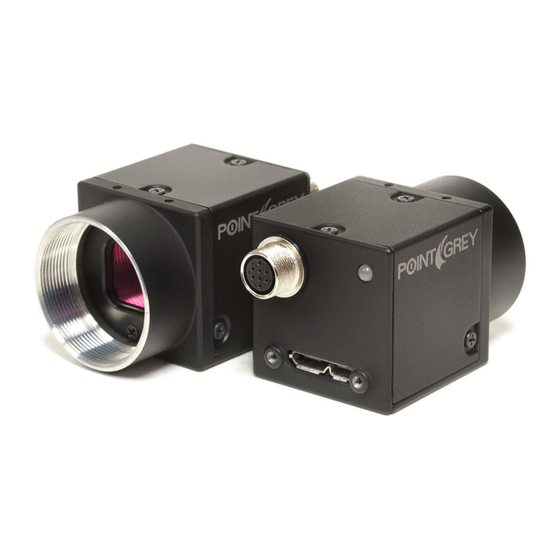
Point Grey Flea3 GigE Technical Reference 4 Flea3 GigE Physical Interface Flea3 GigE Physical Interface Flea3 GigE Physical Description 5. Status LED 1. Lens holder (C-mount) Status Indicator LED Lens Mounting 6. GigE connector 2. Glass/IR filter system Ethernet Connector. -
Page 30: Flea3 Gige Dimensions
Point Grey Flea3 GigE Technical Reference 4 Flea3 GigE Physical Interface Flea3 GigE Dimensions Figure 4.1: Flea3 GigE Dimensional Diagram To obtain 3D models, contact support@ptgrey.com. Mounting with the Case or Mounting Bracket Using the Case The case is equipped with the following mounting holes: Two (2) M2 x 2mm mounting holes on the top of the case Three (3) M3 x 2.5mm mounting holes on the bottom of the case... -
Page 31: Tripod Adapter Dimensions
Point Grey Flea3 GigE Technical Reference 4 Flea3 GigE Physical Interface 4.3.1 Tripod Adapter Dimensions Figure 4.2: Tripod Adapter Dimensional Diagram Revised 10/29/2013 Copyright ©2010-2013 Point Grey Research Inc. -
Page 32: Lens Mounting
Point Grey Flea3 GigE Technical Reference 4 Flea3 GigE Physical Interface Lens Mounting Lenses are not included with individual cameras. Related Knowledge Base Articles Title Article Selecting a lens for your camera Knowledge Base Article 345 The lens mount is compatible with C-mount lenses. Correct focus cannot be achieved using a CS-mount lens on a C- mount camera. -
Page 33: Dust Protection
Point Grey Flea3 GigE Technical Reference 4 Flea3 GigE Physical Interface Dust Protection The camera housing is designed to prevent dust from falling directly onto the sensor's protective glass surface. This is achieved by placing a piece of clear glass (monochrome camera models) or an IR cut-off filter (color models) that sits above the surface of the sensor's glass. -
Page 34: Infrared Cut-Off Filters
Infrared Cut-Off Filters Point Grey color camera models are equipped with an additional infrared (IR) cut-off filter. This filter can reduce sensitivity in the near infrared spectrum and help prevent smearing. The properties of this filter are illustrated in the results below. -
Page 35: Camera Interface And Connectors
Category 5e or 6 cables up to 100 meters in length should be used for connecting the camera to the network interface card on the host system. Point Grey sells a 5-meter Category 5e cable for this purpose. To purchase a recommended cable from Point Grey, visit the... - Page 36 Point Grey Flea3 GigE Technical Reference 4 Flea3 GigE Physical Interface For details on GPIO circuits, see GPIO Electrical Characteristics. Revised 10/29/2013 Copyright ©2010-2013 Point Grey Research Inc.
-
Page 37: General Flea3 Gige Operation
Control. The required input voltage is 12 - 24 V DC. Point Grey sells a 12 V wall-mount power supply equipped with a HR25 8-pin GPIO wiring harness for connecting to the camera. For more information, see the miscellaneous product accessories page on the Point Grey website. -
Page 38: Genicam User Set Control
Point Grey Flea3 GigE Technical Reference 5 General Flea3 GigE Operation 5.2.1 GenICam User Set Control Name Display Name Description Value 0 (default) Indicates the user set that is currently in use. At initialization time, the CurrentUserSet Current User Set... -
Page 39: Non-Volatile Flash Memory
Firmware is programming that is inserted into the programmable read-only memory (programmable ROM) of most Point Grey cameras. Firmware is created and tested like software. When ready, it can be distributed like other software and installed in the programmable read-only memory by the user. -
Page 40: Determining Firmware Version
Point Grey Flea3 GigE Technical Reference 5 General Flea3 GigE Operation 5.5.1 Determining Firmware Version To determine the firmware version number of your camera: In FlyCapture, open the Camera Control dialog and click on Camera Information. If you're implementing your own code, use flycaptureGetCameraRegister(). -
Page 41: Input/Output Control
Point Grey Flea3 GigE Technical Reference 6 Input/Output Control Input/Output Control General Purpose Input/Output (GPIO) The camera has an 8-pin GPIO connector on the back of the case; refer to the diagram below for wire color-coding. The connector is a Hirose HR25 8 pin connector with part number: HR25-7TR-8SA. The male connector is part number: HR25-7TP-8P. -
Page 42: Gpio Modes
Point Grey Flea3 GigE Technical Reference 6 Input/Output Control GPIO Modes 6.2.1 GPIO Mode 0: Input When a GPIO pin is put into GPIO Mode 0 it is configured to accept external trigger signals. See Serial Communication. 6.2.2 GPIO Mode 1: Output When a GPIO pin is put into GPIO Mode 1 it is configured to send output signals. -
Page 43: Genicam Digital Input/Output Control
Point Grey Flea3 GigE Technical Reference 6 Input/Output Control GenICam Digital Input/Output Control Name Display Name Description Value Line 0 Selects the physical line (or GPIO pin) of the Line 1 LineSelector + Line Selector external device connector to configure. -
Page 44: Programmable Strobe Output
Point Grey Flea3 GigE Technical Reference 6 Input/Output Control Programmable Strobe Output The camera is capable of outputting a strobe pulse off select GPIO pins that are configured as outputs. The start of the strobe can be offset from either the start of exposure (free-running mode) or time of incoming trigger (external trigger mode). -
Page 45: Serial Communication
Debouncer By default, Point Grey cameras will reject a trigger signal that has a pulse width of less than 16 ticks of the pixel clock. With the debouncer the user can define a debounce value. Once the debouncer is enabled and defined, the camera will reject a trigger signal with a pulse width less than the defined debounce value. - Page 46 Point Grey Flea3 GigE Technical Reference 6 Input/Output Control Figure 6.1: Debouncer Filtering Invalid Signals To set the debouncer: GenICam—Digital Input Output Control Revised 10/29/2013 Copyright ©2010-2013 Point Grey Research Inc.
-
Page 47: Gpio Electrical Characteristics
Point Grey Flea3 GigE Technical Reference 6 Input/Output Control GPIO Electrical Characteristics Both the opto-isolated input and output have over current protection. The output is open collector and thus requires a pull-up resistor to operate. The rise time and bias current will be determined by the resistor value chosen. - Page 48 Point Grey Flea3 GigE Technical Reference 6 Input/Output Control Note: identical for IO3 pin 4 Figure 6.4: Input/output circuit Revised 10/29/2013 Copyright ©2010-2013 Point Grey Research Inc.
-
Page 49: Image Acquisition
Point Grey Flea3 GigE Technical Reference 7 Image Acquisition Image Acquisition Asynchronous Triggering The camera supports asynchronous triggering, which allows the start of exposure (shutter) to be initiated by an external electrical source (or hardware trigger) or from an internal software mechanism (software trigger). - Page 50 Point Grey Flea3 GigE Technical Reference 7 Image Acquisition Name Display Name Description Value Controls the mode for automatic FrameRateAuto Frame Rate Auto frame rate adjustment Continuous Selects the type of trigger to Exposure Start/ TriggerSelector Trigger Selector configure. Derived from Exposure Exposure Active Mode.
-
Page 51: Standard External Trigger (Mode 0)
Point Grey Flea3 GigE Technical Reference 7 Image Acquisition 7.1.2 Standard External Trigger (Mode 0) Trigger Mode 0 is best described as the standard external trigger mode. When the camera is put into Trigger Mode 0, the camera starts integration of the incoming light from external trigger input falling/rising edge. The Exposure Time describes integration time. -
Page 52: Bulb Shutter Trigger (Mode 1)
Point Grey Flea3 GigE Technical Reference 7 Image Acquisition 7.1.3 Bulb Shutter Trigger (Mode 1) Also known as Bulb Shutter mode, the camera starts integration of the incoming light from external trigger input. Integration time is equal to low state time of the external trigger input. -
Page 53: Skip Frames Trigger (Mode 3)
Point Grey Flea3 GigE Technical Reference 7 Image Acquisition 7.1.4 Skip Frames Trigger (Mode 3) Trigger Mode 3 allows the user to put the camera into a mode where the camera only transmits one out of N specified images. This is an internal trigger mode that requires no external interaction. Where N is the parameter set in the Trigger Mode, the camera will issue a trigger internally at a cycle time that is N times greater than the current frame rate. ... -
Page 54: Multiple Exposure Preset Trigger (Mode 4)
Point Grey Flea3 GigE Technical Reference 7 Image Acquisition 7.1.5 Multiple Exposure Preset Trigger (Mode 4) Trigger Mode 4 allows the user to set the number of triggered images to be exposed before the image readout starts. In the case of Trigger Mode 4, the shutter time is controlled by the Shutter value; the minimum resolution of the duration is therefore limited by the shutter resolution. -
Page 55: Multiple Exposure Pulse Width Trigger (Mode 5)
Point Grey Flea3 GigE Technical Reference 7 Image Acquisition 7.1.6 Multiple Exposure Pulse Width Trigger (Mode 5) Trigger Mode 5 allows the user to set the number of triggered images to be exposed before the image readout starts. In the case of Trigger Mode 5, the shutter time is controlled by the trigger pulse duration; the minimum resolution of the... -
Page 56: Low Smear Trigger (Mode 13)
Point Grey Flea3 GigE Technical Reference 7 Image Acquisition 7.1.7 Low Smear Trigger (Mode 13) Trigger Mode 13 is a reduced smear imaging mode. This mode is available for: FL3-GE-13S2 FL3-GE-28S4 Smear reduction works by increasing the speed of the vertical clock near the end of the integration cycle. This step is also known as fast dump. -
Page 57: Overlapped Exposure Readout Trigger (Mode 14)
Point Grey Flea3 GigE Technical Reference 7 Image Acquisition 7.1.8 Overlapped Exposure Readout Trigger (Mode 14) Trigger Mode 14 is a vendor-unique trigger mode that is very similar to Trigger Mode 0, but allows for triggering at faster frame rates. This mode works well for users who want to drive exposure start with an external event. However, users who need a precise exposure start should use Trigger Mode 0. -
Page 58: Multi-Shot Trigger (Mode 15)
Point Grey Flea3 GigE Technical Reference 7 Image Acquisition 7.1.9 Multi-Shot Trigger (Mode 15) Trigger Mode 15 is a vendor-unique trigger mode that allows the user to fire a single hardware or software trigger and have the camera acquire and stream a predetermined number of images at the current frame rate. -
Page 59: External Trigger Timing
Point Grey Flea3 GigE Technical Reference 7 Image Acquisition External Trigger Timing The time from the external trigger firing to the start of shutter is shown below: 1. Trigger Pulse 2. Propagation Delay 3. Exposure Time 4. Sensor Readout 5. Data Transfer Figure 7.9: External trigger timing characteristics... -
Page 60: Changing Video Modes While Triggering
Point Grey Flea3 GigE Technical Reference 7 Image Acquisition Changing Video Modes While Triggering You can change the video format and mode of the camera while operating in trigger mode. Whether the new mode that is requested takes effect in the next triggered image depends on the timing of the request and the trigger mode in effect. -
Page 61: Asynchronous Software Triggering
Point Grey Flea3 GigE Technical Reference 7 Image Acquisition Asynchronous Software Triggering Shutter integration can be initiated by a software trigger by setting the Trigger Source to Software in the GenICam features. The time from a software trigger initiation to the start of shutter is shown below: 1. -
Page 62: Flea3 Gige Attributes
Point Grey Flea3 GigE Technical Reference 8 Flea3 GigE Attributes Flea3 GigE Attributes Pixel Formats Pixel formats are an encoding scheme by which color or monochrome images are produced from raw image data. Most pixel formats are numbered 8, 12, or 16 to represent the number of bits per pixel. - Page 63 Point Grey Flea3 GigE Technical Reference 8 Flea3 GigE Attributes YUV411 is considered a low resolution format which transmits 12 bits per pixel. Each Y value has 8 bits, but the U and V values are shared between 4 pixels. The reduces bandwidth by one half compared to YUV444, but also reduces the color information being recorded.
-
Page 64: Video Modes Overview
Modes that perform binning may increase image intensity. On Point Grey cameras, binning refers to the aggregation of pixels. Analog binning is aggregation that occurs before the analog to digital conversion. Digital binning is aggregation that occurs after the analog to digital conversion. Unless specified otherwise, color data is maintained in binning modes. -
Page 65: Video Mode Descriptions
Point Grey Flea3 GigE Technical Reference 8 Flea3 GigE Attributes 8.2.1 Video Mode Descriptions Brightness Mode Models Description Frame Rate Increase Increase ROI No Binning 2X/2X Additive Binning All Color Models 2X/2X Subsampling FL3-GE-20S4C/M Yes for Mono FL3-GE-28S4C/M 4X/4X Additive Binning... - Page 66 Point Grey Flea3 GigE Technical Reference 8 Flea3 GigE Attributes is performed after color processing. Although image quality may be poorer than in Mode 5, a frame rate increase is possible in this mode. Mode 7 Mode 7 allows only for specifying a region of interest, and does not perform any binning. This mode uses a slower pixel clock, and is recommended for longer extended shutter times and/or improved imaging performance.
-
Page 67: Genicam Image Format Control
Point Grey Flea3 GigE Technical Reference 8 Flea3 GigE Attributes GenICam Image Format Control Name Display Name Description Value SensorWidth Sensor Width Effective width of the sensor in pixels SensorHeight Sensor Height Effective height of the sensor in pixels MaxWidth... -
Page 68: Frame Rates
Point Grey Flea3 GigE Technical Reference 8 Flea3 GigE Attributes Frame Rates The tables on the following pages show the supported pixel formats and mode combinations, along with achievable frame rates at varying resolutions, for each camera model. In some cases, enabling Jumbo Frames on the NIC can help to achieve maximum frame rates. Jumbo Frames can be enabled using the GigE Configurator. -
Page 69: Fl3-Ge-03S2 Video Modes And Frame Rates
Point Grey Flea3 GigE Technical Reference 8 Flea3 GigE Attributes 8.4.2 FL3-GE-03S2 Video Modes and Frame Rates Table 8.1: FL3-GE-03S2M Frame Rates Mode 0 Pixel Format 648 x 488 640 x 480 320 x 240 160 x 120 8-, 12-bit (Mono) -
Page 70: Fl3-Ge-08S2 Video Modes And Frame Rates
Point Grey Flea3 GigE Technical Reference 8 Flea3 GigE Attributes 8.4.3 FL3-GE-08S2 Video Modes and Frame Rates Table 8.3: FL3-GE-08S2M Frame Rates Mode 0 Pixel Format 1032 x 776 640 x 480 320 x 240 160 x 120 8-, 12-bit (Mono) -
Page 71: Fl3-Ge-13S2 Video Modes And Frame Rates
Point Grey Flea3 GigE Technical Reference 8 Flea3 GigE Attributes 8.4.4 FL3-GE-13S2 Video Modes and Frame Rates Table 8.5: FL3-GE-13S2M Frame Rates Mode 0 Pixel Format 1288 x 964 1280 x 960 640 x 480 320 x 240 160 x 120... -
Page 72: Fl3-Ge-14S3 Video Modes And Frame Rates
Point Grey Flea3 GigE Technical Reference 8 Flea3 GigE Attributes 8.4.5 FL3-GE-14S3 Video Modes and Frame Rates Table 8.7: FL3-GE-14S3M Frame Rates Mode 0 Pixel Format 1384 x 1032 1280 x 960 640 x 480 320 x 240 160 x 120... -
Page 73: Fl3-Ge-20S4 Video Modes And Frame Rates
Point Grey Flea3 GigE Technical Reference 8 Flea3 GigE Attributes 8.4.6 FL3-GE-20S4 Video Modes and Frame Rates Table 8.9: FL3-GE-20S4M Frame Rates Mode 0 Pixel Format 1624 x 1224 1600 x 1200 1280 x 960 640 x 480 320 x 240... - Page 74 Point Grey Flea3 GigE Technical Reference 8 Flea3 GigE Attributes Mode 6 Pixel Format 404 x 306 320 x 240 160 x 120 All Formats Mode 7 Pixel Format 1624 x 1224 1600 x 1200 1280 x 960 640 x 480...
-
Page 75: Fl3-Ge-28S4 Video Modes And Frame Rates
Point Grey Flea3 GigE Technical Reference 8 Flea3 GigE Attributes 8.4.7 FL3-GE-28S4 Video Modes and Frame Rates Table 8.11: FL3-GE-28S4M Frame Rates Mode 0 Pixel Format 1928 x 1448 1600 x 1200 1280 x 960 640 x 480 320 x 240... - Page 76 Point Grey Flea3 GigE Technical Reference 8 Flea3 GigE Attributes Mode 6 Pixel Format 480 x 362 320 x 240 160 x 120 All Formats Mode 7 Pixel Format 1928 x 1448 1600 x 1200 1280 x 960 640 x 480...
-
Page 77: Fl3-Ge-50S5 Video Modes And Frame Rates
Point Grey Flea3 GigE Technical Reference 8 Flea3 GigE Attributes 8.4.8 FL3-GE-50S5 Video Modes and Frame Rates Table 8.13: FL3-GE-50S5M Frame Rates Mode 0 Pixel Format 2448 x 2048 1600 x 1200 1280 x 960 640 x 480 320 x 240... - Page 78 Point Grey Flea3 GigE Technical Reference 8 Flea3 GigE Attributes Mode 6 Pixel Format 612 x 512 320 x 240 160 x 120 All Formats Mode 7 2448 x 1600 x Pixel Format 1280 x 960 640 x 480 320 x 240...
-
Page 79: Shutter Type
Point Grey Flea3 GigE Technical Reference 8 Flea3 GigE Attributes Shutter Type 8.5.1 Global Shutter For cameras with a global shutter sensor, for each frame all of the lines start and stop exposure at the same time. The exposure time for each line is the same. Following exposure, data readout begins. The readout time for each line is the same but the start and end times are staggered. -
Page 80: Overview Of Imaging Parameters
Point Grey Flea3 GigE Technical Reference 8 Flea3 GigE Attributes Overview of Imaging Parameters The camera supports control over the following imaging parameters: Imaging Parameter GenICam Feature FlyCapture API Sample Code Brightness Analog Control Setting Brightness Using the FlyCapture API... -
Page 81: Genicam Analog Control
Point Grey Flea3 GigE Technical Reference 8 Flea3 GigE Attributes GenICam Analog Control Name Display Name Description Value Gain Gain (dB) Gain applied to the image in dB GainAuto Gain Auto Controls the mode for automatic gain adjustment Once Continuous... -
Page 82: Brightness
Shutter Time The Flea3 GigE supports Automatic, Manual, and One Push control of the image sensor shutter time. Shutter times are scaled by the divider of the basic frame rate. For example, dividing the frame rate by two (e.g. 15 FPS to 7.5 FPS) causes the maximum shutter time to double (e.g. -
Page 83: Gain
The Flea3 GigE supports Automatic and One Push gain modes. The A/D converter provides a PxGA gain stage (white balance/preamp) and VGA gain stage. The main VGA gain stage is available to the user, and is variable between models per the table below. -
Page 84: Auto Exposure
Point Grey Flea3 GigE Technical Reference 8 Flea3 GigE Attributes Model Range FL3-GE-13S2C-C 0 dB to 24 dB FL3-GE-14S3M-C 0 dB to 24 dB FL3-GE-14S3C-C 0 dB to 24 dB FL3-GE-20S4M-C 0 dB to 24 dB FL3-GE-20S4C-C 0 dB to 24 dB... -
Page 85: Sharpness
8.12 Sharpness The Flea3 GigE supports sharpness adjustment, which refers to the filtering of an image to reduce blurring at image edges. Sharpness is implemented as an average upon a 3x3 block of pixels, and is only applied to the green component of the Bayer tiled pattern. - Page 86 Point Grey Flea3 GigE Technical Reference 8 Flea3 GigE Attributes When Gamma is turned on, Lookup Table is turned off. When Lookup Table is turned on, Gamma is turned off. Alternatively, the camera has a 9-bit input lookup table that produces a 9-bit output. The LUT has two banks that the user can select between.
-
Page 87: High Dynamic Range (Hdr) Imaging
Point Grey Flea3 GigE Technical Reference 8 Flea3 GigE Attributes To adjust gamma: GenICam—Analog Control FlyCapture API—Setting Gamma Using the FlyCapture API 8.14 High Dynamic Range (HDR) Imaging Generally speaking, digital camera systems are not capable of accurately capturing many of the high dynamic range scenes that they are exposed to in real world settings. - Page 88 Point Grey Flea3 GigE Technical Reference 8 Flea3 GigE Attributes The following frame-specific information can be provided: Timestamp Gain Shutter Brightness White Balance Frame counter Strobe Pattern counter GPIO pin state ROI position If you turned on all possible options the first 40 bytes of image data would contain camera information in the following format, when accessed using the FlyCapture 2 API: (assuming unsigned char* data = rawImage.GetData();...
-
Page 89: White Balance
White balance is applicable to color models only. The Flea3 GigE supports white balance adjustment, which is a system of color correction to account for differing lighting conditions. Adjusting white balance by modifying the relative gain of R, G and B in an image enables white areas to look "whiter". -
Page 90: Bayer Color Processing
Point Grey Flea3 GigE Technical Reference 8 Flea3 GigE Attributes The term Continuous is the same as Auto and the term Once is the same as One Push. To adjust white balance: GenICam—Analog Control FlyCapture API—Setting White Balance Using the FlyCapture API 8.18 Bayer Color Processing... -
Page 91: Hue
8.19 Hue Hue is applicable to color models only. This provides a mechanism to control the Hue component of the images being produced by the Flea3 GigE, given a standard Hue, Saturation, Value (HSV) color space. To adjust hue use: GenICam—Analog Control... -
Page 92: Troubleshooting
Point Grey Flea3 GigE Technical Reference 9 Troubleshooting Troubleshooting Support Point Grey Research endeavors to provide the highest level of technical support possible to our customers. Most support resources can be accessed through the Point Grey Product Support page. Creating a Customer Login Account The first step in accessing our technical support resources is to obtain a Customer Login Account. -
Page 93: Camera Diagnostics
Point Grey Flea3 GigE Technical Reference 9 Troubleshooting Camera Diagnostics Use the following parameters to monitor the error status of the camera and troubleshoot problems: Time from Initialize—This reports the time, in seconds, since the camera was initialized during a hard power-up. This is different from powering up the camera, which will not reset this time. -
Page 94: Status Indicator Led
Point Grey Flea3 GigE Technical Reference 9 Troubleshooting Status Indicator LED The user can turn off the camera’s status LED. LEDs are re-enabled the next time the camera is power cycled. LED Status Description Not receiving power Steady green, high intensity (~5 seconds) 1. -
Page 95: Channel Balancing
Figure 9.2: Example of dual channel image with no balancing To address this issue, Point Grey "balances" every multiple tap unit as part of the quality control process. This balancing process attempts to minimize the difference in gains that result from the different A/D converters. -
Page 96: Blemish Pixel Artifacts
Pixel Defect Correction Point Grey tests for blemish pixels on each camera. The mechanism to correct blemish pixels is hard-coded into the camera firmware, and can be turned off and on by the user . Pixel correction is on by default. The correction algorithm involves applying the average color or grayscale values of neighboring pixels to the blemish pixel. -
Page 97: Vertical Smear Artifact
Point Grey Flea3 GigE Technical Reference 9 Troubleshooting Vertical Smear Artifact When a strong light source is shone on the camera, a faint bright line may be seen extending vertically through an image from a light-saturated spot. Vertical smear is a byproduct of the interline transfer system that extracts data from the CCD. -
Page 98: A Flycapture Api Code Samples
Point Grey Flea3 GigE Technical Reference A FlyCapture API Code Samples FlyCapture API Code Samples Setting a GPIO Pin to Strobe Using the FlyCapture API The following FlyCapture code sample uses the C++ interface to do the following: Configures GPIO1 as the strobe output pin. -
Page 99: Setting Brightness Using The Flycapture Api
Point Grey Flea3 GigE Technical Reference A FlyCapture API Code Samples Setting Brightness Using the FlyCapture API The following FlyCapture code snippet adjusts brightness to 0.5% using the C++ interface. The snippet assumes a Camera object cam. //Declare a Property struct. -
Page 100: Setting Auto Exposure Using The Flycapture Api
Point Grey Flea3 GigE Technical Reference A FlyCapture API Code Samples error = cam.SetProperty( &prop ); Setting Auto Exposure Using the FlyCapture API The following FlyCapture code snippet adjusts auto exposure to -3.5 EV using the C++ interface. The snippet assumes a Camera object cam. -
Page 101: Setting White Balance Using The Flycapture Api
Point Grey Flea3 GigE Technical Reference A FlyCapture API Code Samples //Set the absolute value of gamma to 1.5 prop.absValue = 1.5; //Set the property. error = cam.SetProperty( &prop ); A.10 Setting White Balance Using the FlyCapture API The following FlyCapture code snippet adjusts the white balance red channel to 500 and the blue channel to 850 using the C++ interface. -
Page 102: Setting Saturation Using The Flycapture Api
Point Grey Flea3 GigE Technical Reference A FlyCapture API Code Samples prop.absControl = true; //Set the absolute value of hue to -30 deg. prop.absValue = -30; //Set the property. error = cam.SetProperty( &prop ); A.13 Setting Saturation Using the FlyCapture API The following FlyCapture code snippet adjusts saturation to 200% using the C++ interface. -
Page 103: B Flycapture Sdk Examples
Point Grey Flea3 GigE Technical Reference B FlyCapture SDK Examples FlyCapture SDK Examples The FlyCapture SDK includes a number of examples in C, C++, C#, and VB.NET to help get you started in some basic camera programming tasks. The full example source code can be found in the \src directory of the FlyCapture2 SDK installation. To access the examples workspace from the Start menu, select Program Files>FlyCapture2 SDK >Examples... -
Page 104: Extendedshutterex
The ExtendedShutterEx example program demonstrates how to enable and calculate extended integration times for your camera. The way this is done can differ between cameras. Many applications require extended shutter (integration) times up to several seconds long. Most Point Grey Imaging Products implement extended shutter functionality in one of two ways: 1. -
Page 105: Flycap2Mfc
The FlyCap2MFC example is the equivalent of the FlyCap2 example program, except it uses the Microsoft Foundation Class Library to implement the graphical user interface. Like FlyCap2, it is the main Point Grey Research application used to work with single lens cameras. It allows a user to select a camera to start, and then starts streaming the images to screen. -
Page 106: Gigegrabex
Point Grey Flea3 GigE Technical Reference B FlyCapture SDK Examples Available for: VB.NET B.11 GigEGrabEx The GigEGrabEx example program demonstrates how to use the GigECamera object to set up a GigE Vision specific Image grabbing loop. Available for: VB.NET B.12 GrabCallbackEx The GrabCallbackEx example program demonstrates how to set up an asynchronous image callback application using FlyCapture2 API. - Page 107 If the camera has already been started with the chosen bytes per packet, this value can be queried from the format 7 registers. See the entry for PACKET_PER_FRAME_INQ (0x048) in the Point Grey Digital Camera Register Reference. Partial image event notification operates differently between the Windows and Linux operating...
-
Page 108: Multiplecameraex
Point Grey Flea3 GigE Technical Reference B FlyCapture SDK Examples B.15 MultipleCameraEx This example starts multiple cameras using the StartSyncCapture() function. This function synchronizes image grabbing across all cameras. Additionally, it enables timestamps to be embedded in images, allowing users to obtain the exact timing of each camera's exposure. -
Page 109: Serialportex
Point Grey Flea3 GigE Technical Reference B FlyCapture SDK Examples Once the image is stored in the camera, the image can be recovered at any time on any PC. The example uses a FlashMode enumeration to capture the image (-c) or save the stored image to disk (-r). ... -
Page 110: C Genicam Features
Point Grey Flea3 GigE Technical Reference C GenICam Features GenICam Features The following features are included in the XML device description file on the camera to control, monitor, and query the camera operation. Not all operations can be controlled using the XML file; those not included are controlled via CSRs. -
Page 111: Image Format Control
Point Grey Flea3 GigE Technical Reference C GenICam Features Name Display Name Description Value Black Level Auto Controls the mode for automatic black level adjustment Once Continuous Balance Ratio BalanceRatioSelector Selects which balance ratio to control (for White Balance) Selector... -
Page 112: Acquisition Control
Point Grey Flea3 GigE Technical Reference C GenICam Features Name Display Name Description Value Flip horizontally the image sent by the device. The AOI is applied True ReverseX Reverse X after the flip False Mono8, Mono12, Mono16, Raw8, PixelFormat Pixel Format... -
Page 113: Digital Input Output Control
Point Grey Flea3 GigE Technical Reference C GenICam Features Name Display Name Description Value Acquisition Frame Rate Enables manual control of the True AcquisitionFrameRateControlEnabled Control Enabled camera frame rate False Controls the mode for automatic FrameRateAuto Frame Rate Auto frame rate adjustment... -
Page 114: Transport Layer Control
Point Grey Flea3 GigE Technical Reference C GenICam Features Name Display Name Description Value Controls the invertion of the signal of the selected True LineInverter Line Inverter input or output line False True StrobeEnabled Strobe Enabled Enables/disables strobe False True = High... - Page 115 Point Grey Flea3 GigE Technical Reference C GenICam Features Name Display Name Description Value Indicates if Persistent IP GEV Current configuration scheme is True GevCurrentIPConfigurationPersistentIP IPConfiguration Persistent activated on the given network False interface Current IP address for the given GevCurrentIPAddress...
- Page 116 Point Grey Flea3 GigE Technical Reference C GenICam Features Name Display Name Description Value User Defined Name Serial Number Heartbeat Disable Link Speed CCP Application Socket Manifest Table Test Data Discovery Ack Delay Discovery Ack Delay Writable Extended Status Codes Action...
- Page 117 Point Grey Flea3 GigE Technical Reference C GenICam Features Name Display Name Description Value GEV Stream Channel Selects the stream channel to GevStreamChannelSelector Selector control GevSCPInterfaceIndex GEV SCP Interface Index Index of network interface to use GevSCPHostPort GEV SCP Host Port...
-
Page 118: User Set Control
Point Grey Flea3 GigE Technical Reference C GenICam Features User Set Control Name Display Name Description Value 0 (default) Indicates the user set that is currently in use. At initialization time, the CurrentUserSet Current User Set camera loads the most recently saved user set... -
Page 119: D Gige Vision Bootstrap Registers
Point Grey Flea3 GigE Technical Reference D GigE Vision Bootstrap Registers GigE Vision Bootstrap Registers The camera supports the following GigE Vision bootstrap registers. All registers are implemented according to the GigE Vision Standard version 1.2, available for download at visiononline.org. - Page 120 Point Grey Flea3 GigE Technical Reference D GigE Vision Bootstrap Registers Address Name Type Length (no offset) 0A00h Control Channel Privilege Read/Write 0D00h + 40h * x Stream Channel Port Read/Write with 0 <= x < 512 0D04h + 40h * x...
-
Page 121: E Control And Status Registers
Point Grey Flea3 GigE Technical Reference E Control and Status Registers Control and Status Registers Some features of the Flea3 GigE are accessible only using control and status registers (CSRs) that conform to the IICD 1.32 standard. These include the following: Frame Buffer—IMAGE_RETRANSMIT: 634h... -
Page 122: Data_Flash_Ctrl: 1240H
Point Grey Flea3 GigE Technical Reference E Control and Status Registers Format: Field Description Image Buffer On/Off Control Image_Buffer_Ctrl 0: OFF, 1: ON Transfer data path Transfer_Data_Select 0: Live data, 1: Buffered image data Ignored if ISO_EN=1 [2-7] Reserved Maximum number of images that can be stored in the current video format. Must... -
Page 123: Gpio_Ctrl_Pin: 1110H-1140H
Point Grey Flea3 GigE Technical Reference E Control and Status Registers GPIO_CTRL_PIN: 1110h-1140h These registers provide control over the GPIO pins. Register GPIO_CTRL_PIN_0 1110h GPIO_CTRL_PIN_1 1120h GPIO_CTRL_PIN_2 1130h GPIO_CTRL_PIN_3 1140h Format: Field Description Presence of this feature Presence_Inq 0: Not Available, 1: Available... -
Page 124: Gpio_Xtra_Pin: 1114H-1144H
Point Grey Flea3 GigE Technical Reference E Control and Status Registers GPIO_XTRA_PIN: 1114h-1144h These registers contain mode specific data for the GPIO pins. Units are ticks of a 1.024MHz clock. Register GPIO_XTRA_PIN_0 1114h GPIO_XTRA_PIN_1 1124h GPIO_XTRA_PIN_2 1134h GPIO_XTRA_PIN_3 1144h Format:... -
Page 125: Pixel_Clock_Freq: 1Af0H
Point Grey Flea3 GigE Technical Reference E Control and Status Registers Field Description Trigger mode (Trigger_Mode_0..15): used to set the trigger mode to be used. For more information, see Asynchronous Triggering. Trigger_Mode [12-15] Query the Trigger_Mode_Inq fields of the TRIGGER_INQ register for available trigger modes. -
Page 126: Lut: 80000H - 80048H
Point Grey Flea3 GigE Technical Reference E Control and Status Registers LUT: 80000h – 80048h Offset Name Field Description Presence of this feature Presence_Inq 0: Not Available, 1: Available [1-4] Reserved ON_OFF_Inq Capability of turning this feature ON or OFF. - Page 127 Point Grey Flea3 GigE Technical Reference E Control and Status Registers Offset Name Field Description Write_Bank_0_Inq [16] Capability of writing data to Bank 0 Write_Bank_1_Inq [17] Capability of writing data to Bank 1 Write_Bank_2_Inq [18] Capability of writing data to Bank 2...
-
Page 128: Frame_Info: 12F8H
Point Grey Flea3 GigE Technical Reference E Control and Status Registers Offset Name Field Description Bank_7_ 80028h Bank_7_Quadlet_Offset [0-31] 32-bit offset of Bank 7 table data Offset_Inq Bank_8_ 8002Ch Bank_8_Quadlet_Offset [0-31] 32-bit offset of Bank 8 table data Offset_Inq Bank_9_... -
Page 129: Initialize: 000H
Point Grey Flea3 GigE Technical Reference E Control and Status Registers Field Description Frame-Specific Information [22] Region of Interest (ROI) position (See page [23] GPIO Pin State [24] Strobe Pattern Counter [25] Frame Counter [26] White Balance CSR Display image-specific information... -
Page 130: Xmit_Failure: 12Fch
Point Grey Flea3 GigE Technical Reference E Control and Status Registers E.14 XMIT_FAILURE: 12FCh Format: Field Description Presence of this feature Presence_Inq 0: Not Available, 1: Available Read: Count of failed frame transmissions. Frame_Count [1-31] Write: Reset. E.15 VMODE_ERROR_STATUS: 628h... -
Page 131: Pixel_Defect_Ctrl: 1A60H
Point Grey Flea3 GigE Technical Reference E Control and Status Registers E.18 PIXEL_DEFECT_CTRL: 1A60h Format: Field Description Presence of this feature Presence_Inq 0: Not Available, 1: Available [1-5] Reserved Enable or disable FPGA pixel correction ON_OFF 0: Off, 1: On Reserved... -
Page 132: Revision History
Point Grey Flea3 GigE Technical Reference Revision History Revision History Revision Date Notes May 12, 2011 Initial version: support for model FL3-GE-13S2 August 29, 2011 Change in LED behavior during IP addressing Added models FL3-GE-03S2 and FL3-GE-08S2 November 25, 2011...
Need help?
Do you have a question about the Flea3 GigE and is the answer not in the manual?
Questions and answers