Table of Contents
Advertisement
Quick Links
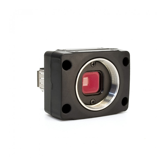
FIREFLY
®
MV SPECIFICATIONS
SPECIFICATION
FFMU-03MTM/C (BW or Color)
Image Sensor Type
Shutter Type
Global shutter (Micron TrueSNAP™)
Image Sensor Model
Maximum Resolution
Pixel Size
Analog-to-Digital Converter
Video Data Output
Image Data Formats
Y8, Y16 (monochrome), 8-bit and 16-bit raw Bayer data (color models)
Digital Interface
Transfer Rates
752x480 at 61 FPS
1
Maximum Frame Rate
320x240 at 112 FPS (ROI)
320x240 at 122 FPS (2 x 2 pixel binning)
Partial Image Modes
7-pin JST GPIO connector, 4 pins for trigger and strobe, 1 pin +3.3 V, 1 Vext pin for
General Purpose I/O Ports
Gain Control
automatic / manual, 0 dB to 12 dB
Shutter Speed
auto / manual, 0.12 ms to 512 ms
Gamma
Synchronization
External Trigger Modes
Power Requirements
4.745 to 5.25 V via the Mini-B USB 2.0 or GPIO connector, less than one (1) Watt
Dimensions (L x W x H)
Mass
Camera Specifi cations
Memory Storage
three memory channels for user confi gurable power-up settings
Lens Mount
CS-mount (5mm C-mount adapter included) • M12 microlense mount
Compliance
Operating Temperature
Storage Temperature
1
Using standard non-Format_7 video formats and modes
CAMERA AND DEVICE CONTROL
Memory Channels
Non-volatile storage of camera default power-up settings
Strobe Output
Strobe output with confi gurable delay and duration
Absolute Value Controls
Shutter and gain reported in real-world units (seconds and dB)
Broadcast Properties
Camera responds to broadcast register writes on the same bus
Camera Upgrades
Firmware upgradeable in fi eld via IEEE-1394 interface.
IMAGE PROCESSING
ADC On-Chip
10-bit linear or 12-bit to 10-bit companding mode via Gamma
Image Flip
Horizontal image fl ipping (mirror image)
Embedded Image Info
Pixels contain image timestamp (1394 cycle time)
IMAGE ACQUISITION
3
Global Shutter
Photodiode pixels with simultaneous integration and readout
Near-IR Performance
3
Enhanced performance provides NIR QE greater than 35%
Auto Exposure Control
Ensures optimal auto settings of shutter and gain for each image
Fast Frame Rates
Faster standard frame rates up to 60 FPS
Partial Image Modes
Format_7 modes for fast frame rates and higher signal-to-noise
Multiple Trigger Modes
Standard external trigger mode, skip frames mode
Gain and Brightness
Adjust gain and black clamp via a 10-bit A/D converter
3
FMVU-03MTM/C only
CAMERA INTERFACE
USB 2.0 CONNECTOR
Firefl y
®
MV
The
has a standard USB 2.0 connector that is used for data transmission, camera control and
powering the camera.
CABLES
The maximum USB 2.0 cable length between any USB node (e.g. camera to PCI card, card to hub, etc.) is 5.0 m, as
specifi ed by the USB 2.0 standard. Use standard, shielded twisted pair copper cables.
GENERAL PURPOSE I/O CONNECTOR
The Firefl y MV has a 7-pin GPIO connector on the back of the board. The connector is made by JST (Mfg P/N:
BM07B-SRSS-TB). The Development Kit contents include a pre-wired female connector; refer to the diagram
below for wire color-coding. Additional female connectors (Mfg P/N: SHR-07V-S-B) can be purchased from Digikey
(P/N: 455-1382-ND).
Diagram
Pin
1
2
7 6 5 4 3 2 1
3
4
5,
6
7
To confi gure the GPIO pins, consult the "General Purpose Input / Output"
Pre-wired GPIO cable
section of the PGR IEEE-1394 Digital Camera Register Reference.
The Firefl y MV GPIO pins are TTL 3.3V pins. Inputs can be confi gured to accept external trigger signals. When
confi gured as inputs, the pins are internally pulled high using weak pull-up resistors to allow easy triggering of the
camera by simply shorting the pin to ground (GND). Inputs can also be directly driven from a 3.3V or 5V logic
output. The inputs are protected from both over and under voltage. It is recommended, however, that they only be
connected to 5V or 3.3V digital logic signals. Outputs can be confi gured to send an output signal or strobe pulse.
When confi gured as outputs, each line can sink 10mA of current.
FMVU-13S2C (Color)
1/3" progressive scan CMOS
Rolling shutter
Micron MT9V022
Sony IMX035LQR-C
752 (H) x 480 (V)
1328 (H) x 1048 (V)
6.0 μm x 6.0 μm
3.63 μm x 3.63 μm
On-chip 10-bit ADC
On-chip 10 / 12-bit ADC
8 and 16-bit digital data
5-pin Mini-B USB 2.0 for camera control, video data, power
480 Mb/s
1328x1048 at 23FPS
664x524 at 60 FPS (2x2 pixel binning)
640x480 at 60 FPS (center cut-out mode)
pixel binning and region of interest modes via Format_7
external power
automatic / manual, 0 dB to 24 dB
auto / manual, 0.12 ms to 8000 ms
0 to 1 (enables 12-bit to 10-bit companding)
via external trigger or software trigger,
IIDC v1.31 Trigger Modes 0 and 3
24.4 x 44 x 34 mm
37 g (including tripod adapter)
IIDC 1394-based Digital Camera Specifi cation v1.31
CE, FCC Class B, RoHS
0° to 45°C
-30° to 60°C
Function
Description
Vext
Power camera externally
+3.3V
Power external circuitry up to a total of 150mA
IO0
Input / Output (Default Trigger_Src)
IO1
Input / Output
IO2
Input / Output / RS232 Transmit (TX)
IO3
Input / Output / RS232 Receive (RX)
GND
Getting Started
Firefl y
The following items are included with your Firefl y MV
Development Accessory Kit
• 2 meter USB 2.0 cable (Type A to Mini-B 5 pin)
• ACC-01-3002: GPIO wiring harness
• Firefl y MV Getting Started Manual
• FlyCapture
2
Sept 2009
STANDARD IMAGE FORMATS
Mode Description
640x480 Y8 (8bpp)
640x480 Y16 (16bpp)
PARTIAL IMAGE FORMATS (FORMAT_7)
FMVU-03MTM/C
Mode
Pixel Format
0
Mono8 (8bpp)
0
Mono8 (8bpp)
0
Mono8 (8bpp)
FMVU-13S2C
0
Mono8 (8bpp)
0
Mono8 (8bpp)
0
Mono8 (8bpp)
12-BIT TO 10-BIT COMPANDING
A gamma value of 0 yields a linear response; a value of 1 puts the camera into 12-bit to 10-bit mode. This
mode allows higher ADC resolution (12 bits) for low-level signals (shadow details) and lower ADC resolution
(9 bits) for high-level signals (highlight details).
STATUS LED
Steady on
Steady on and very bright
Flashing bright, then brighter
Steady or slow fl ashing on and off
SPECTRAL RESPONSE (QE)
FFMV-03MT / FMVU-03MT
®
MV
USB 2.0 Digital Camera
SDK (C/C++ API and device drivers) CD
®
Frames Per Second
1.875
3.75
7.5
15
•
•
•
•
Size
FPS
752x480
63
Region of interest (ROI)
320x240
125
Region of interest (ROI)
320x240
135
1328x1048
23
Region of interest (ROI)
664x524
60
640x480
60
Center cut-out mode
Receiving power and successful camera initialization
Acquiring / transmitting images
Camera registers being accessed (no image acquisition)
Camera fi rmware updated (requires power cycle),
or possible camera problem
30
60
•
•
•
Description
2x2 pixel binning
2x2 pixel binning
FMVU-13S2C
Advertisement
Table of Contents

Related Manuals for Point Grey Firefly MV FFMU-03MTM


Summary of Contents for Point Grey Firefly MV FFMU-03MTM
-
Page 1: Getting Started
FIREFLY ® MV SPECIFICATIONS SPECIFICATION FFMU-03MTM/C (BW or Color) FMVU-13S2C (Color) Image Sensor Type 1/3” progressive scan CMOS Shutter Type Global shutter (Micron TrueSNAP™) Rolling shutter Getting Started Image Sensor Model Micron MT9V022 Sony IMX035LQR-C Maximum Resolution 752 (H) x 480 (V) 1328 (H) x 1048 (V) Pixel Size 6.0 μm x 6.0 μm... - Page 2 • To test the camera’s image acquisition capabilities, run the FlyCap demo program. to prevent the generation of static electricity. From the Start menu, select All Programs > Point Grey Research > PGR FlyCapture > FlyCap.exe. • When handling the camera unit, avoid touching the lenses.
Need help?
Do you have a question about the Firefly MV FFMU-03MTM and is the answer not in the manual?
Questions and answers