Table of Contents
Advertisement
Quick Links
Advertisement
Table of Contents

Related Manuals for Point Grey Flea3 FL3-U3


Summary of Contents for Point Grey Flea3 FL3-U3
- Page 1 USB 3.0 Digital Camera Technical Reference Manual Version 5.2 Revised 9/27/2012 Point Grey Research Inc. ® 12051 Riverside Way • Richmond, BC • Canada • V6W 1K7 • T (604) 242-9937 • www.ptgrey.com Copyright © 2011-2012 Point Grey Research Inc. All Rights Reserved.
-
Page 2: Fcc Compliance
Two years. Should a unit fail during this period, Point Grey will, at its option, repair or replace the damaged unit. Repaired or replaced units will be covered for the remainder of the original equipment warranty period. -
Page 3: Table Of Contents
Point Grey Flea3 USB 3.0 Technical Reference Table of Contents 1 Welcome to Flea3 USB 3.0 1.1 Flea3 USB 3.0 Specifications 1.1.1 FL3-U3-13S2M (Mono) Imaging Performance 1.1.2 FL3-U3-13S2C (Color) Imaging Performance 1.1.3 FL3-U3-13Y3M (Mono) Imaging Performance 1.1.4 FL3-U3-13E4M (Mono) Imaging Performance 1.1.5 FL3-U3-13E4C (Color) Imaging Performance 1.1.6 FL3-U3-32S2M (Mono) Imaging Performance... - Page 4 Point Grey Flea3 USB 3.0 Technical Reference 2.4 Controlling the Camera 2.4.1 Using FlyCapture 2.4.2 Using Control and Status Registers 2.4.2.1 Modes 2.4.2.2 Values 2.4.2.3 Using the Inquiry Registers 2.4.2.4 Using the Absolute Value Registers 2.5 Configuring Camera Setup 2.5.1 Configuring Camera Drivers 2.5.2 Maximum Number of Cameras on a Single Bus...
- Page 5 Point Grey Flea3 USB 3.0 Technical Reference 3.6.4 FIRMWARE_BUILD_DATE: 1F64h 3.6.5 FIRMWARE_DESCRIPTION: 1F68-1F7Ch 4 Input/Output Control 4.1 General Purpose Input/Output (GPIO) 4.2 GPIO Modes 4.2.1 GPIO Mode 0: Input 4.2.2 GPIO Mode 1: Output 4.2.3 GPIO Mode 2: Asynchronous (External) Trigger 4.2.4 GPIO Mode 3: Strobe...
- Page 6 Point Grey Flea3 USB 3.0 Technical Reference 5.2.1 Raw 5.2.2 Mono 5.2.3 RGB 5.2.4 YUV 5.2.5 Y16 (16-bit Mono) Image Acquisition 5.2.5.1 DATA_DEPTH: 630h 5.2.6 Y8 or Y16 Raw Bayer Output 5.2.6.1 BAYER_MONO_CTRL: 1050h 5.3 Supported Formats, Modes and Frame Rates 5.3.1 FL3-U3-13S2 Video Modes...
- Page 7 Point Grey Flea3 USB 3.0 Technical Reference 6.4.4 Camera Behavior Between Triggers 6.4.5 Changing Video Modes While Triggering 6.4.6 Trigger Modes 6.4.6.1 Trigger Mode 0 (“Standard External Trigger Mode”) 6.4.6.2 Trigger Mode 1 (“Bulb Shutter Mode”) 6.4.6.3 Trigger Mode 15 (“Multi-Shot Trigger Mode”) 6.4.7 Example: Asynchronous Hardware Triggering (Using the Camera Registers)
- Page 8 Point Grey Flea3 USB 3.0 Technical Reference 7.8 White Balance 7.8.1 WHITE_BALANCE: 80Ch 7.8.2 Example: Setting White Balance Using the FlyCapture API 7.9 Shutter 7.9.1 Extended Shutter Times 7.9.2 SHUTTER: 81Ch 7.9.3 Example: Setting Shutter Using the FlyCapture API 7.10 Auto Exposure 7.10.1 AUTO_EXPOSURE: 804h...
- Page 9 Point Grey Flea3 USB 3.0 Technical Reference Appendix A: Control and Status Registers A.1 General Register Information A.1.1 Register Memory Map A.1.2 Config ROM A.1.2.1 Root Directory A.1.2.2 Unit Directory A.1.2.3 Unit Dependent Info A.1.3 Calculating Base Register Addresses using 32-bit Offsets A.2 Inquiry Registers...
- Page 10 Point Grey Flea3 USB 3.0 Technical Reference List of Tables Table 1.1: Temperature Sensor Specifications Table 1.2: USB 3.0 Micro-B Connector Pin Assignments Table 2.1: CSR Mode Control Descriptions Table 4.1: GPIO pin assignments (as shown looking at rear of camera) Table 5.1: FL3-U3-13S2M Custom Formats, Modes and Frame Rates...
- Page 11 Point Grey Flea3 USB 3.0 Technical Reference List of Figures Figure 1.1: FL3-U3-13S2M Quantum Efficiency Figure 1.2: FL3-U3-13S2C Quantum Efficiency Figure 1.3: FL3-U3-13Y3M Quantum Efficiency Figure 1.4: FL3-U3-13E4M Quantum Efficiency Figure 1.5: FL3-U3-13E4C Quantum Efficiency Figure 1.6: FL3-U3-32S2M Quantum Efficiency Figure 1.7: FL3-U3-32S2C Quantum Efficiency...
- Page 12 Point Grey Flea3 USB 3.0 Technical Reference About This Manual This manual provides the user with a detailed specification of the Flea3 USB 3.0 camera system. The user should be aware that the camera system is complex and dynamic – if any errors or omissions are found during experimentation, please contact us.
- Page 13 Point Grey Flea3 USB 3.0 Technical Reference Chapter What You Will Find Brightness (page 95) Shutter (page 111) Gain (page 96) Auto Exposure (page 114) Gamma and Lookup Table (page 103) Saturation (page 98) 7. Image Parameters and Control (page 100)
-
Page 14: Welcome To Flea3 Usb
Point Grey Flea3 USB 3.0 Technical Reference 1 Welcome to Flea3 USB 3.0 Welcome to Flea3 USB 3.0 The fully redesigned, next generation Flea3 camera series builds on the success of the ultra-compact Flea2 by adding new Sony image sensors to the line-up. The Flea3 also offers a host of new features, including enhanced opto-isolated GPIO;... - Page 15 Point Grey Flea3 USB 3.0 Technical Reference 1 Welcome to Flea3 USB 3.0 All Flea3 USB 3.0 Models White Balance Automatic/Manual modes, programmable via software Color Processing On-camera in YUV or RGB format, or on-PC in Raw format Digital Interface USB 3.0 interface with screw locks for camera control, data, and power...
-
Page 16: Fl3-U3-13S2M (Mono) Imaging Performance
Point Grey Flea3 USB 3.0 Technical Reference 1 Welcome to Flea3 USB 3.0 1.1.1 FL3-U3-13S2M (Mono) Imaging Performance Specification Mode 0 Full Well Depth 17700 e- at zero gain Dynamic Range 65 dB Read Noise 9.0 e- at zero gain Measurements taken at maximum resolution... -
Page 17: Fl3-U3-13S2C (Color) Imaging Performance
Point Grey Flea3 USB 3.0 Technical Reference 1 Welcome to Flea3 USB 3.0 1.1.2 FL3-U3-13S2C (Color) Imaging Performance Specification Mode 0 Full Well Depth 17000 e- at zero gain Dynamic Range 65 dB Read Noise 8.5 e- at zero gain Measurements taken at maximum resolution... -
Page 18: Fl3-U3-13Y3M (Mono) Imaging Performance
Point Grey Flea3 USB 3.0 Technical Reference 1 Welcome to Flea3 USB 3.0 1.1.3 FL3-U3-13Y3M (Mono) Imaging Performance Specification Mode 0 Full Well Depth 14500 e- at zero gain Dynamic Range 52 dB Read Noise 33 e- at zero gain Measurements taken at maximum resolution... -
Page 19: Fl3-U3-13E4M (Mono) Imaging Performance
Point Grey Flea3 USB 3.0 Technical Reference 1 Welcome to Flea3 USB 3.0 1.1.4 FL3-U3-13E4M (Mono) Imaging Performance Specification Mode 0 Full Well Depth 15600 e- at zero gain Dynamic Range 54 dB Read Noise 31.6 e- at zero gain Measurements taken at maximum resolution... -
Page 20: Fl3-U3-13E4C (Color) Imaging Performance
Point Grey Flea3 USB 3.0 Technical Reference 1 Welcome to Flea3 USB 3.0 1.1.5 FL3-U3-13E4C (Color) Imaging Performance Specification Mode 0 Full Well Depth 14500 e- at zero gain Dynamic Range 54 dB Read Noise 29.6 e- at zero gain... -
Page 21: Fl3-U3-32S2M (Mono) Imaging Performance
Point Grey Flea3 USB 3.0 Technical Reference 1 Welcome to Flea3 USB 3.0 1.1.6 FL3-U3-32S2M (Mono) Imaging Performance Specification Mode 0 Full Well Depth 15200 e- at zero gain Dynamic Range 61 dB Read Noise 9.2 e- at zero gain Measurements taken at maximum resolution... -
Page 22: Fl3-U3-32S2C (Color) Imaging Performance
Point Grey Flea3 USB 3.0 Technical Reference 1 Welcome to Flea3 USB 3.0 1.1.7 FL3-U3-32S2C (Color) Imaging Performance Specification Mode 0 Full Well Depth 14300 e- at zero gain Dynamic Range 60 dB Read Noise 9.4 e- at zero gain... -
Page 23: Fl3-U3-88S2C (Color) Imaging Performance
Point Grey Flea3 USB 3.0 Technical Reference 1 Welcome to Flea3 USB 3.0 1.1.8 FL3-U3-88S2C (Color) Imaging Performance Specification Mode 0 Full Well Depth 7600 e- at zero gain Dynamic Range 68 dB Read Noise 3.0 e- at zero gain... -
Page 24: Flea3 Usb 3.0 Camera Comparison
Point Grey Flea3 USB 3.0 Technical Reference 1 Welcome to Flea3 USB 3.0 1.1.9 Flea3 USB 3.0 Camera Comparison Figure 1.9: FL3-U3 Mono Models Quantum Efficiency Figure 1.10: FL3-U3 Models Dynamic Range Revised 9/27/2012 Copyright ©2011-2012 Point Grey Research Inc. -
Page 25: Analog-To-Digital Conversion
Point Grey Flea3 USB 3.0 Technical Reference 1 Welcome to Flea3 USB 3.0 Analog-to-Digital Conversion All CMOS camera sensors incorporates an on-chip analog to digital converter. The bit depth of the output varies between sensors and can be seen in the table below. Image data is left-aligned across a 2-byte format. The least significant bits, which are the unused bits, are always zero. -
Page 26: Flea3 Usb 3.0 Mechanical Properties
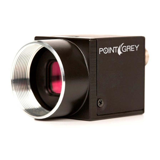
Point Grey Flea3 USB 3.0 Technical Reference 1 Welcome to Flea3 USB 3.0 Flea3 USB 3.0 Mechanical Properties 1.3.1 Physical Description 5. Status LED 1. Lens holder This light indicates the current state of the Attach lens or other optical equipment. See Lens camera operation. -
Page 27: Camera Dimensions
Point Grey Flea3 USB 3.0 Technical Reference 1 Welcome to Flea3 USB 3.0 1.3.2 Camera Dimensions To obtain 3D models, contact support@ptgrey.com. Figure 1.11: Camera Dimensional Diagram Revised 9/27/2012 Copyright ©2011-2012 Point Grey Research Inc. -
Page 28: Tripod Adapter Dimensions
Point Grey Flea3 USB 3.0 Technical Reference 1 Welcome to Flea3 USB 3.0 1.3.3 Tripod Adapter Dimensions Figure 1.12: Tripod Adapter Dimensional Diagram 1.3.4 Lens Mounting Lenses are not included with individual cameras. Related Knowledge Base Articles Title Article Selecting a lens for your camera Knowledge Base Article 345 The FL3-U3-13S2 and FL3-U3-32S2 lens mount is compatible with CS-mount lenses. -
Page 29: Back Flange Distance
Point Grey Flea3 USB 3.0 Technical Reference 1 Welcome to Flea3 USB 3.0 1.3.4.1 Back Flange Distance The Back Flange Distance (BFD) is offset due to the presence of both a 1 mm infrared cutoff (IRC) filter and a 0.5 mm sensor package window. -
Page 30: Infrared Cut-Off Filters
Infrared Cut-Off Filters Point Grey color camera models are equipped with an additional infrared (IR) cut-off filter. This filter can reduce sensitivity in the near infrared spectrum and help prevent smearing. The properties of this filter are illustrated in the results below. -
Page 31: Handling Precautions And Camera Care
Do not open the camera housing. Doing so voids the Hardware Warranty described at the beginning of this manual. Your Point Grey digital camera is a precisely manufactured device and should be handled with care. Here are some tips on how to care for the device. - Page 32 Point Grey Flea3 USB 3.0 Technical Reference 1 Welcome to Flea3 USB 3.0 To reduce heat, use a cooling fan to set up a positive air flow around the camera, taking into consideration the following precautions: Mount the camera on a heat sink, such as a camera mounting bracket, made out of a heat-conductive material like aluminum.
-
Page 33: Camera Interface And Connectors
Point Grey Flea3 USB 3.0 Technical Reference 1 Welcome to Flea3 USB 3.0 Camera Interface and Connectors 1.5.1 USB 3.0 Connector The camera is equipped with a USB 3.0 Micro-B connector that is used for data transmission, camera control and power. For more detailed information, consult the USB 3.0 specification available from http://www.usb.org/developers/docs/. -
Page 34: Interface Cables
+3.3 V Power external circuitry up to 150 mA Point Grey sells a 12 V wall-mount power supply equipped with a HR25 8-pin GPIO wiring harness for connecting to the camera (Part No. ACC-01-9006). For more information, see the miscellaneous product accessories page on the Point Grey website. -
Page 35: Getting Started With Flea3 Usb
(on page 41) CS-mount (or C-mount with adaptor)/C-mount (FL3-U3-13Y3) Lens (on page 15) Interface card (on page 20) Point Grey sells a number of the additional parts required for installation. To purchase, visit the Point Grey Webstore or the Products Accessories page. -
Page 36: Installing Your Interface Card And Software
Point Grey Flea3 USB 3.0 Technical Reference 2 Getting Started with Flea3 USB 3.0 Installing Your Interface Card and Software 1. Install your Interface Card Ensure the card is installed per the manufacturer's instructions. Alternatively, use your PC's built-in host controller, if equipped. -
Page 37: Installing Your Camera
Check Device Manager to confirm that installation was successful. a. Go to the Start menu, select Run, and enter devmgmt.msc. Verify the camera is listed under "Point Grey Research Devices." b. Run the FlyCap2 program: Start-> Point Grey Research->FlyCapture2-> FlyCap2 The FlyCap2 program can be used to test the camera's image acquisition capabilities. -
Page 38: Controlling The Camera
The FlyCap2 application is a generic, easy-to-use streaming image viewer included with the FlyCapture2 SDK that can be used to test many of the capabilities of your compatible Point Grey camera. It allows you to view a live video stream from the camera, save individual images, adjust the various video formats, frame rates, properties and settings of the camera, and access camera registers directly. -
Page 39: Values
Using the Absolute Value Registers Many Point Grey cameras implement “absolute” modes for various camera settings that report real-world values, such as shutter time in seconds (s) and gain value in decibels (dB). Using these absolute values is easier and more efficient than applying complex conversion formulas to the information in the Value field of the associated Control and Status Register. -
Page 40: Configuring Camera Setup
2.5.1 Configuring Camera Drivers Point Grey has created its own Extensible Host Controller Interface (xHCI) driver that is compatible with several USB 3.0 host controller chipsets. The PGRxHCI driver offers the best compatibility between the camera and host controller; Point Grey recommends using this driver when using Point Grey USB 3.0 cameras. - Page 41 Point Grey Flea3 USB 3.0 Technical Reference 2 Getting Started with Flea3 USB 3.0 Related Knowledge Base Articles Title Article Knowledge Base Article 389 Setting up multiple USB 3.0 cameras Revised 9/27/2012 Copyright ©2011-2012 Point Grey Research Inc.
-
Page 42: General Camera Operation
41. The camera selects whichever power source is supplying a higher voltage. Point Grey sells a 12 V wall-mount power supply equipped with a HR25 8-pin GPIO wiring harness for connecting to the camera (Part No. ACC-01-9006). For more information, see the... -
Page 43: Serial_Number: 1F20H
Point Grey Flea3 USB 3.0 Technical Reference 3 General Camera Operation Main Board Information—This specifies the type of camera (according to the main printed circuit board). Sensor Board Information—This specifies the type of imaging sensor used by the camera. Voltage—This allows the user to access and monitor the input as well as several of the internal voltages of the cameras. -
Page 44: Sensor_Board_Info: 1F28H
Point Grey Flea3 USB 3.0 Technical Reference 3 General Camera Operation 3.2.3 SENSOR_BOARD_INFO: 1F28h The interpretation of this register varies depending on the camera type, as defined in the MAIN_ BOARD_ INFO register 0x1F24 (page 30) . Read MAIN_ BOARD_INFO to determine how to use the Sensor_Type_x fields. -
Page 45: Temperature: 82Ch
Point Grey Flea3 USB 3.0 Technical Reference 3 General Camera Operation 3.2.6 TEMPERATURE: 82Ch Format: Field Description Presence of this feature Presence_Inq 0: Not Available, 1: Available [1-19] Reserved Value. Value [20-31] In Kelvin (0°C = 273.15K) in increments of one-tenth (0.1) of a Kelvin 3.2.7... -
Page 46: Memory_Save: 618H
Point Grey Flea3 USB 3.0 Technical Reference 3 General Camera Operation Shutter (including Absolute Value, Auto Shutter Range, and Sharpness (page 101) Shutter Delay) (page 111) Gain (including Absolute Value and Auto Gain Range) (page White Balance (page 109) (page 100) GPIO Pin Modes... - Page 47 Point Grey Flea3 USB 3.0 Technical Reference 3 General Camera Operation Register Name Offset CURRENT_FRAME_RATE 600h CURRENT_VIDEO_MODE 604h CURRENT_VIDEO_FORMAT 608h CAMERA_POWER 610h CUR_SAVE_CH 620h BRIGHTNESS 800h AUTO_EXPOSURE 804h SHARPNESS 808h WHITE_BALANCE 80Ch 810h SATURATION 814h GAMMA 818h SHUTTER 81Ch GAIN...
-
Page 48: On-Camera Frame Buffer
Point Grey Flea3 USB 3.0 Technical Reference 3 General Camera Operation Register Name Offset GPIO_STRPAT_MASK_PIN_x 1118h, 1128h, 1138h, 1148h FRAME_INFO 12F8h IMAGE_POSITION 008h IMAGE_SIZE 00Ch COLOR_CODING_ID 010h UDP_PORT 1F1Ch DESTINATION_IP 1F34h On-Camera Frame Buffer The camera has 32 MB of memory that can be used for temporary image storage. This may be useful in cases such as: Retransmission of an image is required due to data loss or corruption. -
Page 49: Image_Retransmit: 634H
Point Grey Flea3 USB 3.0 Technical Reference 3 General Camera Operation Although it is possible to repeatedly transmit the same image, there is no way to access images that are older than the last image transmitted. Whether by enabling trigger or disabling isochronous data, switching out of a free running mode leaves the last image transmitted in an undefined state. -
Page 50: Example: Storing Images For Later Transmission Using Registers
Point Grey Flea3 USB 3.0 Technical Reference 3 General Camera Operation 1. Read the current state of the IMAGE_RETRANSMIT register 634h: Read 634h 00 07 00 00 Reading register 634h indicates that the frame buffer mechanism is currently disabled, and in the current imaging mode, the system is capable of storing up to 7 images. -
Page 51: Non-Volatile Flash Memory
Point Grey Flea3 USB 3.0 Technical Reference 3 General Camera Operation 4. Transmit two images: Write 61Ch 80 00 00 00 Write 61Ch 80 00 00 00 Read 634h C0 07 00 02 Writing 1 to bit 0 of register 61Ch results in a single image being transmitted and the number of images available being decremented by one. ... -
Page 52: Camera Firmware
Firmware is programming that is inserted into the programmable read-only memory (programmable ROM) of most Point Grey cameras. Firmware is created and tested like software. When ready, it can be distributed like other software and installed in the programmable read-only memory by the user. -
Page 53: Firmware_Build_Date: 1F64H
Point Grey Flea3 USB 3.0 Technical Reference 3 General Camera Operation Format: Field Description Major [0-7] Major revision number Minor [8-15] Minor revision number Type of release: 0: Alpha Type [16-19] 1: Beta 2: Release Candidate 3: Release Revision [20-31] Revision number 3.6.4... -
Page 54: Input/Output Control
Power can be provided through the GPIO interface. The camera selects whichever power source is supplying a higher voltage. Point Grey sells a 12 V wall-mount power supply equipped with a HR25 8-pin GPIO wiring harness for connecting to the camera (Part No. ACC-01-9006). For more information, see the... -
Page 55: Gpio Mode 2: Asynchronous (External) Trigger
Point Grey Flea3 USB 3.0 Technical Reference 4 Input/Output Control 4.2.3 GPIO Mode 2: Asynchronous (External) Trigger When a GPIO pin is put into GPIO Mode 2, and an external trigger mode is enabled (which disables isochronous data transmission), the camera can be asynchronously triggered to grab an image by sending a voltage transition to the pin. -
Page 56: Synchronizing Image Capture With An Output Trigger Or Strobe
Point Grey Flea3 USB 3.0 Technical Reference 4 Input/Output Control 4.3.1 Synchronizing Image Capture with an Output Trigger or Strobe The following diagrams illustrate the timing of an output trigger, such as a strobe, with both a global and a rolling shutter in free-running mode. -
Page 57: Example: Setting A Gpio Pin To Strobe (Using The Camera Registers)
Point Grey Flea3 USB 3.0 Technical Reference 4 Input/Output Control As an example, if the output trigger is a strobe light, the light from the second frame will appear in the first frame as well. To reduce this effect, slow the frame rate to increase the time between frames. If the slower frame rate is not feasible, or the reduction of the effect not complete, a camera with a global shutter is recommended. - Page 58 Point Grey Flea3 USB 3.0 Technical Reference 4 Input/Output Control Determine Strobe Support The next step is to determine whether our desired strobe pin, GPIO2, is capable of outputting a strobe signal. To do this, get the value of the appropriate STROBE_ x_ INQ register (page 47);...
-
Page 59: Example: Setting A Gpio Pin To Strobe (Using The Flycapture Api)
Point Grey Flea3 USB 3.0 Technical Reference 4 Input/Output Control Duration_Value/Delay_Value Real Time (ms) 0x600 0x800 0x900 0xA00 0xB00 0xC00 0xD00 0xE00 0xF00 0xFFF 63.93 For example, to achieve a 500us delay and 1ms duration we calculate: Delay_Value = 0.0005s * 1024000Hz = 512 = 0x200 Duration_Value = 0.001s * 1024000Hz = 1024 = 0x400... -
Page 60: Strobe Signal Output Registers
Point Grey Flea3 USB 3.0 Technical Reference 4 Input/Output Control 4.3.4 Strobe Signal Output Registers This section describes the control and inquiry registers for the Strobe Signal functionality. 4.3.4.1 Strobe Output Registers To calculate the base address for an offset CSR: 1. -
Page 61: Gpio_Strpat_Ctrl: 110Ch
Point Grey Flea3 USB 3.0 Technical Reference 4 Input/Output Control Offset Name Field Description Presence of this feature Presence_Inq 0: Not Available, 1: Available [1-5] Reserved Read: read a status Write: ON or OFF this function 0: OFF, 1: ON If this bit = 0, other fields will be read only. -
Page 62: Gpio_Strpat_Mask_Pin: 1118H-1148H
Point Grey Flea3 USB 3.0 Technical Reference 4 Input/Output Control Field Description Read-only The value of the bit index defined in GPIO_x_STRPAT_MASK that will be used Current_Count [28-31] during the next image’s strobe. Current_Count increments at the same time as the strobe start signal occurs. -
Page 63: Pulse Width Modulation (Pwm)
Point Grey Flea3 USB 3.0 Technical Reference 4 Input/Output Control Pulse Width Modulation (PWM) When a GPIO pin is set to PWM (GPIO Mode 4), the pin will output a specified number of pulses with programmable high and low duration. -
Page 64: Gpio_Xtra_Pin: 1114H-1144H
Point Grey Flea3 USB 3.0 Technical Reference 4 Input/Output Control Field Description For Modes 0, 1, and 2: Data field 0 = 0 V (falling edge), 1 = +3.3 V (rising edge) Data [31] For Mode 4 (PWM): see below Number of PWM pulses Read: The current count;... -
Page 65: Serial Output Transaction (Transmitting Data)
Point Grey Flea3 USB 3.0 Technical Reference 4 Input/Output Control Related Knowledge Base Articles Title Article Knowledge Base Article 151 Configuring and testing the RS-232 serial port SIO Buffers Both the transmit and receive buffers are implemented as circular buffers that may exceed the 255 byte maximum. -
Page 66: Serial Input Transaction (Receiving Data)
Point Grey Flea3 USB 3.0 Technical Reference 4 Input/Output Control Step Action Register Input/Expected Output 4. Open a HyperTerminal window and create a new connection, setting the COM Port Settings to match the current camera settings obtained in step 3. -
Page 67: Example: Receiving Characters From A Pc
Point Grey Flea3 USB 3.0 Technical Reference 4 Input/Output Control 4.5.2.1 Example: Receiving Characters from a PC This example describes how to send four (4) characters from the PC to the camera’s serial port. Microsoft’s HyperTerminal program (Start Menu > All Programs > Accessories > Communications) is used to send the characters received from the camera. The process detailed by the table below involves the user enabling receive, having... -
Page 68: Transmitting And Receiving Data Simultaneously
Point Grey Flea3 USB 3.0 Technical Reference 4 Input/Output Control Repeat steps above, and receive characters in sets of four using register 70100h; or Do a block read of all of the characters using registers 0x70104 – 0x701FF. For example, if 12 characters were received (0x70008 = 0x0C000000), Set Register 0x70008 to 0x000C0000 and begin reading the bytes starting at 0x70104 (see the FlyCapture API documentation for information on doing block transfers). - Page 69 Point Grey Flea3 USB 3.0 Technical Reference 4 Input/Output Control Offset Name Field Description SIO_ SIO_CONTROL_ Control_ 32-bit offset of the SIO CSRs from the base address of initial register 488h [0-31] CSR_INQ Quadlet_ space Offset Baud rate setting Read: Get current baud rate...
- Page 70 Point Grey Flea3 USB 3.0 Technical Reference 4 Input/Output Control Offset Name Field Description Receive enable Indicates if the camera's ability to receive data has been enabled. Enabling this register causes the receive capability to be immediately Base + SERIAL_ started.
- Page 71 Point Grey Flea3 USB 3.0 Technical Reference 4 Input/Output Control Offset Name Field Description SIO receive buffer status RECEIVE_ Indicates the number of bytes that have arrived at the camera but have Base + BUFFER_ RBUF_ST [0-8] yet to be queued to be read.
-
Page 72: Gpio Electrical Characteristics
Point Grey Flea3 USB 3.0 Technical Reference 4 Input/Output Control Offset Name Field Description Character_2 Read: Read character from receive buffer+2. Padding data if data is not Char_2 [17-23] available. Write: Write character to transmit buffer+2. Padding data if data is invalid. -
Page 73: Gpio1 (Opto-Isolated Output) Circuit
Point Grey Flea3 USB 3.0 Technical Reference 4 Input/Output Control Figure 4.1: Optical input circuit Logical 0 input voltage: 0 VDC to +1 VDC (voltage at OPTO_IN) Logical 1 input voltage: +1.5 VDC to +24 VDC (voltage at OPTO_IN) Maximum input current: 8.3 mA Behavior between 1 VDC and 1.5 VDC is undefined and input voltages between those values should be avoided... -
Page 74: Gpio 2/3 (Bi-Directional) Circuit
Point Grey Flea3 USB 3.0 Technical Reference 4 Input/Output Control The following table lists several external voltage and resistor combinations that have been tested to work with the opto-isolated output. External Voltage External Resistor OPTO_OUT Voltage OPTO_OUT Current 3.3 V 1 kΩ... - Page 75 Point Grey Flea3 USB 3.0 Technical Reference 4 Input/Output Control External Resistor External Voltage GPIO2/3 Voltage external 3.3 V 1 kΩ 0.157 V 1 kΩ 0.218 V 12 V 1 kΩ 0.46 V 24 V 1 kΩ 0.86 V The following table lists the switching times for a standard GPIO pin, assuming an output VCC of 5V and a 1 kΩ resistor.
-
Page 76: Video Formats, Modes And Frame Rates
“binning.” Some modes implement a combination of ROI and binning. On Point Grey cameras, binning refers to the aggregation of pixels. Analog binning is aggregation that occurs before the analog to digital conversion. Digital binning is aggregation that occurs after the analog to digital conversion. Unless specified otherwise, color data is maintained in binning modes. -
Page 77: Video Mode Descriptions
Point Grey Flea3 USB 3.0 Technical Reference 5 Video Formats, Modes and Frame Rates Additional binning information can be obtained by reading the FORMAT_7_ RESIZE_INQ (page 144) register 0x1AC8. The implementation of Format 7 modes and the frame rates that are possible are not specified by the IIDC, and are subject to change across firmware versions. - Page 78 Point Grey Flea3 USB 3.0 Technical Reference 5 Video Formats, Modes and Frame Rates Mode 0 Mode 0 allows only for specifying a region of interest, and does not perform any binning. Frame rate does not increase when ROI size is reduced.
-
Page 79: Calculating Format 7 Frame Rates
Point Grey Flea3 USB 3.0 Technical Reference 5 Video Formats, Modes and Frame Rates On FL3-U3-32S2 models, the ROI size can range from 16 to 2080 pixels wide and 2 to 1080 pixels high, making the minimum image size 16 x 2 and the maximum size 2080 x 1080. The ROI can change position within the entire 2080 x 1552 pixel array. -
Page 80: Raw
Point Grey Flea3 USB 3.0 Technical Reference 5 Video Formats, Modes and Frame Rates Pixel Format Bits per Pixel Mono 8, Raw 8 Mono 12, Raw 12, YUV 411 Mono 16, Raw 16, YUV 422 RGB 8, YUV 444 5.2.1 Raw is a pixel format where image data is Bayer RAW untouched by any on board processing. -
Page 81: Y16 (16-Bit Mono) Image Acquisition
Point Grey Flea3 USB 3.0 Technical Reference 5 Video Formats, Modes and Frame Rates Related Knowledge Base Articles Title Article Knowledge Base Article 313 Understanding YUV data formats 5.2.5 Y16 (16-bit Mono) Image Acquisition The camera can output Y16 (16 bits-per-pixel) mono images. Because the camera's A/D converter is less than 16 bits, unused bits are zero. -
Page 82: Supported Formats, Modes And Frame Rates
Point Grey Flea3 USB 3.0 Technical Reference 5 Video Formats, Modes and Frame Rates Format: Field Description Presence of this feature. Presence_Inq 0: Not Available, 1: Available [1-30] Reserved. [31] Value Bayer_Mono_Ctrl 0: Disable raw Bayer output in mono modes, 1: Enable raw Bayer output in mono modes... -
Page 83: Table 5.2: Fl3-U3-13S2C Custom Formats, Modes And Frame Rates
Point Grey Flea3 USB 3.0 Technical Reference 5 Video Formats, Modes and Frame Rates Mode 1 Pixel Format 656 x 524 640 x 480 320 x 240 160 x 120 All Formats Mode 7 Pixel Format 1328 x 1048 1280 x 960... -
Page 84: Fl3-U3-13Y3 Video Modes
Point Grey Flea3 USB 3.0 Technical Reference 5 Video Formats, Modes and Frame Rates 5.3.2 FL3-U3-13Y3 Video Modes 5.3.2.1 FL3-U3-13Y3 Standard Formats, Modes and Frame Rates Modes 15 FPS 30 FPS 60 FPS • • • 1280 x 960 Y8 •... -
Page 85: Fl3-U3-13E4 Video Modes
Point Grey Flea3 USB 3.0 Technical Reference 5 Video Formats, Modes and Frame Rates 5.3.3 FL3-U3-13E4 Video Modes 5.3.3.1 FL3-U3-13E4 Standard Formats, Modes and Frame Rates Models: • 13E4M • 13E4C Modes 1.875 FPS 3.75 FPS 7.5 FPS 15 FPS 30 FPS 60 FPS •... -
Page 86: Fl3-U3-32S2 Video Modes
Point Grey Flea3 USB 3.0 Technical Reference 5 Video Formats, Modes and Frame Rates Table 5.5: FL3-U3-13E4C Custom Formats, Modes and Frame Rates Mode 0 Pixel Format 1280 x 1024 1280 x 960 640 x 480 320 x 240 160 x 120... -
Page 87: Fl3-U3-32S2 Custom Formats, Modes And Frame Rates
Point Grey Flea3 USB 3.0 Technical Reference 5 Video Formats, Modes and Frame Rates 5.3.4.2 FL3-U3-32S2 Custom Formats, Modes and Frame Rates Many USB 3.0 PCI Express Gen 2.0 motherboards limit data rates to ~180 MByte/s. The FlyCap2 Camera Selection dialog shows the supported PCIe bus speed. If you select a video format/mode that requires data rates above what is supported, the camera will skip images. -
Page 88: Fl3-U3-88S2 Video Modes
Point Grey Flea3 USB 3.0 Technical Reference 5 Video Formats, Modes and Frame Rates Mode 7 Pixel Format 2080 x 1552 1600 x 1200 1280 x 960 640 x 480 320 x 240 160 x 120 All Formats Mode 8... -
Page 89: Video Format, Mode, And Frame Rate Settings
Point Grey Flea3 USB 3.0 Technical Reference 5 Video Formats, Modes and Frame Rates Mode 0 Pixel Format 4096 x 2160 1600 x 1200 1280 x 960 640 x 480 320 x 240 160 x 120 16-bit (Mono, Raw, YUV422) 24-bit (RGB, YUV444) *In Mode 0 24-bit, the FL3-U3-88S2C supports a maximum size of 7.5 MP (for example, 3440 x 2160 or 4096 x 1820) -
Page 90: Current_Frame_Rate: 600H
Point Grey Flea3 USB 3.0 Technical Reference 5 Video Formats, Modes and Frame Rates Format: Field Description Presence of this feature Presence_Inq 0: Not Available, 1: Available Absolute value control Abs_Control 0: Control in the Value field, 1: Control in the Absolute value CSR. -
Page 91: Current_Video_Mode: 604H
Point Grey Flea3 USB 3.0 Technical Reference 5 Video Formats, Modes and Frame Rates 5.4.3 CURRENT_VIDEO_MODE: 604h Format: Field Description Current video mode Cur_V_Mode [0-3] Mode_0 .. Mode_8 [4-31] Reserved. 5.4.4 CURRENT_VIDEO_FORMAT: 608h Format: Field Description Current video format Cur_V_Format [0-2] Format_0 .. -
Page 92: Image Acquisition
Point Grey Flea3 USB 3.0 Technical Reference 6 Image Acquisition Image Acquisition Global Shutter For cameras with a global shutter sensor, for each frame all of the lines start and stop exposure at the same time. The exposure time for each line is the same. Following exposure, data readout begins. The readout time for each line is the same but the start and end times are staggered. -
Page 93: Rolling Shutter With Global Reset
Point Grey Flea3 USB 3.0 Technical Reference 6 Image Acquisition One advantage of a rolling shutter is increased sensitivity. However, because exposure starts at different times throughout the frame, there are known artifacts such as skew, wobble, and partial exposure. For more information, Rolling Shutter Artifacts on page 128. -
Page 94: Asynchronous Triggering
Point Grey Flea3 USB 3.0 Technical Reference 6 Image Acquisition An advantage of a rolling shutter with global reset is a reduction in image artifacts typical of rolling shutters such as skew and wobble. However, because exposure lengthens throughout the frame, there may be a gradual increase in brightness from top to bottom of an image. -
Page 95: Minimum Trigger Pulse Length
Point Grey Flea3 USB 3.0 Technical Reference 6 Image Acquisition Figure 6.1: External trigger timing characteristics It is possible for users to measure this themselves by configuring one of the camera’s GPIO pins to output a strobe pulse (see Programmable Strobe Output on page 42) and connecting an oscilliscope up to the input trigger pin and the output strobe pin. -
Page 96: Camera Behavior Between Triggers
Point Grey Flea3 USB 3.0 Technical Reference 6 Image Acquisition 6.4.4 Camera Behavior Between Triggers When operating in external trigger mode, the camera clears charges from the sensor at the horizontal pixel clock rate determined by the current frame rate. For example, if the camera is set to 10 FPS, charges are cleared off the sensor at a horizontal pixel clock rate of 15 KHz. -
Page 97: Trigger Modes
Point Grey Flea3 USB 3.0 Technical Reference 6 Image Acquisition 6.4.6 Trigger Modes 6.4.6.1 Trigger Mode 0 (“Standard External Trigger Mode”) Trigger Mode 0 is best described as the standard external trigger mode. When the camera is put into Trigger Mode 0, the camera starts integration of the incoming light from external trigger input falling/rising edge. -
Page 98: Trigger Mode 15 ("Multi-Shot Trigger Mode")
Point Grey Flea3 USB 3.0 Technical Reference 6 Image Acquisition Figure 6.4: Trigger Mode 1 (“Bulb Shutter Mode”) For FL3-U3-32S2 and FL3-U3-88S2 models operating in this trigger mode, exposure is controlled by the global reset feature of the sensor. This feature may reduce distortion artifacts typical of rolling shutter sensors. -
Page 99: Example: Asynchronous Hardware Triggering (Using The Camera Registers)
Point Grey Flea3 USB 3.0 Technical Reference 6 Image Acquisition Figure 6.5: Trigger Mode 15 (“Multi-Shot Trigger Mode”) FL3-U3-32S2 and FL3-U3-88S2 models operating in this trigger mode, if the number of acquired images is 1, exposure is controlled by the global reset feature of the sensor. This feature may reduce distortion artifacts typical of rolling shutter sensors. - Page 100 Point Grey Flea3 USB 3.0 Technical Reference 6 Image Acquisition Configure a Different GPIO Pin to be an External Trigger If you wish to use a different GPIO pin as the external trigger instead of the default trigger, you will need to configure the specific pin to be an input trigger, then configure the camera to use this newly allocated trigger pin.
-
Page 101: Example: Asynchronous Hardware Triggering (Using The Flycapture Api)
Point Grey Flea3 USB 3.0 Technical Reference 6 Image Acquisition Ensuring Trigger is Armed It is possible for the camera to be in asynchronous trigger mode but not be ready to accept a trigger. The reason is the camera may be currently exposing an image; the camera is only ready to be triggered again when this image finishes integrating. -
Page 102: Asynchronous Trigger Settings
Point Grey Flea3 USB 3.0 Technical Reference 6 Image Acquisition Figure 6.6: Software trigger timing The time from when the software trigger is written on the camera to when the start of integration occurs can only be approximated. The average time from register write request to register write response is approximately 49.85 us. The "write success"... -
Page 103: 6.4.10.1 Trigger_Mode: 830H
Point Grey Flea3 USB 3.0 Technical Reference 6 Image Acquisition 6.4.10.1 TRIGGER_MODE: 830h Control of the register is via the ON_OFF bit and the Trigger_Mode and Parameter fields. Format Field Description Presence of this feature Presence_Inq 0: Not Available, 1: Available... -
Page 104: 6.4.10.3 Pio_Direction: 11F8H
Point Grey Flea3 USB 3.0 Technical Reference 6 Image Acquisition Field Description Read: read a status Write: ON or OFF for this feature ON_OFF 0: OFF, 1: ON If this bit = 0, other fields will be read only [7-19]... -
Page 105: 6.4.10.6 Iso_En/Continuous_Shot: 614H
Point Grey Flea3 USB 3.0 Technical Reference 6 Image Acquisition Format: Field Description Isochronous channel number for video data transmission ISO_Channel [0-3] (Except for Format_6) [4-5] Reserved Isochronous transmit speed code. (Except for Format_6) 0 = 100 Mbps ISO_Speed [6-7]... - Page 106 Point Grey Flea3 USB 3.0 Technical Reference 6 Image Acquisition Format: Field Description 1 = only one frame of video data is transmitted. (Self cleared after transmission) One_Shot Ignored if ISO_EN = 1 1 = N frames of video data is transmitted. (Self cleared after transmission)
-
Page 107: Imaging Parameters And Control
Point Grey Flea3 USB 3.0 Technical Reference 7 Imaging Parameters and Control Imaging Parameters and Control Overview of Imaging Parameters The camera supports control over the following imaging parameters: Imaging More Register Control FlyCapture API Examples Parameter Information Example: Setting Brightness Using... -
Page 108: Brightness
Point Grey Flea3 USB 3.0 Technical Reference 7 Imaging Parameters and Control Users can define the values for manual operation of a feature. Brightness Brightness, also known as offset or black level, controls the level of black in an image. -
Page 109: Example: Setting Brightness Using The Flycapture Api
Point Grey Flea3 USB 3.0 Technical Reference 7 Imaging Parameters and Control Field Description Read: read a current mode Write: set the mode A_M_Mode 0: Manual, 1: Automatic [8-19] Reserved Value. Value [20-31] A write to this value in ‘Auto’ mode will be ignored. -
Page 110: Gain: 820H
Point Grey Flea3 USB 3.0 Technical Reference 7 Imaging Parameters and Control 7.3.1 GAIN: 820h The value field in this register can be set in three ways: Method Description The user sets the value is set via the absolute register. The Value field becomes read only and reflects Absolute the converted absolute value. -
Page 111: Example: Setting Gain Using The Flycapture Api
Point Grey Flea3 USB 3.0 Technical Reference 7 Imaging Parameters and Control 7.3.2 Example: Setting Gain Using the FlyCapture API The following FlyCapture 2.0 code snippet adjusts gain to 10.5 dB using the C++ interface, and assumes a Camera object cam. -
Page 112: Example: Setting Saturation Using The Flycapture Api
Point Grey Flea3 USB 3.0 Technical Reference 7 Imaging Parameters and Control Formulas for converting the fixed point (relative) values to floating point (absolute) values are not provided. Users wishing to work with real-world values should refer to Absolute Value CSRs (page 148). -
Page 113: Hue
Point Grey Flea3 USB 3.0 Technical Reference 7 Imaging Parameters and Control //Ensure the property is set up to use absolute value control. prop.absControl = true; //Set the absolute value of saturation to 200%. prop.absValue = 200; //Set the property. -
Page 114: Example: Setting Hue Using The Flycapture Api
Point Grey Flea3 USB 3.0 Technical Reference 7 Imaging Parameters and Control Field Description One push auto mode (controlled automatically only once) Read: 0: Not in operation, 1: In operation One_Push Write: 1: Begin to work (self-cleared after operation) If A_M_Mode = 1, this bit is ignored... -
Page 115: Sharpness: 808H
Point Grey Flea3 USB 3.0 Technical Reference 7 Imaging Parameters and Control than 1000 it is blurred. When sharpness is in auto mode and gain is low, then a small amount of sharpening is applied, which increases as gain decreases. If gain is high, a small amount of blur is applied, increasing as gain increases. -
Page 116: Example: Setting Sharpness Using The Flycapture Api
Point Grey Flea3 USB 3.0 Technical Reference 7 Imaging Parameters and Control Field Description Value. Value [20-31] A write to this value in ‘Auto’ mode will be ignored. 7.6.2 Example: Setting Sharpness Using the FlyCapture API The following FlyCapture 2.0 code snippet adjusts sharpness to 1500 using the C++ interface. The snippet assumes a Camera object cam. - Page 117 Point Grey Flea3 USB 3.0 Technical Reference 7 Imaging Parameters and Control Camera reinitialization Changing the current video mode or current video format Changing gamma The LUT can define up to 16 banks where each bank can contain up to 16 channels. Each channel shall define a table...
-
Page 118: Gamma: 818H
Point Grey Flea3 USB 3.0 Technical Reference 7 Imaging Parameters and Control 7.7.1 GAMMA: 818h The value field in this register can be set in three ways: Method Description The user sets the value is set via the absolute register. The Value field becomes read only and reflects Absolute the converted absolute value. -
Page 119: Example: Setting Gamma Using The Flycapture Api
Point Grey Flea3 USB 3.0 Technical Reference 7 Imaging Parameters and Control 7.7.2 Example: Setting Gamma Using the FlyCapture API The following FlyCapture 2.0 code snippet adjusts gamma to 1.5 using the C++ interface. The snippet assumes a Camera object cam. - Page 120 Point Grey Flea3 USB 3.0 Technical Reference 7 Imaging Parameters and Control Offset Name Field Description Read_Bank_0_Inq Capability of reading data from Bank 0 Read_Bank_1_Inq Capability of reading data from Bank 1 Read_Bank_2_Inq Capability of reading data from Bank 2...
- Page 121 Point Grey Flea3 USB 3.0 Technical Reference 7 Imaging Parameters and Control Offset Name Field Description Presence of this Feature Presence_Inq 0: Not Available, 1: Available [1-4] Reserved Read: read a status Write: ON or OFF this feature 80008h LUT_Ctrl...
-
Page 122: White Balance
Point Grey Flea3 USB 3.0 Technical Reference 7 Imaging Parameters and Control White Balance The camera supports white balance adjustment, which is a system of color correction to account for differing lighting conditions. Adjusting white balance by modifying the relative gain of R, G and B in an image enables white areas to look "whiter". -
Page 123: White_Balance: 80Ch
Point Grey Flea3 USB 3.0 Technical Reference 7 Imaging Parameters and Control 7.8.1 WHITE_BALANCE: 80Ch Format: Field Description Presence of this feature Presence_Inq 0: Not Available, 1: Available Absolute value control Abs_Control 0: Control with the Value field, 1: Control with the Absolute Value CSR... -
Page 124: Shutter
Point Grey Flea3 USB 3.0 Technical Reference 7 Imaging Parameters and Control //Set the white balance red channel to 500. prop.valueA = 500; //Set the white balance blue channel to 850. prop.valueB = 850; //Set the property. error = cam.SetProperty( &prop );... -
Page 125: Extended Shutter Times
Point Grey Flea3 USB 3.0 Technical Reference 7 Imaging Parameters and Control 7.9.1 Extended Shutter Times The maximum shutter time can be extended beyond the normal shutter range by turning off the frame rate setting. Once the frame rate is turned off, you should see the maximum value of the shutter time increase. -
Page 126: Example: Setting Shutter Using The Flycapture Api
Point Grey Flea3 USB 3.0 Technical Reference 7 Imaging Parameters and Control Fixed-point Equivalent Absolute Equivalent Absolute Value Range Value Unit Value Range 2049 to 2560 80 us 41.04 ms to 81.92 ms Format: Field Description Presence of this feature... -
Page 127: 7.10 Auto Exposure
Point Grey Flea3 USB 3.0 Technical Reference 7 Imaging Parameters and Control //Ensure auto-adjust mode is off. prop.autoManualMode = false; //Ensure the property is set up to use absolute value control. prop.absControl = true; //Set the absolute value of shutter to 20 ms. -
Page 128: Ae_Roi: 1A70 - 1A74H
Point Grey Flea3 USB 3.0 Technical Reference 7 Imaging Parameters and Control Format: Field Description Presence of this feature Presence_Inq 0: Not Available, 1: Available Absolute value control Abs_Control 0: Control with the Value field, 1: Control with the Absolute value CSR. -
Page 129: Example: Setting Auto Exposure Using The Flycapture Api
Point Grey Flea3 USB 3.0 Technical Reference 7 Imaging Parameters and Control Format: Offset Name Field Description Presence of this feature Presence_Inq 0:Not Available, 1: Available [1-5] Reserved Read: read a status 1A70h AE_ROI_CTRL Write: ON or OFF for this feature... -
Page 130: 7.11 Bayer Color Processing
Point Grey Flea3 USB 3.0 Technical Reference 7 Imaging Parameters and Control 7.11 Bayer Color Processing In color models, a Bayer tile pattern color filter array captures the intensity red, green or blue in each pixel on the sensor. The image below is an example of a Bayer tile pattern. -
Page 131: Bayer_Tile_Mapping: 1040H
Point Grey Flea3 USB 3.0 Technical Reference 7 Imaging Parameters and Control Related Knowledge Base Articles Title Article Knowledge Base Article 33 Different color processing algorithms Knowledge Base Article 37 Writing color processing software and color interpolation algorithms How is color processing performed on my camera's images? Knowledge Base Article 89 7.11.2... -
Page 132: 7.12 Image Flip/Mirror
Point Grey Flea3 USB 3.0 Technical Reference 7 Imaging Parameters and Control 7.12 Image Flip/Mirror The camera supports horizontal image mirroring. The mirror image operation is performed on the camera using the on-board frame buffer (page 35). 7.12.1 MIRROR_IMAGE_CTRL: 1054h... -
Page 133: Frame_Info: 12F8H
Point Grey Flea3 USB 3.0 Technical Reference 7 Imaging Parameters and Control If you turned on all possible options the first 40 bytes of image data would contain camera information in the following format, when accessed using the FlyCapture 2 API: (assuming unsigned char* data = rawImage.GetData();... - Page 134 Point Grey Flea3 USB 3.0 Technical Reference 7 Imaging Parameters and Control Field Description Frame-Specific Information ROI_Pos_Inq GPIO_State_Inq Strobe_Pat_Inq Frame_Count_Inq WB_CSR_Inq [10] Presence of image-specific information display 0: Not Available, 1: Available Exp_CSR_Inq [11] Bright_CSR_Inq [12] Shutter_CSR_Inq [13] Gain_CSR_Inq [14]...
-
Page 135: Troubleshooting
Point Grey Flea3 USB 3.0 Technical Reference 8 Troubleshooting Troubleshooting Support Point Grey Research endeavors to provide the highest level of technical support possible to our customers. Most support resources can be accessed through the Point Grey Product Support page. -
Page 136: Camera Diagnostics
Point Grey Flea3 USB 3.0 Technical Reference 8 Troubleshooting Camera Diagnostics Use the following parameters to monitor the error status of the camera and troubleshoot problems: Initialize—This allows the user to reset the camera to its initial state and default settings. -
Page 137: Xmit_Failure: 12Fch
Point Grey Flea3 USB 3.0 Technical Reference 8 Troubleshooting 8.2.4 XMIT_FAILURE: 12FCh Format: Field Description Presence of this feature Presence_Inq 0: Not Available, 1: Available Read: Count of failed frame transmissions. Frame_Count [1-31] Write: Reset. 8.2.5 VMODE_ERROR_STATUS: 628h Format: Field Description Error status of combination of video format, mode, frame rate and ISO_SPEED setting. -
Page 138: Status Indicator Led
Point Grey Flea3 USB 3.0 Technical Reference 8 Troubleshooting Status Indicator LED LED Status Description Not receiving power Steady green Camera receiving power (~3 seconds) Flashing yellow Initializing FPGA (~1 second) Steady yellow FPGA initialized (~1 second) Steady yellow-green Sensor powered... -
Page 139: Test Pattern
Point Grey Flea3 USB 3.0 Technical Reference 8 Troubleshooting Test Pattern The camera is capable of outputting continuous static images for testing and development purposes. The test pattern image is inserted into the imaging pipeline immediately prior to the transfer to the on-board FIFO, and is therefore not subject to changes in imaging parameters. -
Page 140: Blemish Pixel Artifacts
Pixel Defect Correction Point Grey tests for blemish pixels on each camera. The mechanism to correct blemish pixels is hard-coded into the camera firmware, and can be turned off and on by the user. Pixel correction is on by default. The correction algorithm involves applying the average color or grayscale values of neighboring pixels to the blemish pixel. -
Page 141: Rolling Shutter Artifacts
Point Grey Flea3 USB 3.0 Technical Reference 8 Troubleshooting Rolling Shutter Artifacts The rolling shutter used on the CMOS sensor of the camera may produce undesirable effects under certain conditions. Skew—Skew occurs if the camera is panning horizontally while the sensor is still exposing making vertical objects appear to be leaning. -
Page 142: Fixed Pattern Noise Artifact
With FL3-U3-13Y3, an internal sensor artifact may cause fixed pattern noise (FPN) at high saturation points on an image. FPN most commonly manifests as vertical stripes or lines. To reduce this issue, Point Grey applies flat field correction to the camera. Adjusting image parameters to avoid over saturation also minimizes this effect. -
Page 143: Appendix A: Control And Status Registers
Point Grey Flea3 USB 3.0 Technical Reference Appendix A: Control and Status Registers Appendix A: Control and Status Registers General Register Information A.1.1 Register Memory Map The camera uses a 64-bit fixed addressing model. The upper 10 bits show the Bus ID, and the next six bits show the Node ID. -
Page 144: Config Rom
Point Grey Flea3 USB 3.0 Technical Reference Appendix A: Control and Status Registers Broadcast is only available for FlyCapture2 and FireWire cameras. FireWire has the ability to write to multiple cameras at the same time. A.1.2 Config ROM A.1.2.1 Root Directory... -
Page 145: Unit Directory
Point Grey Flea3 USB 3.0 Technical Reference Appendix A: Control and Status Registers A.1.2.2 Unit Directory Offset Description [0-15] 0003h 0000h [16-31] [0-7] 0004h [8-31] unit_spec_ID (=0x00A02D) [0-7] 0008h [8-31] unit_sw_version (=0x000102) [0-7] 000Ch [8-31] unit dependent directory offset A.1.2.3... -
Page 146: Calculating Base Register Addresses Using 32-Bit Offsets
Point Grey Flea3 USB 3.0 Technical Reference Appendix A: Control and Status Registers Offset Description [0-7] 0020h [8-31] vendor_unique_info_0 [0-7] 0024h [8-31] vendor_unique_info_1 [0-7] 0028h [8-31] vendor_unique_info_2 [0-7] 002Ch [8-31] vendor_unique_info_3 A.1.3 Calculating Base Register Addresses using 32-bit Offsets The addresses for many CSRs, such as those that provide control over absolute values, custom video modes, PIO, SIO and strobe output, can vary between cameras. -
Page 147: Feature Presence Inquiry Registers
Point Grey Flea3 USB 3.0 Technical Reference Appendix A: Control and Status Registers (Bit values = 0: Not Available, 1: Available) Format: Offset Name Field Description Inquiry for advanced feature. Advanced_Feature_Inq (Vendor Unique Features) Inquiry for existence of Vmode_Error_Status Vmode_Error_Status_Inq... - Page 148 Point Grey Flea3 USB 3.0 Technical Reference Appendix A: Control and Status Registers Format: Offset Name Field Description Brightness Brightness Control Auto_Exposure Auto Exposure Control Sharpness Sharpness Control White_Balance White Balance Control Hue Control Saturation Saturation Control Gamma Gamma Control...
-
Page 149: Feature Elements Inquiry Registers
Point Grey Flea3 USB 3.0 Technical Reference Appendix A: Control and Status Registers Offset Name Field Description 32-bit offset of the PIO control CSRs (see the Parallel PIO_Control_ 484h PIO_Control_CSR_Inq [0-31] Input/Output (PIO) section) from the base address of Quadlet_Offset initial register space. - Page 150 Point Grey Flea3 USB 3.0 Technical Reference Appendix A: Control and Status Registers Offset Name Field Description 52Ch TEMPERATURE_INQ Same format as the BRIGHTNESS_INQ register Presence_Inq Presence of this feature Abs_Control_Inq Absolute value control [2-3] Reserved ReadOut_Inq Ability to read the value of this feature...
-
Page 151: Video Format Inquiry Registers
Point Grey Flea3 USB 3.0 Technical Reference Appendix A: Control and Status Registers Offset Name Field Description 540h Reserved for other FEATURE_HI_INQ 57Ch 580h ZOOM_INQ Same format as the BRIGHTNESS_INQ register 584h PAN_INQ Same format as the BRIGHTNESS_INQ register 588h... - Page 152 Point Grey Flea3 USB 3.0 Technical Reference Appendix A: Control and Status Registers Format: Offset Name Field Description Mode_0 160 x 120 YUV(4:4:4) Mode (24 bits/pixel) Mode_1 320 x 240 YUV(4:2:2) Mode (16 bits/pixel) Mode_2 640 x 480 YUV(4:1:1) Mode (12 bits/pixel)
-
Page 153: Video Frame Rate Inquiry Registers
Point Grey Flea3 USB 3.0 Technical Reference Appendix A: Control and Status Registers Offset Name Field Description Mode_0 Format 7 Mode 0 Mode_1 Format 7 Mode 1 Mode_2 Format 7 Mode 2 Mode_3 Format 7 Mode 3 V_MODE_INQ_7 19Ch Mode_4... - Page 154 Point Grey Flea3 USB 3.0 Technical Reference Appendix A: Control and Status Registers Offset Name Field Description V_RATE_INQ_0_4 210h Same format as V_RATE_INQ_0_1 Register (Format 0, Mode 1) (Format 0, Mode 4) V_RATE_INQ_0_5 214h Same format as V_RATE_INQ_0_1 Register (Format 0, Mode 1)
- Page 155 Point Grey Flea3 USB 3.0 Technical Reference Appendix A: Control and Status Registers Offset Name Field Description FrameRate_0 1.875 fps FrameRate_1 3.75 fps FrameRate_2 7.5 fps FrameRate_3 15 fps V_RATE_INQ_1_4 230h FrameRate_4 30 fps (Format 1, Mode 4) FrameRate_5 60 fps...
-
Page 156: Video Mode Control And Status Registers
Point Grey Flea3 USB 3.0 Technical Reference Appendix A: Control and Status Registers Offset Name Field Description 260h Reserved 2BFh 2E0h V_CSR_INQ_7_0 Mode_0 [0-31] CSR 32-bit offset for Format 7 Mode 0 2E4h V_CSR_INQ_7_1 Mode_1 [0-31] CSR 32-bit offset for Format 7 Mode 1... -
Page 157: Format_7_Resize_Inq: 1Ac8H
Point Grey Flea3 USB 3.0 Technical Reference Appendix A: Control and Status Registers A.3.1 FORMAT_7_RESIZE_INQ: 1AC8h This register reports all internal camera processes being used to generate images in the current video mode. For example, users can read this register to determine if pixel binning and/or subsampling is being used to achieve a non- standard custom image size. -
Page 158: Image Size And Position
Point Grey Flea3 USB 3.0 Technical Reference Appendix A: Control and Status Registers Table A.1: Custom Video Mode Inquiry Register Offset Addresses Offset Name Field Description 2E0h V_CSR_INQ_7_0 Mode_0 [0-31] 32-bit offset for Mode 0 2E4h V_CSR_INQ_7_1 Mode_1 [0-31] 32-bit offset for Mode 1... -
Page 159: A.3.2.2 Color_Coding_Id And Color_Coding_Inq
Point Grey Flea3 USB 3.0 Technical Reference Appendix A: Control and Status Registers Address Name Field Description Width of requested image region (pixels) Width [0-15] Width = Hunit * n2 Base + IMAGE_SIZE 00Ch Height of requested image region (pixels) -
Page 160: Frame_Interval_Inq
Point Grey Flea3 USB 3.0 Technical Reference Appendix A: Control and Status Registers Format: Address Name Field Description PIXEL_NUMBER_ Total number of pixels in the required image Base + 034h PixelPerFrame [0-31] area TOTAL_BYTES_HI_ Higher 32-bits of total bytes of image data per... -
Page 161: Value_Setting
Reserved Absolute Value Registers Many Point Grey cameras implement “absolute” modes for various camera settings that report real-world values, such as shutter time in seconds (s) and gain value in decibels (dB). Using these absolute values is easier and more efficient than applying complex conversion formulas to the information in the Value field of the associated Control and Status Register. -
Page 162: Absolute Value Offset Addresses
Point Grey Flea3 USB 3.0 Technical Reference Appendix A: Control and Status Registers Field Description Absolute value control 0: Control with the value in the Value field Abs_Control 1: Control with the value in the Absolute value CSR. If this bit = 1, the value in the Value field is read-only. -
Page 163: Units Of Value For Absolute Value Csr Registers
Point Grey Flea3 USB 3.0 Technical Reference Appendix A: Control and Status Registers For example: Offset Name Field Description 704h ABS_CSR_HI_INQ_1 [0..31] Auto Exposure. Base + 0h Min_Value [0-31] Min auto exposure value. Base + 4h ABS_VAL_AUTO_EXPOSURE Max_Value [0-31] Max auto exposure value. - Page 164 Point Grey Flea3 USB 3.0 Technical Reference Appendix A: Control and Status Registers float fValue; } AbsValueConversion; float fMinShutter, fMaxShutter, fCurShutter;AbsValueConversion minShutter, maxShutter, curShutter; // read the 32-bit hex value into the unsigned long member cam.ReadRegister(context, 0x910, &minShutter.ulValue ); cam.ReadRegister(context, 0x914, &maxShutter.ulValue );...
-
Page 165: Contacting Point Grey Research
Point Grey Flea3 USB 3.0 Technical Reference Contacting Point Grey Research Contacting Point Grey Research For any questions, concerns or comments please contact us via the following methods: General questions about Point Grey Research Email Technical support (existing customers only) -
Page 166: Revision History
Point Grey Flea3 USB 3.0 Technical Reference Revision History Revision History Revision Date Notes September 22, 2011 Initial Document Version with support for model FL3-U3-32S2 November 25, 2011 Added support for model FL3-U3-13S2 Fixed broken links to knowledge base articles... - Page 167 Point Grey Flea3 USB 3.0 Technical Reference Index BAYER_MONO_CTRL register 1050h BAYER_TILE_MAPPING register 1040h binning black level 16-bit Mono data format blemish pixels brightness absolute value mode 26, 148 variable in images 128 absolute values BRIGHTNESS register 800h shutter conversion 112...
- Page 168 Point Grey Flea3 USB 3.0 Technical Reference configuration sets endianness conversion formulas for camera settings 26, 148 Y16 data 68 CS-mount lens environmental conditions CSR base address error flags CURRENT register 1A58h - 1A5Ch exposure time CURRENT_FRAME_RATE register 600h extended shutter...
- Page 169 Point Grey Flea3 USB 3.0 Technical Reference Format_7 GPIO_STRPAT_MASK_PIN FORMAT_7_RESIZE_INQ register 1AC8h GPIO_XTRA register 1104h formats GPIO_XTRA_PIN register changing while triggering 83 greyscale conversion customizable (Format_7) 63 heat dissipation FPN_CTRL register 1A0Ch hexadecimal format frame buffer HORIZONTAL_LINE_FREQ register 1AF4h frame rate, partial image mode...
- Page 170 Point Grey Flea3 USB 3.0 Technical Reference output mode (GPIO) LED_CTRL register 1A14h output pins lens output pulse compatibility 15 partial image modes PCI card long shutter PGM file format for Y16 images lookup table physical description pinout LUT registers 80000h - 80048h...
- Page 171 Point Grey Flea3 USB 3.0 Technical Reference config ROM 131 HORIZONTAL_LINE_FREQ 1AF4h 32 control and status (CSRs) 25 HUE 810h 100 inquiry 26, 133 IMAGE_RETRANSMIT 634h 36 memory map 130 INITIALIZE 000h 123 registers commonly accessed ISO_CHANNEL / ISO_SPEED 60Ch 91...
- Page 172 Point Grey Flea3 USB 3.0 Technical Reference XMIT_FAILURE 12FCh 124 TEST_PATTERN register 104C reset camera to default settings 123, 131-132 TIME_FROM_BUS_RESET register 12E4h retransmitting images TIME_FROM_INITIALIZE register 12E0h rolling shutter artifacts timestamp transmission failure saturation frame count 124 SATURATION register 814h...
- Page 173 Point Grey Flea3 USB 3.0 Technical Reference white pixels WHITE_BALANCE register 80Ch XMIT_FAILURE register 12FCh Y16 data format Revised 9/27/2012 Copyright ©2011-2012 Point Grey Research Inc.
Need help?
Do you have a question about the Flea3 FL3-U3 and is the answer not in the manual?
Questions and answers