Table of Contents
Advertisement
Quick Links
Will your system support the
camera?
Recommended System Configuration:
OS—XP, Vista, Windows 7
n
CPU—2.4 GHz (or equivalent)
n
RAM—512 MB
n
Video—NVIDIAGeForce6 or later; 128 MB RAM or
n
more
Ports—Camera Link PCIe card with Full CL
n
interface
For More Information
For more information about...
Your camera's settings and capabilities
Accessing customer downloads
Selecting a lens
Supported frame grabber and cable combinations
Our online
Knowledge Base
addresses many questions.
Camera Interface
Camera Link
The camera is equipped with two (2) 26-pin female 0.05 inch SDR connectors for
video data and camera control and configuration. Pin assignments conform to the
Camera Link specification. For more information, see your camera's Technical
Reference Manual.
General Purpose I/O Connector
The camera has an 8-pin GPIO connector on the back of the case; refer to the
diagram for wire color-coding.
Diagram
Color
Pin
Black
1
White
2
Red
3
Green
4
Brown
5
Blue
6
Orange
7
Yellow
8
To configure the GPIO pins, consult the General Purpose Input/Output section
of your camera's Technical Reference Manual.
Do you have a downloads account?
The
Point Grey downloads
you operate your camera effectively, including:
Software, including CCFs (required for installation)
n
Firmware updates and release notes
n
Dimensional drawings and CAD models
n
Documentation
n
To access the downloads resources you must have a
downloads account.
1. Go to the
Point Grey downloads
2. Under Register (New Users), complete the form, then
click Submit.
After you submit your registration, you will receive an email
with instructions on how to activate your account.
See...
Technical Reference Manual
Knowledge Base Article 10142
Knowledge Base Article 10269
Knowledge Base Article 10023
Function
Description
Opto-isolated input (default Trigger
I0
in)
O1
Opto-isolated output
IO2
Input/Output/serial transmit (TX)
IO3
Input/Output/serial receive (RX)
Ground for bi-directional IO, V
GND
V pins
OPTO_GND
Ground for opto-isolated IO pins
Allows the camera to be powered
V
EXT
externally
Power external circuitry up to 150 mA
+3.3 V
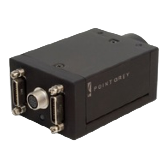
Gazelle Camera Link Digital Camera
page has many resources to help
page.
Status Indicator LED
The camera is equipped with a bi-color red/green LED. When no power is present,
the LED is off. When the camera is first connected to power, the LED first turns solid
orange (red and green on simultaneously) until the camera is initialized. Once the
camera is fully initialized, the LED turns solid green.
LED Status
Off
Orange
Steady green
Slow flashing green
Alternating red/green flashing
Solid red
Slow flashing red
Fast flashing red
Camera Care
To clean the imaging surface of your camera, follow the steps outlined in
Base Article
10243.
Extended exposure to bright sunlight, rain, dusty environments, etc. may cause
problems with the electronics and optics of the system.
Avoid excessive shaking, dropping, or mishandling of the device.
Do not open the camera housing. Doing so voids the Hardware Warranty.
, +3.3
Avoid electrostatic charging. For more details, consult
EXT
10147.
Contacting Point Grey Research
For all general questions please contact us at info@ptgrey.com.
For technical support (existing customers only) contact us at
www.ptgrey.com/support/ticket/.
Main Office:
Mailing Address:
Point Grey Research, Inc.
12051 Riverside Way
Richmond, BC, Canada V6W 1K7
Getting Started with the
Do you have all the parts you need?
To install your camera you will need the following
components:
Camera Link cable
n
8-pin GPIO cable
n
C-mount Lens
n
Tripod adapter (optional)
n
Interface card
n
Point Grey sells a number of the additional parts
required for installation. To purchase, visit the
Grey website Accessories
page.
Point Grey provides camera configuration files (CCFs)
for using the camera with compatible frame grabbers.
(Download
CCFs)
Description
Not receiving power
Initialization
Receiving power and successful camera initialization
Streaming images or performing internal operation
Firmware update in progress
Input voltage is out of tolerance
Firmware initialization problem - contact technical
General error - contact technical
support
Knowledge Base Article
Tel: +1 (604) 242-9937
Toll Free +1 (866) 765-0827
(North America only)
Fax: +1 (604) 242-9938
Email:
sales@ptgrey.com
Point
support
Knowledge
Advertisement
Table of Contents

Subscribe to Our Youtube Channel
Related Manuals for Point Grey Gazelle


Summary of Contents for Point Grey Gazelle
- Page 1 Ports—Camera Link PCIe card with Full CL Interface card To access the downloads resources you must have a interface Point Grey sells a number of the additional parts downloads account. required for installation. To purchase, visit the Point 1. Go to the Point Grey downloads page.
- Page 2 Login to the Point Grey downloads page. b. Select your Gazelle from the drop-down lists and click the Search button. c. Click on the Software search results to expand the list. d. Click on Gazelle Camera Configuration Files to begin the download.
Need help?
Do you have a question about the Gazelle and is the answer not in the manual?
Questions and answers