Table of Contents
Advertisement
Advertisement
Table of Contents
Troubleshooting

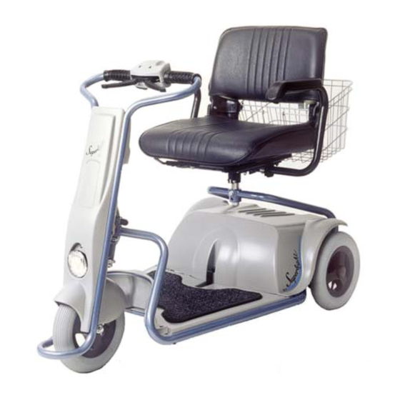
Related Manuals for Afikim Superlight SL-3


Summary of Contents for Afikim Superlight SL-3
- Page 2 Chapter : "EMI WARNING” before operating the Superlight . Serial Number Label is affixed to the Tiller: See Fig 10. CE CERTIFICATION The Afikim Electric Vehicles Ref. Registration Number with the Competent Authority (UK) CA 000292. Our Authorized Representative with the Competent Authorities is: MEDES LTD.POB 231...
-
Page 3: Table Of Contents
________________________________________________________ CONTENTS Subject Page CHAPTER 1 - DELIVERY and UNPACKING ........3 CHAPTER 2 - ASSEMBLY ..............5 CHAPTER 3 - OPERATING INSTRUCTIONS ........12 CHAPTER 4 - DISASSEMBLY ............16 CHAPTER 5 - CHARGING BATTERIES ..........19 CHAPTER 6 - STORING IN CAR............21 CHAPTER 7 - TROUBLESHOOTING ..........22 BATTERY CHARGER - TROUBLESHOOTING........23 CHAPTER 8 - SAFETY INSTRUCTIONS .........24 CHAPTER 9 - SERVICE..............26... -
Page 4: Chapter 1 - Delivery And Unpacking
________________________________________________________ CHAPTER 1 - DELIVERY and UNPACKING The SUPERLIGHT Scooter is delivered to you packed in one Cardboard Box. . Note: The box weight 60kg (132 lb.) - do NOT attempt to lift it with out assistance. Unpack as follows (See Fig. -
Page 5: Chapter 2 - Assembly
________________________________________________________ CHAPTER 2 - ASSEMBLY Installation of the Power Unit a. Position the Superlight power Unit on the floor so that the anti tip is backward direction. b. Lay the frame at the front of the power unit (See figure 2) c. - Page 6 ________________________________________________________ e. To assure that the power unit is properly connected to the frame ,you can try and lift the frame. f. Connect the electrical connector coming from the frame to the power unit Socket (See figure 4a) . WARNING After installing the frame onto the power unit and locking it, Please check carefully that it is properly positioned and secured.
- Page 7 ________________________________________________________ Connect the Electric Plug to the Socket in the Tiller (See Figure 6). figure 6 2.3 Installation of Batteries (See Fig. 7) Note: Installation of L.H Battery is identical to R.H. Battery. L.H. Battery is shown. a. Place battery in its location on the frame. b.
- Page 8 ________________________________________________________ Installation of Batteries Cover (See Fig. 9) a. Place Batteries Cover over the Batteries . Make sure to insert the rear plates under the cover into the slots in the power unit and that the front of the cover seat properly. (See Figure 9) Figure 9 c.
-
Page 9: Figure
________________________________________________________ Seat Installation (Figure 11) Seat Installation and Adjust: a. Insert the Seat Adapter into the Seat-Bushing (1) Verify that the Seat-Bushing slot is in forward direction. (2) Install bolt and washer and tighten the bolts very well, using the attached wrench. (3) Install and tighten the securing nut very well, using attached wrench. -
Page 10: Figure
________________________________________________________ Rear Basket Installation a. Install the Rear Basket by placing it on the two Upper Support bracket at the rear of the seat back lying on the Bottom Support. (See Fig. 12). Figure 12 After the assembly make sure that: a. - Page 11 ________________________________________________________ Seating into the SUPERLIGHT a. For comfort entering into the SUPERLIGHT (See Figure 13). b. Lift the Seat Turning Lever and turn the Seat 45 or 90 degree to the side of the frame. c. Sit down and turn swivel back towards the front of the vehicle while the lever is still pulled up.
-
Page 12: Chapter 3 - Operating Instructions
________________________________________________________ CHAPTER 3 - OPERATING INSTRUCTIONS PLEASE READ THOROUGHLY CHAPTER 8 - “SAFETY INSTRUCTIONS” - BEFORE DRIVING THE SUPERLIGHT. Please charge your battery before first use (ca. 6 hours) Mount the SUPERLIGHT, insert the Key into the Slot and turn it clockwise to the (marked) ON position. - Page 13 ________________________________________________________ figure 14 figure 15 Set the Speed Selector switch as desired. When “extra-power” is needed (i.e., climbing allowed slopes) use the High speed mode. Battery Capacity Indicator (See Fig. 15) The Battery Capacity Indicator is part of the Display Panel. The indicator contains 4 red leds.
- Page 14 ________________________________________________________ Lights Operating (See Fig. 16) To switch on the SUPERLIGHT light, use the Right-Blue switch. WARNING 1. Until you get used to the SUPERLIGHT and its operational features - Speed Selector switch should be set at the Low mode (“Turtle”). 2.
- Page 15 ________________________________________________________ Charging Fuse Figure 16 In case of power fail, low battery or other fail The SUPERLIGHT can be pushed manually pulling upward the EMB manual release lever at the rear of the SUPERLIGHT (See Fig. 17) and pushing the SUPERLIGHT by hand. The SUPERLIGHT will not operate and the buzzer will beep until the manual release lever is pushed downward again, back to its original position.
-
Page 16: Chapter 4 - Disassembly
________________________________________________________ CHAPTER 4 - DISASSEMBLY Removal of Seat (See Fig. 18) a. Remove the Rear Basket by lifting it up from its Support Rod. b. Remove the Seat from the Seat Adapter by lifting the Seat straight up while turning Release Lever is pulled only when the Seat is 45ºback direction to the left. - Page 17 ________________________________________________________ Removal of Batteries Batteries can be easily removed from your SUPERLIGHT as follows - a. Remove Seat and Rear Basket (see instructions in paragraph 4.2 above). b. Open Batteries Cover - (See Fig. 20). 1) Pull back Plastic Clip 2) Push the cover backward than up a little from the rear slots in the power unit cover and than forward out .
- Page 18 ________________________________________________________ Removal of Power Unit a. Remove the Batteries. (As explained in 4.3). Disconnect the electrical connector coming from the frame to the power unit Socket (See Figure 22) Figure 22 Figure 22a c. Squeeze the rear knob at the right of the anti tip and pushed it downward until locked again.
-
Page 19: Chapter 5 - Charging Batteries
________________________________________________________ CHAPTER 5 - CHARGING BATTERIES The Battery Charger supplied with your SUPERLIGHT controls the charging operation, prevents over-charging and prolongs the life of the batteries. Read chargers instructions carefully before using the charger. Note: There is no ON/OFF power switch to the charger. Charging Batteries (See Fig. - Page 20 ________________________________________________________ e. If you are planning not to use your SUPERLIGHT for an extended period of time, we recommend charging it for two days and then disconnecting the batteries. If you have not used your SUPERLIGHT for an extended period of time, charge the batteries for at least 12 hours before driving.
-
Page 21: Chapter 6 - Storing In Car
________________________________________________________ CHAPTER 6 - STORING IN CAR (See Fig. 25) The SUPERLIGHT design, its small dimensions and low weight allow for easy and simple storage and transportation in almost all types of cars. 6.1 Take off the Seat and the Rear Basket. 6.2 Separate the Tiller from the Frame. -
Page 22: Chapter 7 - Troubleshooting
________________________________________________________ CHAPTER 7 - TROUBLESHOOTING No. Trouble Probable Cause Corrective Action Green Lamp not ON - Cables not properly - Check cables and when Key is turned, connected or need reinsert all repair connections. If the problem is not resolved call your dealer or Service Center - Main fuse on... -
Page 23: Battery Charger - Troubleshooting
________________________________________________________ BATTERY CHARGER - TROUBLESHOOTING No. Trouble Probable Cause Corrective Action Charger indicator is Faulty charger Replace charger not ON while the charger is plugged into wall outlet Charger indicator Loose contact Pull plug and insert does not change between plug and again. -
Page 24: Chapter 8 - Safety Instructions
________________________________________________________ CHAPTER 8 - SAFETY INSTRUCTIONS The SUPERLIGHT can be operated indoors, as well as outdoors on flat paved surfaces. Please note and strictly adhere to the following Safety Instructions. Additional Warnings and Notices are printed in this USER’S MANUAL ;... - Page 25 ________________________________________________________ Emergency Braking in case of danger when driving forward, Squeeze Reverse Lever to stop. In case of danger when reversing - squeeze the Forward Lever. This may cause abrupt and excessive deceleration which in turn may cause injury to user and damage to the SUPERLIGHT. WARNING Persons with impaired capacity and/or untrained persons should not operate the SUPERLIGHT under any...
-
Page 26: Chapter 9 - Service
________________________________________________________ CHAPTER 9 - SERVICE Your SUPERLIGHT is designed and built to provide a long, useful and troublefree life. Occasionally it may require service depending on the conditions and environment to which it was exposed. We recommend that for service and repair you maintain contact the authorized dealer where you purchased your SUPERLIGHT. - Page 27 ________________________________________________________ Tires and air pressure inspection As standard, the SUPERLIGHT is supplied with PU (Polyurethane) tires which does not need any service. In case of using air tires: - a. Normal air pressure in the SUPERLIGHT tires is essential for retaining the vehicle’s travel ability and stabilization. b.
-
Page 28: Chapter 10 - Specifications
________________________________________________________ CHAPTER 10 - SPECIFICATIONS * DIMENSIONS: Metric (cm) U.S. (inches) Width 24.4 Length with straight handlebars 44.5 Height of seat from floor 55-60 21.5-23.6 Ground clearance WEIGHTS : Metric (kg) U.S. (lb.) Tiller 13.2 Frame - complete 50.6 Frame (without power unit) 18.7 Power Unit 14.5... - Page 29 ________________________________________________________ OPERATIONAL CHARACTERISTICS: Metric U.S. (Cont.) Maximum allowed side angle 7.4 deg. WHEELS & MARKINGS ON TIRES: Front – PU Solid or Air tube, φ250 mm x 50 mm Rear – PU Solid or Air tube , φ250mm x 50mm GENERAL: Drive Rear Transaxle...
-
Page 30: Chapter 11 - Emi Warning
________________________________________________________ CHAPTER 11 - EMI WARNING All types of electrically powered vehicles, such as powered wheelchairs and motorized scooters (in this text all types will be referred to as “powered vehicles”) may be susceptible to electromagnetic interference (EMI), which is interfering electromagnetic energy (EM) emitted from sources such as radio stations, TV stations, amateur radio (HAM) transmitters, two way radios and cellular phones. - Page 31 ________________________________________________________ NOTE: Other types of hand held devices, such as cordless phones, laptop computers, AM/FM radios, TV sets, CD players, cassette players and small appliances such as electric shavers and hair dryers, as far as we know, are not likely to cause EMI problems to your powered vehicle.
- Page 32 ________________________________________________________...
Need help?
Do you have a question about the Superlight SL-3 and is the answer not in the manual?
Questions and answers
WIRING DIAGRAM