Table of Contents
Advertisement
Advertisement
Table of Contents

Related Manuals for Leica DNA03


Summary of Contents for Leica DNA03
- Page 1 Leica DNA03/DNA10 User Manual Version 2.0 English...
- Page 2 This manual contains important manual and always refer to this information when safety directions as well as you need to contact your agency or Leica Geosys- instructions for setting up the tems authorized service workshop. product and operating it. Refer to "Safety directions"...
-
Page 3: Symbols Used
Symbols used DANGER Immediate hazards of use that lead to personal injuries or even death. WARNING Hazards of use or inappropriate applica- tion that lead to personal injuries or even death. CAUTION Hazards of use or inappropriate applica- tion that lead to minor personal injuries but appreciatble material, financial or enviromental damage. -
Page 4: Table Of Contents
Keyboard and display .......35 Area levelling..........17 Fixed keys ............36 Computer software package Key combinations........... 36 Leica Geo Office (LGO) ......18 Navigation keys..........37 PCMCIA or CF card ......... 20 Entry keys ............38 Display keys ..........39 Equipment ..........21 Navigating the menus ........ - Page 5 Find point ..........45 Start programs........72 Wildcard-search ..........48 Set job ............73 Set line ............74 Technical hints for measurements .. 49 Set tolerances ..........76 Special measuring situations ....49 Select method ..........78 Important instrument settings......50 Check list............
- Page 6 Coding ..........101 Memory information........121 Data export ..........122 Entering a code ........102 Data import ..........124 Quick Code ..........103 Data storage........126 Menu settings ........105 Start programs ..........126 All settings..........107 Measurement program......... 127 System ............107 Measurement mode and corrective Measuring ............
- Page 7 Check and adjust......145 Stand............145 Circular level ..........145 Reticle ............146 Technical data ......... 147 Corrections/ formulas ..... 150 Accessories ........151 Sensor-error messages ....152 Index ..........153...
-
Page 8: Introduction
Leica digital levels come with a wide range of soft- ware functions. Single height measurements are easy to make and also just as easy is measuring all the elements in a line levelling job. -
Page 9: Principal Of Measurement
(The sensitivity of the sensor ran- ges from the highest frequiencies of visible light down to the frequency of infra red light). Validity This manual is valid for both instruments of the DNA series. Sections only valid for the DNA03 are mar- ked accordingly. -
Page 10: Special Features
Special features • Large display, alphanumeric keyboard • Bi-directional horizontal drive • Camcorder batteries • Magnetically damped compensator • Onboard programs • Data storage to internal memory • Data backup to PCMCIA-card or to CF-card with adapter DNA03_01... -
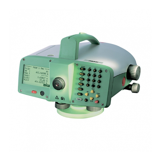
Page 11: Most Important Elements
On/ off button Most important elements Base plate Foot screws 12 13 Horizontal circle Lever to unlatch battery Battery compartment Button to unlatch card compartment cover Card compartment cover Display 10 Circular level 11 Hand grip with aiming sight 12 Ocular 13 Keyboard 14 Objective 15 Battery GEB111 (optional) - Page 12 Vertical axis tilt Compensator DNA03_05 DNA03_06 After centering the circular level the instrument is The compensator corrects for the vertical axis tilt on almost horizonal. A minimal instrument tilt remains, the line-of-sight so that the instruments aim is exa- this is the vertical axis tilt. ctly horizontal.
- Page 13 Collimation error α DNA03_07 The Collimation error (α) is the vertical angle bet- ween the actual line-of-sight and the ideal horizontal line. It is determined by a level test.
-
Page 14: Measurement Values
Staff height foresight. for double Measurement values observations: F1, F2 Staff height intermediate sight / set out sight Backsight-distance Foresight-distance Intermediate sight distance/ set out sight distance Starting point height, e.g. as height above HCol sea level Height of foresight point/ intermediate point Height difference between backsight and H=0.0000m foresight/ intermediate sight/ set out sight... -
Page 15: Applications
DNA10 for levellling and regulations within the given coun- Mainly for technical levelling tasks. tries apply as for optical levelling. DNA03 Adhere to the following general rules: Technical levelling and precision levelling. • Maintain same target distance for back and foresight. - Page 16 • Precision Mode: "Precise" is activated in the increase measuring accuracy. Activating tolerance-settings for line levelling, the Precision Mode for line levelling with typical instrument monitors the distance of the height accuracy is possible hut not necessary. reading (Ziellinie) to both ends of staff, top and bottom.
-
Page 17: Area Levelling
Area levelling Unlike line levelling, the individual target distances in area levelling may be very different. Depending on the required accuracy, a possible line-of-sight error or the influence of the earth’s curvature may have be taken into consideration. In strong sunlight and when working for long periods, cover instrument and stand with an umbrella. -
Page 18: Computer Software Package Leica Geo Office (Lgo)
• Data Exchange Manager Data exchange of fixed points, measurements, LEICA Geo Office (LGO) is available as a separate code lists and data output formats between the software package and includes the basic module as instrument (internal memory) and the computer. - Page 19 • Creating and adjusting1D height grids. Further information on the LGO will gladly be given by your local Leica representative. Data flow: We recommend using the XML-format to transfer measurement data from the DNA to the LGO and its We advise against transferring measured data in modules.
-
Page 20: Pcmcia Or Cf Card
PCMCIA or CF card Measured data is stored in the internal memory of the DNA03/ DNA10 and remains there. In addition, data can be backed up to a PCMCIA or CF card from the internal memory. The system supports the PCMCIA standard for ATA-Flash, SRAM or CF memory cards. -
Page 21: Equipment
Unpack Equipment Instrument Unpack the levelling instrument from the case and Charger with accessories (optional) check for completeness. Lemo-0/ RS232 data cable (optional) Allen key (2x) Battery GEB121 (optional) Memory card Lense hood (optional) Battery GEB111 (optional) Rain cover 10 User Manual, CD-ROM DNA03_03... -
Page 22: Batteries
Use the Leica Geosystems batteries, char- gers and accessories or accessories recommended by Leica Geosystems to ensure the correct functionality of the instrument. DNA_GEB GEB121... -
Page 23: Batteries
Batteries Removing the batteries Inserting the batteries DNA_BTTR_1 DNA_BTTR_2 First insert battery towards the objective (contact Place one of your hands below the open battery in a). Then pull the lever towards the display, press compartment to catch the battery and with the other battery upwards until it locks in place. -
Page 24: Memory Card
Only use clean and dry cards. Only insert or eject the card with the instrument off. DNA03_PCMCIA_1 Insert card with the Leica logo facing up until it locks in at the end position. Check: the card's eject button is flush with the card. -
Page 25: External Power Supply
The cable used must have a ferrite core (electroma- gnetic compatibility, EMV). Always plug the Lemo-plug with the ferrite core into the instrument. Only plug in or remove the plug when the instrument is switched off. Cables delivered by Leica Geosystems come standard with a ferrite core. Ferrit_01... -
Page 26: Measurement Preparations
Measurement preparations DNA03_Stativ2 DNA03_Stativ3 Level the tripod plate as much as possible. The remaining tilt of the tripod plate will be compensated with the foot screws on the instrument. DNA03_Stativ1 Loosen screws of tripod legs and pull them out to the required length and tighten screws. To guarantee a firm foothold, press the tripod legs firmly into the ground. -
Page 27: Levelling Up
Levelling up DNA03_Stativ4 NA03_Stativ5 Handle the tripod with care: • Check the fit of all screws and bolts. • During transport always use the cover supplied. • Only use the tripod for surveying. DNA03_Horiz_1 Place level on the tripod. Tighten tripod's central fixing screw. - Page 28 Centering the circular level NA03_Horiz_3 Turn foot screw C until the bubble is centered. DDNA03_Horiz_2 Position ocular above foot screw C. Turn foot screws A and B simultaneously in opposite directions until the bubble is in the center (of the imaginary "T").
-
Page 29: Focussing The Telescope
Focussing the telescope NDNA03_Monok_fok_l Aim telescope on staff using the coarse aiming NDNA03_Monok_fok_l device. Point telescope towards bright background (e.g. Turn focussing knob until image of staff is white paper). sharp. Moving the eye up and down behind the Turn ocular until reticle is focussed and appears ocular should not show the staff and reticle be sharp and black. -
Page 30: Centering
Centering Zentrier For possible centering over a ground point: Attach plummet. Loosen central fixing screw slightly and shift instrument parallel on the tripod until the plummet is exactly over the point. Tighten central fixing screw. -
Page 31: Measuring
Measuring General notices Height reading • First check and adjust the line-of-sight errors, Example of an optical rmeasurement: then the circular level on the instrument and then the staff. • Before starting work in the field • After long storage periods •... -
Page 32: Distance Measurement
Distance measurement Example of an optical measurement: DDNA_03_LatteF-Kreuz Focus with focussing knob. NDNADNA_Dist-Mess Fine aim with horizontal drive. Perform points 1 to 6 according to height readings. Check if bubble is centered . Reading Read height H at the middle line of the reticle. Distance line above: 2.670 m Example shown: H = 2.586 m... -
Page 33: Angle Measurement
Angle measurement DNA_Winkel-Mess The instrument is equipped with a rotatable horizon- tal circle. The angle unit is 360° subdivided into 1° intervals. The gon division is printed in steps of 50 gon below the 360° division. Angle conversion from degree to gon has to be done by the user. -
Page 34: Operating The Instrument
Operating the instrument The shown displays are examples and local software versions may deviate from the base version. DNA03_03 On switch: Press briefly Off switch: Press for 1 second Measure button Press lightly to trigger measurement. -
Page 35: Keyboard And Display
Focus Keyboard and display Black bar shows active field. Symbols Display key On/ off key Circular level Fixed keys (left row of keys) Keys with fixed functions. Fixed keys 2nd level Function is triggered with [SHIFT] plus fixed key. Entry keys <ENDE>... -
Page 36: Fixed Keys
INV, FNC, MENU, Lighting, PgUp, PgDn, <<Back, INS) and toggling numeric/ alphanumeric. Functions that support the measurements. Delete character/ field, Cancel/ stop MENU measurement. Confirm entry, continue to next field. Instrument settings, system-Information, line-of- sight check with collimator (DNA03 only). Display and circular level lighting. -
Page 37: Navigation Keys
PgUp Navigation keys "Page Up"= scroll up to previous "page" if display The navigation keys take on different functions, contains multiple pages. depending on the mode in which they are used: PgDn • Focus control • Cursor control "Page Down" = scroll down to next "page" if display •... -
Page 38: Entry Keys
Entry keys Enter numbers, letters and special characters. Enter decimal point and special characters. Toggle positive/ negative signs; enter special characters. In alphanumeric mode: • Quick consecutive presses call up the next sign (letter/ special character, number). • After a pause of approx. 0,5 seconds, the presently displayed sign is accepted and the cursor jumps to the next position. -
Page 39: Display Keys
<QUIT> Ends measuring program/ function. Para- Display keys meters entered are ignored. In MENU, PROG and DATA returns to selection menu. <QUIT> Leaves a sub program or an auxillary LINE LEV function; returns to initial display. ST.2 BACK PtID: <PREV> Reverts to last display. Rem : ------ <REC>... - Page 40 Symbols Numeric digits activated. Symbols with the following meaning are displayed α Alphanumeric characters activated. on the right side of the screen: Page number of the total pages or for QuickCode. QuickCode is activated when a search results the count of the counter codelist is loaded into the instrument and from the total sum.
-
Page 41: Navigating The Menus
Navigating the menus Illumination menu Switch on illumination, displays setting Example: Function menu [FNC] options. FUNCTIONS ILLUMINATION 1 TEST MEASUREMENT 1 All Off 2 VIEW MEASUREMENT 2 Displ+CircL: economic 3 CODE 3 Displ+CircL: permanent 4 PtID & INCREMENT 4 Circ.Level only 5 MANUAL INPUT <QUIT>... -
Page 42: User Input
2. Edit displayed value User input Edit a few digits of displayed value: Entering numeric values Highlight the desired entry field with the navigation keys. Numeric fields can only contain numeric values, negative signs and decimal points. Numeric fields Starts edit mode and places the cursor at are e.g.: starting heights, staff readings and the far right of the field. -
Page 43: Entering Alphanumeric Values
Entering alphanumeric values Inserting letters and numbers Alphanumeric fields can contain numeric as well as Inserting a digit into an existing number in alphanumeric values e.g.: PtID, Code, Attribute. edit mode. Procedure: A missing digit (e.g. -15 is entered instead of -125) can be inserted afterwards. -
Page 44: Deleting Letters And Numbers
Deleting letters and numbers Set of charaters Deleting single characters: Numeric digits Alphanumeric characters Deleting single characters in edit mode. Numeric Alpha 1 Alpha 2 Alpha 3 Alpha 4 Example: 1 AB & Deleting all characters: Press several times until entry field is empty. -
Page 45: Find Point
Signs Find point In the alphanumeric set of charaters, the "+" Find point is a global function to find internally and "-" signs are treated like normal stored measured points or coordinates. A point alphanumeric characters. They have no search may refer to a special job or to the entire mathematical function. - Page 46 Direct search: Search results: It is possible to search for a specific point number (e.g. "P13"). The search result contains all the points with the relevant point number. Example: Entry: P13 Two fixed points and three measurements are dis- played. Scroll through the found selection.
- Page 47 The Search function always finds fixed point (in The entered point number is searched for in the Fixed Points-jobs) before measured point (in Meas. memeory after confirming it with ENTER. The Jobs) that fulfill the search criterion. If several points search result is displayed in the dislog "Point are found that fulfill the search criterion, they are Search - Search Results"...
-
Page 48: Wildcard-Search
Wildcard-search Examples: finds all points of any given length. Wildcard-searches are characterized by the "*". The "*" serves as a wild-card for any given sequence of finds all points with the exact point ID "A". characters. finds all points of any given length that start Wildcards are used when the exact point ID is not with "A"... -
Page 49: Technical Hints For Measurements
Technical hints for measurements With other staff lenghts, measurements up to the Special measuring situations upper ends are not possible. Vibrations Code length required in the field of view Vibrations at the instrument, e.g. due to wind can be For exact measurements, the centering damped by touching the upper third of the tripod. -
Page 50: Important Instrument Settings
Using the integrated field level test procedure or should be activated for line levelling jobs that the laboratory test with the collimator require high accuracy.Further details are on (DNA03 only). See Check & Adjust, resp. check page 15. with collimator. Determine the values through your own measurements and procedures and enter them manually ([MENU]/ All settings/ System). -
Page 51: Measurement Modes (Mode)
Measurement modes (MODE) The instrument calculates the average of all measurements made. Set single or multiple measurements. With multiple • Median and amount of measurements to be measurements the instrument automatically carries made, e.g. n = 3 (2... 99). out several measurement in sequence until the defi- Uneven number of measurements: central ned amount of measurements are done, a termina- value... - Page 52 reached by eliminatig outliers (measurement At "n min" = "n max" no measurements are value with the greatest improvement). discarded by the wild shot test. Entries: • Repeat single n min Minimum amount of measurements "Repeat single measurement". The instrument (2..99) continuously makes single measurements n max...
-
Page 53: Measuring Progress
Measuring progress Staff Current staff height according to mode (mean, Different screens are displayed while the measure- median or single measurement) after "n" measure- remnts are in progress, depending on the measure- ments. ment mode selected. sDev Single measurement Current standard deviation of a single measurement Measurement time is very short. -
Page 54: Repeating A Measured Sight
If any other key is pressed [not the DATA key]: Repeating a measured sight the last valid single measurement is displayed: A sight just carried out can be repeated by pressing the <<Back key. In line levelling, several sights, but the entire station at most (B and F, resp. -
Page 55: Managing Point Ids
Managing point IDs Point IDs are handled differently if they are for line points (foresight), intermediate or setout sights. Line points (foresight) The instrument will suggest a running automati- cally incremented number as a foresight point ID. The starting point ID and the increment are defined in the function [FNC]/ "PtID &... -
Page 56: Data And Memory Management
Data and memory management Job: Job 1 Job 2 Job 3 Measure and Record The data is stored in jobs, comparable to direc- Line 1 tories.They can be copied, edited or deleted indivi- Line_01 dually. Line 2 Line_02 Within a job data is stored in two memory areas: Line 3 Measurement memory: Line_99... -
Page 57: Measure & Record
Measure & Record After start up, either the basic measuring program The procedure of MEAS & REC corresponds mostly "MEAS & REC" is called up or message is dis- to line levelling with the BF method . The first back- played. - Page 58 The point numbers are not automatically If the data back up settings in the menu is set to incremented in this dialog. If required, the "RS232" , then the data are transferred to the imter- numbers must be incremented manually. face in GSI-format and not saved internally.
-
Page 59: Starting Display (1St Backsight)
Starting display (1 backsight) Height of starting point (standard value = 0.00000). First enter all required values and then trigger the If the point is recorded in the list of fixed points of measurement with the measurement key. the job "Measure & Record", its height is automati- cally entered. -
Page 60: Foresight Display
Foresight display <REC> Save measurement and continue to backsight. First enter all required values and then trigger the measurement. <LAST> Data and measured values of the last backsight are displayed. MEAS & REC <END> PtFS: Quits the "Meas & Rec" program. As long as no Rem : ------ new line is started, the current line can always be... -
Page 61: Backsight Display
Backsight display H BS (height backsight), dH, Staf and Dist are displayed with corresponding vales. First enter all required values and then trigger the measurement. <REC> Save measurement and continue to foresight. <LAST> MEAS & REC Data and measured values of the last foresight are PtBS: displayed. -
Page 62: Surveying Intemediate Points
Surveying intemediate points Entries: There are two displays for the intermediate sight: Next: Enter the point number to be measured next. Point a) Height difference as related to the backsight (Pt numbers are sequential and are incremented with to BS) every measurement. - Page 63 Point-to-point Pt2: First enter all required values and then trigger the The point number of the current measured point measurement with the trigger key. dH2: The height difference from the current measured intermediate point to the last measured point. INTERMEDIATE (BS to Pt) Next: 1003 Pt2H...
-
Page 64: Set Out
Set out Entries: Normally, height values are staked out. These stake StkP: out heights can be loaded as fixed points into the Enter the running point number. The height of the entered point is searched for in the current job as corresponding job, in order for the heights to be cal- soon as the entry is confirmed with ENTER. - Page 65 Set out display Set out according to distance: Trigger measurement. The calculated values and cut are displayed. STAKE DISTANCE Set out according to height or height difference: PtBS: PtID: 1001 Rem : ----- STAKE HEIGHT SO D: 25.00 m PtBS: Dist: 24.85 m StkP:...
- Page 66 Procedure within the set out display Move staff and repeat measurement until the diffe- rence (fill/ cut, in/ out) meets the cut. Then select one of the three functions: <REC> Store measurements and results, with the possibility of subsequent measurements. <NEXT>...
-
Page 67: Functions (Fnc)
Functions (FNC) [FNC] opens the main menu for functions that sup- Example: port measurements: Place the function " View measurement " in the [USER]-key if you want to frequently inspect the results of measurements. FUNCTIONS 1 Test Measurement 2 VIEW MEASUREMENT 3 CODE 4 PtID &... -
Page 68: Test Measurement
Test measurement View measurement "Test measurement" provides a measurement dis- This function displays the result of the last measure- play, in which as many measurements as desired ment made again. can be made without storing the data. This mode is Calling up the "View measurement"... -
Page 69: Code
Code Example: Code entered manually (no code list available): This function permits a code to be entered Two entry modes are available: Select a code from the code list. A code would CODE & ATTR ENTRY have to be stored in the instrument. If no code list is stored then the second mode is Code : ------... -
Page 70: Point Id And Increment
Point ID and increment Manual entry of measured values Enter starting value for the running point ID and Electronic measurements to staff less than 1.8 m enter the increment. away are not possible. These measurements must be done optically and the data entered into the Call up the function instrument manually. - Page 71 Calling up the "Manual input" function: MANUAL INPUT Staff: 0.00000 m Dist : 0.00 m <QUIT> <CONT> DNA-Dde 24 This function is blocked in the level test measuring program.
-
Page 72: Start Programs
Start programs The following start programs are available as measuring programs in [PROG]: LINE LEVELLING 1 Job DEFAULT Meas & Rec Line levelling Level test 2 Line : LINE00002 (BF, aBF, BFFB, aBFFB) 3 Set Tolerances 4 Start/ CONT Set job Set job Set job <END>... -
Page 73: Set Job
Set job If no job was created, then the "DEFAULT" job is NEW JOB automatically suggested. If several jobs are availa- ble, the desired one can be selected. Job : ------ Oper: ------ Cmt1: ------ SELECT JOB Cmt2: ------ 1/1) 20.06.2006 10:00:03 Job :... -
Page 74: Set Line
Set line NEW LINE In the selected job, a new line name is automatically created and displayed. Should a different line name Name: LINE00003 be desired, then it has to be changed before starting Meth: with the measurement. If the job is empty, then a PtID: new line is switched to. - Page 75 After entering the start PtID the job checks if it is <PtSearch+> already stored as a fixed point, measured point or Extented point search, including other jobs. as a previous start PtID (manual input/ standard If the point is not found in the memory, even with the value).
-
Page 76: Set Tolerances
Set tolerances tion) to both ends of staff, top and bottom. The redu- ced number of staff code elements may slightly Set tolerances must be adhered to during line level- lower the measuring accuracy of measurements ling, depending on the application. Tolerance taken on the edge of the staff. - Page 77 MaxDist Change tolerances Maximum target distance. To check or change tolerance values open the dis- play as follows: StafEnds: Enables lowest or highest approach to the ends of <VALUE> the staff. Branches to the entry of tolerance values: • BFFB, aBFFB method: ENTER TOLERANCES TDistBal: 3.00 m...
-
Page 78: Select Method
Select method Check list Select level test procedure. With the measuring programs Meas & Rec and Line Levelling, after starting a new line, the first thing displayed before starting the measurement is SELECT METHOD a check list with important settings. To change the settings, call up the corresponding function. -
Page 79: Start Programs Error Messages
Start programs error messages The error messages are self explanatory. The countermeasures can usually be derived. Message Explanation / Counter measure Memory is full! Create space - delete an existing job. Job exists in memory Enter a different job name. Invalid job name! Name is empty or reserved for the system! Line exists in the job! -
Page 80: Measurement Programs
Measurement programs The contents displayed, especially the rows, may Introduction differ in local software versions. The functions however, are always the same. As opposed to the simple measuring program Meas & Rec, the display switched automatically to the PROG, MENU and DATA next screen in the measuring programs Line- These functions can be called up from the basic Levelling and Level Test. -
Page 81: Line Levelling
Line levelling PROGRAMS The line levelling measuring program supports the BF, aBF, BFFB and aBFFB method that are select- 1 MEAS & REC able in the "Set line" start program. 2 LINE LEVELLING 3 LINE ADJUSTMENT Meaning of the methods: 4 CHECK &... -
Page 82: Typical Measurement Display Of Line Points (B/ F)
Typical measurement display of PtID PtID of next aiming (can only be edited in foresight). Line points (B/ F) Remarks to the next measurement (optional). LINE LEV dH T ST.4 Total height difference between currrent backsight PtID: and starting point. Rem : ------ dH T:... -
Page 83: Last Measurement Backsight
With the help of the current station number Last measurement backsight and the indicator arrow, it can be <LAST> determined if you are on an even or uneven Example for BF method: numbered station. This information is helpful, if you Displaying measured values with the instruments have to close line levelling with a even station height of collimation:... -
Page 84: Last Measurement Foresight
Last measurement foresight Intermediate sight and set out Calculations of the intermediate sight and set out <LAST> always reference the last backsight. With the BF Example for BF method: method switching between intermediate and set out Measured values displayed with height difference sight is permitted in any sight (B/F). -
Page 85: Station Results
be measured, the intermediate and stakeout sights Station results for the current station must be measured at this time 'When using the double sight procedure (BFFB, before the first measurement of the next station is aBFFB) at the end, after completing the 4th measu- made. -
Page 86: Exceeding Tolerances
<STATION> Page 2: Switches to station results, page 1. STATION RESULTS STATION RESULTS Stat.No : StatDist: 30.55 m Stat.No : B1-B2 -0.0200 m StatDif : -0.0200 m F1-F2 0.0000 m ΣStatDif: 0.0080 m -0.7900 m <CONT> 282.5023 m <PREV> DNA-Dde 43 DNA-Dde 42 Stat.No Stat.No... -
Page 87: Line Cut
Example: Line cut Distance balance tolerance was exceeded: With all methods of the program line-levelling, there is the possibility of comparing the height of the last DISTANCE BALANCE CHECK point of a line with a known fixed point and to calcu- late the misclosure. - Page 88 LINE INFO QUICK CLOSURE Line: LINE225 LstId: #Stations: Hline: 412.7359 m dH T: 0.5100 m PtId : DTot: 96.90 m H fix: 412.0000 m TBal: -0.70 m Diff : -0.7359 m <QUIT> <CONT> <END> <PtSearch> <REC> #Station.:total number of stations <PtSearch>...
-
Page 89: Line Adjustment
Job: Line Adjustment to select a job containing level lines. The line adjustment program allows adjusting single Line: level lines. Any two points of the line can be defined to select a level line in the current job. Lines recor- as control points. - Page 90 Adj.: Fixpoint 2: Three different point types and some combinations Default for FixPoint 2 is the last point of the se-lec- of them can be selected: Line-, Intermediate- and ted line. Any point of the line can be selected as StakeOut-points.
- Page 91 Close: <RUN> Calculated misclosure of the line at the second Fix- to adjust and record all points of the selected point- Point. types. Tol.: Calculated closing tolerance according to the se- lected method. /Sta.: Calculated misclosure per station. Meth.: Method used for the adjustment, in this example "by Distance".
-
Page 92: Data-Management
Data-Management • new: the adjusted height The original measurements are kept in the job. With • ori: the original measured height every adjustment, a new data-block with all new point-heights is recorded in the current job. Resid: Residual or difference between H new and H ori. The calculated heights can be viewed using the on- board data manager. -
Page 93: Check & Adjust
The sequence of the staff to be measured (A1, B1, Check & Adjust B2, A2) must be adhered to in all four procedures: With the Leica DNA03/10 the optical as well as an Station 1 A1, B1 electronic collimation error can occur. - Page 94 Data storage: Level test measurements are stored in a special line of the selected job. The line name is predetermined and is called "Check & Adjust" . Should the level test result in a line-of-sight error >100", an error message is displayed. With the "A x Bx"...
-
Page 95: A X Bx" Method
"A x Bx" method From the center procedure: Instrument positioned in the center of the staffs and close to staff B (inside or outside). a = approx. 30m. min. 2.5 m DNA03_Nivellierprobe_1 Position Position Staff A Staff B Conditions on the distances: 1. - Page 96 Kukkamäki procedure: Instrument positioned in the center of the staffs and on the outside of staff B at a distance b (b = a). a = approx. 20 m. Distance conditions as before. DNA03_Nivellierprobe_2 Position Position Staff A Staff B...
-
Page 97: A X X B" Method
"A x x B" method Features of this method: The distances have a 1:2 ratio in every position. Förstner procedure: Instrument positioned at each third between the staffs. Staff distance D approx. 45 m - 60 m. Distance conditions: 1. Station: 0.2 x D < Dist_A1 < 0.4 x D 2. - Page 98 Näbauer procedure: Instrument position outside of the staffs. a = approx. 15 m - 20 m. Distance condition: same as above. DNA03_Nivellierprobe_5 Position Position Staff A Staff B...
-
Page 99: Measuring Procedure
Measuring procedure A1, Dist Displays the measurement A1 The program shows which station is to be placed where using self explanatory displays: B1, Dist Displays the measurement B1 (in this display not Procedure: taken yet) • Trigger measurement. Repeated <CONT> measurements can be made. - Page 100 Difference Difference of the two collimation errors. Reticle Final value for staff A. For adjusting the reticle see section Check & Adjust. <SET> The new collimation error is stored in the system as corrective value. <QUIT> The old collimation error remains set. The <<Back-function is blocked.
-
Page 101: Coding
"Desc" of each measuring display. Attr1 *) Attribute value 1 Coding with the code list A code list can be created in the Leica Geo Office program with the Code List Manager and then Attr8 *) Attribute value 8 loaded into the instrument. It also contains the follo-... -
Page 102: Entering A Code
Coding without code list Entering a code Coding without code list is the same as the form of coding in GSI-format known from the old generation • Codes are entered in FNC (see section Code). of instruments. • Should no code list exist then the prompt for a The elements are: manual input appears automatically. -
Page 103: Quick Code
The codelist consists of a maximum of 200 codes and can be created in Leica Geo Office with the Codelist manager or entered directly into the instru- ment in reduced form. Whether using the Codelist... - Page 104 instrument requires assigning a two digit number (the Quick-Code nummer) to the codes. Codes wit- hout a Quick-Code number are automatically assi- gned the next highest free Quick-Code number 01, 02, 03, ... 99, 00.
-
Page 105: Menu Settings
Menu settings The contents of the following display, especially the 2 ALL SETTINGS rows, may differ with local software versions. The 1 System respective functions remain the same. • Beep • Initial data In MENU instrument settings are made. • Auto-OFF [MENU] opens the main menu. - Page 106 Free jobs USER-key Battery Instrument temperatue DNA-Dde 53 Display heater Select appropriate setting from the list. Collimation error <SET> Software version Accept and store new settings. 4 CHECK WITH COLLIMATOR <QUIT> Measuring program (DNA03) Quit display, possible setting changes are ignored.
-
Page 107: All Settings
• Standby (Sleep) All settings The instrument switches into energy saving mode about 15 minutes after the last key press. System At the next key press it reverts to normal mode. Contains the system settings. Contrast Beep Sets contrasts in steps of 10%. Acoustic signal trigger key: USER-key Off, loud, normal. -
Page 108: Measuring
Display heater Measuring When the instrument is switched on the display Important settings for measuring. heater is set to Off. Set code • Refers to Quick code. Display heater starts when the inner temperature of • Before the instrument falls below -5°C. Stores code before making a measurement. -
Page 109: Communication
Communication parameters of the RS232 interface • GSI-8 for data transfer between computer and instrument. 8-data characters output format Leica standard settings (83..00+12345678). 19200 baud, 8 data bits, no parity, CR/LF, 1 stop bit. These data words can hold alpha as well as Baudrate numeric data. -
Page 110: Unit Selection
Unit selection • CR/ LF Distance New line and line feed. Meter Meter • US foot US foot New line. INT foot International foot Stop bit US foot/ inchUS-foot-inch (DNA03 only) Set to 1. Temperature °C Degree Centigrade °F Degree Fahrenheit... -
Page 111: Date And Time
Date and time System information Display and setting of system date/ time. After date Display important and useful information. and time have been entered, they are stored in the system. Free jobs Amount of free jobs (maximum 16). Date Format:dd/mm/yy (day,month, year) USER-key Current assignment of the USER-key. -
Page 112: Check With Collimator
Check with collimator Procedure: [MENU]/ Testing with the collimator: The measuring program, only available with the DNA03, contains electronic collimation error deter- mination using a collimator. Reticle adjustment (optical collimation error) is not supported. The special collimator contains a graticule with a reticle with the scale of the digital level and is used to make the adjustments. - Page 113 <CONT> Distance Confirm and continue to measurement display. Distance. Coll.err.old Old collimation error. Coll.err.new New collimation error. <SET> Store new collimation error. DNA-Dde 55 Procedure: [MODE] All the measuring modes that are also vailable with the staff. Aim at and focus on the bar code of the staff. Trigger measurement with the measurement key or with the external command (GET/M/WI32/WI330).
-
Page 114: Data Manager
Data manager Use the data manager to enter, edit, view or copy Points 1-3 refer to the internal memory. The corre- data to other data mediums. It manages the internal sponding functions referencing the storage card can memory, where all measured data is stored and the be found under <CARD>. -
Page 115: Card Functions
1. Page: Card functions Dir. Directory of the card. Insert or delete data on the Size PCMCIA-card or format the card: File size in KB. / <CARD> calls up the card display: Free Free memory space on the card in KB. 2. -
Page 116: View /Edit Data
Measurements View /edit data Measured data in memory can be searched, dis- Call up "View / Edit data": played and partially deleted. First, enter search cri- teria of the job, line and point. VIEW / EDIT DATA MEASUREMENTS 2 IMPORT FIXPOINTS JOBS 4 CODELIST <QUIT>... - Page 117 <VIEW> <DEL> Point search starts and result is displayed: Deletes record (necessary records for line calcula- tion can not be deleted). <SEARCH> VIEW Returns to data search display ready for the entry of Class:Meas Meas&Rec new search criteria. PtID : ------ More information on the structure of data block is in Back :...
-
Page 118: Fix Points
Fix points Display: A fix point must contain either all coordinates (E, N, PtID H) or only height (H). Lists the found points. E/N/H Point coordinates. With height points only enter the height. <DEL> Delete single points. <NEW> Enter new point (PtID and height with or without position coordinates). -
Page 119: Code List
Code list <NEW> Enter a new code: Find, display and supplement data in the code list. It is possible to scroll through the code list from the main display. The code has a maximum of eight INPUT CODELIST attributes. The information 1-8 on a code extend over two pages. -
Page 120: Delete Memory
Delete memory <DEL-ALL> Deletes entire memory. After confirming the ques- Deletes all measurements or fix points of a job, tion whether to delete, all records are deleted. deletes an entire job or the entire memory: DELETE DATA / JOBS Job : DEFAULT Data: Measurements... -
Page 121: Memory Information
FixPoints Memory information Amount of strored fix points in the job. Provides information on contents (sectors for mea- Free Jobs surements or fix points) of individual jobs and the Displays the amount of free jobs available if only number of free jobs available: measurements were stored. -
Page 122: Data Export
DNA-Dde 66 additional user formats. Create and load the user Target formats with the Leica Survey Office program. Select memory target (card or serial interface). Target directory on card: GSI-Formats: \GSI Select job. - Page 123 Start data export. If the device receiving the data is too slow, data loss may occur as transfer is done without protocol. Further information on data flow can be found in the section "Computer software package Leica Geo Office (LGO)".
-
Page 124: Data Import
Dir. Data import Card directory. Loading fix points or code list from the memory card Data into the internal memory of the instrument. Existing Data file was created. data is completely replaced by the new data. Fixed <OK> points and code lists must be in GSI-format. Confirm and continue. - Page 125 File Displays the file for checking. <IMPORT> Start data import. <NEWJOB> Create new job.
-
Page 126: Data Storage
Data storage The internal memory stores data by jobs. However, Start programs fix points and measurements are stored seperately. Data blocks of different sizes are created, depen- = Job name ding on the measuring program. The data is stored Oper = Operator name right after the completion of an action. -
Page 127: Measurement Program
Measurement program Measurement PtID = Point number Start PtID = Remarks PtID = Point number Back/... = Staff height (Back/B1/B2/Fore/F1/F2/ = Coordinate (Eastings) Intm/ SOut/ Meas) = Coordinate (Northings) Dist = Horizontal distance = Height Type = Measurement/ manual input Type = Type of point (fix point/ entered = Height difference refering to backsight... -
Page 128: Measurement Mode And Corrective Parameter
Target point Measurement mode and corrective PtID = Point number parameter = Coordinate (Eastings) These data blocks are stored at the beginning of a = Coordinate (Northings) new line, even when a setting is changed during a = Height measurement. = Remarks Measurement mode Date... -
Page 129: Coding
Coding Fix points coordinates Coding with code list PtID = Point number = Coordinate (Eastings) Code = Code name = Coordinate (Northings) Desc = Description = Height Attr1 *) = Attribute name 1 … Attr8 *) = Attribute name 8 *) Instead of attr1... -
Page 130: Rs232 Interface
RS232 interface Measuring via serial interface RS232 is only possi- ble in the basic measuring program "Meas & Rec" and only in the GSI-format. Set data output to RS232 ([MENU]/ All settings/ System) and select GSI-8 or GSI-16 format ([MENU]/ All settings/ Measuring). -
Page 131: Safety Directions
Safety Directions The following directions should enable the person Intended use of instrument responsible, and the person who actually uses the instrument, to anticipate and avoid operational Permitted uses hazards. The person responsible for the instrument • Electronic and optical height and distance must ensure that all users understand these direc- measurements to a staff. -
Page 132: Adverse Uses
Suitable for use in an atmosphere appropriate for • Use with accessories from other manufacturers permanent human habitation. Not suitable for use in without the prior express approval of Leica aggressive or explosive environments. Use in rain is Geosystems permissible for limited periods (spash-water-proof). -
Page 133: Responsibilities
To understand the safety instructions on the Leica Geosystems AG, CH-9435 Heerbrugg, her- product and the instructions in the user manual. einafter referred to as Leica Geosystems, is respon- • To be familiar with local regulations relating to sible for supplying the product, including the user safety and accident prevention. -
Page 134: Hazards Of Use
Strong magnetic fields in the immediate vici- Using a battery charger not recommended by nity (e.g. transformers, melting furnaces...) may Leica Geosystems can destroy the batteries. This influence the compensator and lead to measuring can cause fire or explosions. errors. - Page 135 DANGER CAUTION Because of the risk of electrocution, it is very Be careful when pointing the product towards dangerous to use poles and extensions in the vicin- the sun, because the telescope functions as a mag- ity of electrical installations such as power cables or nifying glass and can injure your eyes and/or cause electrical railways damage inside the product..
- Page 136 Adhere to the instructions given by the computer Avoid subjecting the product to mechanical stress. manufacturer with regard to field use in conjunction CAUTION with Leica Geosystems instruments. When using a vertical staff supported by one CAUTION brace there is always the danger of falling (e.g. by...
-
Page 137: Electromagnetic Compatibility (Emc)
WARNING Product specific treatment and waste management information can be downloaded from the Leica Geo- If the product is improperly disposed of, the systems home page at http://www.leica-geosys- following can happen: tems.com/treatment or received from your Leica • If polymer parts are burnt, poisonous gases are Geosystems dealer. - Page 138 Although the product meets the strict regulations and standards which are in force in this respect, and standards which are in force in this respect, Leica Geosystems cannot completely exclude the Leica Geosystems cannot completely exclude the possibility that other equipment may be disturbed.
-
Page 139: Fcc Statement, Applicable In U.s
Changes or modifications not expressly This equipment generates, uses and can radiate approved by Leica Geosystems for compliance frequency energy and, if not installed and used in could void the user's authority to operate the equip- accordance with the instructions, may cause harm- ment. -
Page 140: Product Labelling
Product labelling Type: DNA 03 Art. No. 723289 S. No.... Power: 12/6V -, 0,1Amax Leica Geosystems AG CH-9435 Heerbrugg Manufactured 2002 The device complies with part 15 of Made in Switzerland the FCC rules. Operation is subject to the following two conditions:... -
Page 141: Care And Storage
Care and storage Transport Always make sure that • the instrument is transported in its transport Always use Leica Geosystems original case to case transport the instrument. (Transport case and shipping container). Check the field adjustment parameters specified in this manual after long storage or transport periods. - Page 142 Never transport the instrument loose in a vehicle. For shippping by train, plane or ship always use Shocks and vibrations may damage the instrument. the Leica Geosystems original packaging Always transport the instrument secured in the (transport case and shipping container) or other sui- casing.
- Page 143 Storage F° C° Lagerung Koffer_gedreht Keep an eye on temperature limits when If the instrument gets wet remove it from storing your euipment, especially in the case, clean and dry it. Do the same with summer inside a vehicle. the conainer, foam insert and accessories (at most at +40°C/ +104°F).
- Page 144 Cleaning Do not use aggressive liquids, as they may damage the plastics parts. Casing, keypad and display: Only clean them with a clean, soft cloth and if necessary dampened with a small amount of suds. Objective and Ocular: •Blow dust off the lense. •Do not touch the glass with your fingers.
-
Page 145: Check And Adjust
Check and adjust Stand Circular level Dosenlibelle_1 Stativ_just The individual elements must be firmly connected Level instrument together. Turn instrument by 180°. Center bubble if it extends beyond the centering Firmly tighten Allen screw (2) (if one is used). circle. Tighten the joint on the stand head (1) just enough so that with the legs extended, the stand can be lifted off the ground and the legs... -
Page 146: Reticle
Reticle Dosenlibelle_2 Correct half of the error with the Allen key. Fadenkreuz If the collimation error exceeds 3mm per 30m, the Repeat steps 1 to 4 until the circular level bubble is collimation needs to be adjusted. centered at any random telescope pointing. Marked screw may not be used to adjust Turn Allen key until design value is reached. -
Page 147: Technical Data
Height measurements Opening angle 2° Standard deviation per km double run Field of view 3.5m at 100m (ISO 17123-2): Min. target distance 0.6m Electronic measurement DNA03 DNA10 Multiplication constant with invar staff 0.3mm 0.9mm Addition constant with standard staff 1.0mm 1.5mm... - Page 148 Heating on/off switch, sets in below -5°C Data backup PCMCIA-card (flash, SRAM), Dimensions up to 32MB capacity Instrument Temperature range Height (incl. hand grip) 168mm +/-5mm Storage: -40°C - +70°C Width Operation -20°C - +50°C on the side drives 240mm Environmental conditions instrument body 206mm...
- Page 149 Powered via serial interface Voltage range using an external cable 11.5V - 14V (DC) Current consumption at 12V • maximum 500mA • Instrument on and without lighting, typically: 70mA...
-
Page 150: Corrections/ Formulas
Corrections/ formulas Height differences d1, d2, d3, d4 = distances of the respective dH = height difference of all sights in relation to staff heights. back sight. Distance balances Σ Σ dh = height difference of two successive measured D Bal = points from the first measurement after the back =back sight distance sight. -
Page 151: Accessories
Accessories Tripod Staffs ground plate of staff struts Power supply batteries charger Recording PCMCIA-card Computer cable - serial interface Computer software Leica Geo Office LevelPak-Pro Documentation User Manual Field Manual GSI Online... -
Page 152: Sensor-Error Messages
Sensor-error messages List of the "Measurement not possible" messages: Error message Counter measure Image too dark. Light up staff. Image too bright. Darken staff or reduce lighting to staff. No staff or staff covered or insuff. code length. Check targeting. Distance out of measuring range. -
Page 153: Index
Index Symbols Check with collimator ....... 106, 112 Circular level ..........28, 145 "A x Bx" method ..........95 Code ..............69 "A x x B" method ..........97 Code list ........... 101, 119 Coding ............101, 129 Accessories ............151 Collimation error .......... - Page 154 Decimals ............108 FNC ..............67 Delete memory ..........120 Focus ............35, 50 Display heater ..........108 Focussing knob ..........29 Display key ............35 Focussing the telescope ........29 Display keys ............39 Formulas ............150 Distance measurement ......32, 147 Förstner ..............
- Page 155 Measuring at the beginning of the staff ....49 Kukkamäki ............96 Measuring at the upper end of the staff ..... 49 Measuring procedure ......... 99 Leica Geo Office ..........18 Measuring progress ........... 53 Level lighting ............36 Menu settings ........... 105 Levelling up ............
- Page 156 Precision levelling ..........15 Symbole ............... 3 Symbols ............3, 40 System information ........106, 111 Quick code ............103 Quick settings ........... 105 Technical data ..........147 Temperature range .......... 148 Record ..............57 Temperature, unit ..........110 Repeating a mesaured sight ......54 Test measurement ..........
- Page 158 International Standards of Quality Management and Quality Systems (ISO standard 9001) and Environmental Management Systems (ISO standard 14001). Ask your local Leica dealer for more information about our TQM program. Leica Geosystems AG Heinrich-Wild-Strasse CH-9435 Heerbrugg Switzerland Phone +41 71 727 31 31 www.leica-geosystems.com...
Need help?
Do you have a question about the DNA03 and is the answer not in the manual?
Questions and answers