Table of Contents
Advertisement
A. Raw Data ................................................................................................................ 9-2
B. Equipment .............................................................................................................. 9-2
1. Instrument and Tripod Setup............................................................................... 9-3
C. Level Operation...................................................................................................... 9-4
1. Job Setup ............................................................................................................ 9-4
D. Collimation Error Correction ................................................................................ 9-9
E. Check and Adjust Procedure .............................................................................. 9-10
1. A x Bx Method................................................................................................... 9-12
2. A x Bx Method................................................................................................... 9-19
F. Line Leveling ........................................................................................................ 9-23
1. Setup ................................................................................................................ 9-23
2. Starting the Run ................................................................................................ 9-28
3. Check Shots...................................................................................................... 9-34
G. Allowable Misclosure .......................................................................................... 9-37
H. Transferring Data ................................................................................................. 9-40
I. Warning Messages ................................................................................................ 9-40
1. Meas. below limit! ............................................................................................. 9-41
2. Distance Bal. too big! ........................................................................................ 9-43
3. Meas. Dist too big! ............................................................................................ 9-44
Chapter 9
DNA 10 Digital Level
Table of Contents
Advertisement
Table of Contents

Related Manuals for Leica DNA 10


Summary of Contents for Leica DNA 10
-
Page 1: Table Of Contents
Chapter 9 DNA 10 Digital Level Table of Contents A. Raw Data ........................ 9-2 B. Equipment ......................9-2 1. Instrument and Tripod Setup................9-3 C. Level Operation...................... 9-4 1. Job Setup ......................9-4 D. Collimation Error Correction ................9-9 E. Check and Adjust Procedure ................9-10 1. -
Page 2: Raw Data
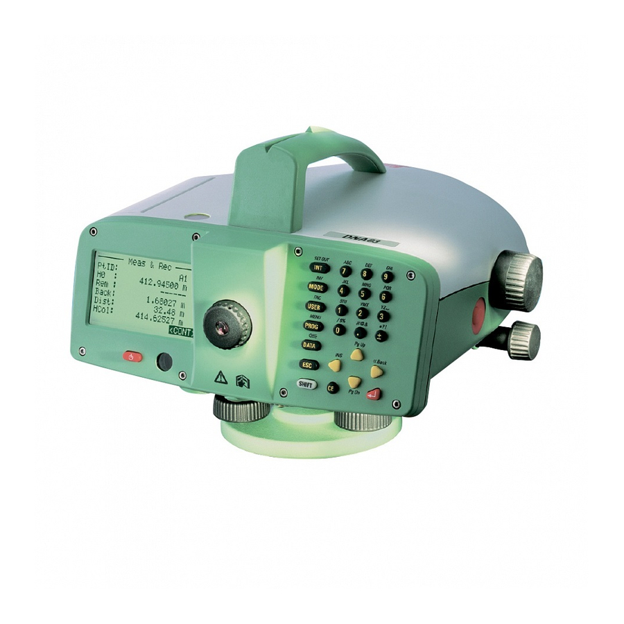
DNA 10 Digital Level 9. DNA 10 Digital Level The Leica DNA 10 level is the latest digital level utilized by WYDOT. These levels began replacing the older Leica NA2002 digital levels in 2004. There are several advantages inherent with digital levels: ... -
Page 3: Instrument And Tripod Setup
Chapter 9 Fixed-legged tripod. Bar-coded level rod. Field book. Temporary turning platform (turtle). 1" x 1" wooded hubs or railroad spikes (used for the peg test). 1. Instrument and Tripod Setup As shown if Figure 9-2, place the digital level on the tripod and tighten the central fixing screw to securely fasten the level to the tripod. -
Page 4: Level Operation
DNA 10 Digital Level C. Level Operation 1. Job Setup Turn on the DNA 10 by pressing the on/off button, indicated by the red arrow. Figure 9-2. On/off button After the level is turned on, the MEAS & REC screen will be displayed. - Page 5 Chapter 9 To start a new job press the PROG button (red oval). Figure 9-4. Program and enter Buttons. When the PROGRAMS menu is displayed, use the yellow navigation buttons (red oval in Figure 9-6) to scroll down to option 2, LINE LEVELLING. Press the red Enter button (red square in Figure 9-4) or just press the 2 button (red circle in Figure 9-6).
- Page 6 DNA 10 Digital Level Figure 9-6. Navigation buttons. At the LINE LEVELLING menu, create a new job. Highlight option 1, Job and press the Enter button or press the 1 button. Figure 9-7. Line leveling menu. Revised December, 2012...
- Page 7 Chapter 9 At the NEW JOB menu, type in the job name (up to 16 characters). Use the white SHIFT button (red oval in Figure 9-9) to alternate between numerical digits and alphabetical letters/ special characters. After typing the job name, press Enter and type in the operator’s name or initials then press Enter again.
- Page 8 DNA 10 Digital Level Use the navigation buttons to scroll down to highlight SET, then press Enter. The message "Job Set!" will be briefly displayed. Figure 9-10. New job settings. To open an existing project from the LINE LEVELLING menu (see Figure 9-7), choose option 1, Job and press the Enter button.
-
Page 9: Collimation Error Correction
Figure 9-13. Collimation error. With the DNA 10, optical and electronic collimation errors can occur. Staff readings are automatically corrected for the electronic collimation error and stored in the instrument. Optical collimation errors are eliminated by adjusting the reticle (cross-hairs) with the ocular (eye-piece). -
Page 10: Check And Adjust Procedure
DNA 10 Digital Level E. Check and Adjust Procedure At the PROGRAMS menu, highlight option 4, CHECK & ADJUST and press the Enter button. Figure 9-14. Check & Adjust. In the CHECK & ADJUST menu, the job that was previously created should be active. Highlight option 2, Meth. - Page 11 Chapter 9 Use the left or right navigation arrow buttons to select A x x B or A x Bx. Figure 9-16. Select peg test method. Once the peg test method has been selected, use the up and down navigation arrow buttons to scroll down and highlight SET.
-
Page 12: A X Bx Method
DNA 10 Digital Level At the CHECK & ADJUST menu, highlight option 3, START and press the Enter button to begin the two-peg test. Figure 9-18. Start the peg test. 1. A x Bx Method Pound a 1" x 1" wooden hub or railroad spike in the ground at stations A and B. The distance between A and B is approximately 30 meters. - Page 13 Chapter 9 For the first set of measurements, the instrument is setup at position 1 while the level rod is set on a hub or spike at station A. At the CHECK & ADJUST screen, press the Enter button to continue. Figure 9-20.
- Page 14 DNA 10 Digital Level To take the first measurement, press the red measure button on the right side of the instrument (indicated by the red arrow in Figure 9-21). The DNA 10 will average three readings for each measurement. Figure 9-22. Ready for measurement.
- Page 15 Chapter 9 For the second measurement, the instrument remains at position 1 while the level rod is moved to a hub or spike at station B. Figure 9-24. Ready for measurement. After the second measurement has been taken, record the rod reading and distance for B1 in the field book.
- Page 16 DNA 10 Digital Level When the CHECK & ADJUST screen is displayed, move the instrument to position 2 while the level rod remains at station B. Press the Enter button to continue. Figure 9-26. Second two-peg test setup. The instrument is now ready for the second set of measurements.
- Page 17 Chapter 9 After the measurement has been taken, record the rod reading and distance for B2 in the field book. Accept the measurement and continue by pressing Enter. Figure 9-28. First measurement. For the second measurement, the instrument remains at position 2 while the level rod is moved to station A.
- Page 18 ± 15". If the difference is greater than ± 15", then another peg test will need to be performed. If the 2nd peg test is still greater than ± 15", the instrument may need to be calibrated by a Leica technician.
-
Page 19: A X Bx Method
Chapter 9 2. A x Bx Method Pound a 1" x 1" wooden hub or railroad spike in the ground at stations A and B. The distance between A and B is between 45 and 60 meters. When performing a two-peg test, choose a site with reasonably level terrain. - Page 20 DNA 10 Digital Level After the first measurement has been taken, record the rod reading and distance for A1 in the field book. Accept the measurement and continue by pressing Enter. Figure 9-34. First measurement. For the second measurement, the instrument remains at position 1 while the level rod is moved to a hub or spike at station B.
- Page 21 Chapter 9 At the CHECK & ADJUST screen, press the Enter button to continue. Figure 9-36. Second two-peg test setup. For the second set of measurements, the instrument is moved to position 2 while the level rod remains at station B. Figure 9-37.
- Page 22 DNA 10 Digital Level For the second measurement, the instrument remains at position 2 while the level rod is moved to station A. Figure 9-38. Second measurement. After the second measurement has been taken, record the rod reading and distance for A2 in the field book.
-
Page 23: Line Leveling
Chapter 9 F. Line Leveling Line leveling is a series of backsight and foresight readings that is accomplished with an instrument person and a rod person. A level line is started at a point with a known elevation and runs through a series of points with unknown elevations. The line will end at another point with a known elevation. - Page 24 DNA 10 Digital Level A line name of up to 16 characters can be entered. Once the line name has been typed in, press Enter. The Meth line should always read BF (a backsight shot followed by a foresight shot). Enter a point name in the Pt ID line. This is the point that the level run is starting from and may be a benchmark, project control monument, or flight line target.
- Page 25 Chapter 9 From the LINE LEVELLING menu, select option 3, Set, and press the Enter button. Figure 9-43. Set tolerances. Use the navigation buttons to set the Precise line to Off and the other lines to On. Scroll down and highlight LIMITS and press the Enter button. Figure 9- 44.
- Page 26 DNA 10 Digital Level At the ENTER TOLERANCES screen, change the tolerances to the values shown in Figure 9- 45. Scroll down and highlight SET and press the Enter button. Select SET one more time at the SET TOLERANCES screen and press Enter to accept the changes.
- Page 27 Chapter 9 Before the new line is started, the CHECK LIST menu will be displayed. Verify that the settings are the same as shown in Figure 9-47. If these values need to be edited, press the MODE button (red oval in Figure 9-48). Figure 9-47.
-
Page 28: Starting The Run
DNA 10 Digital Level Change the necessary settings in the MEASURE MODE menu and press the Enter button when SET is highlighted. Figure 9-49. Measure mode menu. 2. Starting the Run Figure 9-50 is the first screen of the level run. The point name is the benchmark, project control point, or flight line target at the start of the run. - Page 29 Once the DNA 10 has been setup for the first measurement, aim the instrument toward the level rod on the starting point. Focus on the level rod and press the measure button. Once the measurement is taken, the DNA 10 will store the backsight reading and is now ready for the foresight reading.
- Page 30 Any problems encountered during the level run should be noted in the field book. A useful function of the DNA 10 is the test measurement mode. Measurements can be taken in this mode without storing the data. This mode is intended to optimize target distances.
- Page 31 Chapter 9 To set the test measurement mode, press the SHIFT button, then the USER button to access the FUNCTIONS menu. Figure 9-53. User button. At the FUNCTIONS menu, select option 1, Test Measurement. Figure 9-54. Functions menu. Revised December, 2012 9-31...
- Page 32 DNA 10 Digital Level Once the measurement has been taken, the display will show the rod reading and the distance to the rod. Any number of test measurements can be made and the results viewed. When the optimum distance is achieved, use the navigation arrows to highlight QUIT and press Enter.
- Page 33 Chapter 9 Figure 9-57 is the LINE LEV screen for a foresight measurement. This screen also shows several important values of the current run. DTot is the distance of the current run. The LDst value is the distance of the last backsight measurement. The TBal value is the distance required for the foresight measurement to balance the cumulative backsight and foresight distances.
-
Page 34: Check Shots
DNA 10 Digital Level Once the foresight shot on a benchmark or control point has been stored, continue the line toward the next point or complete the loop by returning to the starting point. The instrument person will move to a new location to take a backsight while the rod person stays at the benchmark or control point. - Page 35 Chapter 9 At the INTERMEDIATE screen, type in the point name in the Next line then press the Enter button. Figure 9-60. Intermediate menu. After the shot has been taken, the rod reading, distance from the instrument to the rod, and the check point elevation will be given.
- Page 36 DNA 10 Digital Level Continue taking backsight and foresight shots until the end of the level line or the starting point of the level loop is reached. On the last instrument setup, the instrument person will pace the distance from the rod person to the ending benchmark or control point. The instrument person should then split this distance for the final setup.
-
Page 37: Allowable Misclosure
Chapter 9 G. Allowable Misclosure Based on the total distance of the loop, the allowable misclosure is calculated to determine if the level loop misclosure is acceptable. To view the total distance of the completed line, press the DATA button (red oval in Figure 9-63). Figure 9-63. - Page 38 DNA 10 Digital Level At the VIEW / EDIT DATA menu, select option 1, MEASUREMENTS. Figure 9-65. View/edit data menu. Use the navigation buttons to select the current job and level line. When these have been selected, highlight VIEW and press Enter to load the line data.
- Page 39 Chapter 9 In the upper right corner of the screen is a page number. This number is the first page of the level line. Figure 9-67. First page of the level line. Press the left navigation button to scroll to the last page. There are several parameters listed on this page.
-
Page 40: Transferring Data
DNA 10 Digital Level Use the following equation to calculate the allowable misclosure for the loop or line: Example: A level loop is performed that starts and ends at control point CRHA 22. The starting elevation is 995.509 m and the ending elevation after closing the loop is 995.515 m. The total distance of the level loop is 1831.119 m. -
Page 41: Meas. Below Limit
Chapter 9 1. Meas. below limit! This warning message is an indication that the rod reading is below the tolerance set for a low staff reading. When this message is displayed, highlight IGNORE and press Enter. Press the SHIFT button (red oval in Figure 9-70) then press the Back navigation button (blue oval). - Page 42 DNA 10 Digital Level The DNA 10 level will display a "Remeasure Back?" or "Remeasure Fore?" message with the point name. Press Enter while YES is highlighted. Make the appropriate adjustment to the instrument for a backsight or the turning point for a foresight and take the measurement again.
-
Page 43: Distance Bal. Too Big
Chapter 9 2. Distance Bal. too big! This warning message is an indication that the cumulative backsight/foresight distance balance is larger than the total distance balance tolerance setting. If the value is positive then the cumulative backsight distances are greater than the cumulative foresight distances. If the value is negative then the cumulative foresight distances are greater than the cumulative backsight distances. -
Page 44: Meas. Dist Too Big
DNA 10 Digital Level An acceptable value for the cumulative backsight/foresight distances (TBal line in the red box). Figure 9-74. Acceptable distance balance. 3. Meas. Dist too big! This warning message is an indication that the measured distance is larger than the tolerance set for the maximum allowable distance. - Page 45 Chapter 9 The warning messages in Figures 9-76 and 9-77 occur only if the Precise tolerance mode is set to On. The shot does not need to be re-taken, select IGNORE then press the Enter button. The Precise tolerance mode should be switched to Off before continuing with the run. Figure 9-76.