Advertisement
Quick Links
1. Correct and proper use
Kampmann TIP 5000 unit heaters are manufactured in
accordance with state of the art engineering and recognised
safety
directives.
However,
commissioning of the units together with improper use of the
units can cause fatal injury, damage to the unit heaters or
damaged to other units or systems!
Kampmann unit heaters are intended only to be used to heat
and ventilate industrial premises, assembly and production
plants, retail premises, sports halls and greenhouses. The units
are fitted with a copper/aluminium heat exchanger and, as such,
can be supplied with LPHW up to a maximum temperature of
120 °C and can operate at a maximum pressure of 16 bars. The
units should not be used for any purpose other than the one
described above. Damage resulting from improper use is the
sole responsibility of the user. Correct and proper use is also
understood as meaning the implementation of the installation
instructions given in this manual.
2. Important safety information
l
These units should be wired and serviced by qualified
electrical technicians in accordance with the Association of
German Electrician's (VDE) or EN standards and recognised
electrical guidelines.
Non-observance of these directives and of the detailed
l
instructions provided in the installation manual may cause
malfunction of the unit, resulting in damage to the unit itself
and possible fatal injury.
l
Incorrect wiring may also result in fatal injury!
All parts of the system should be disconnected and isolated
l
from the mains prior to electrical wiring and service work or
any other work being carried out.
The unit can also be damaged by the use of incorrect switches
l
or inadequate fuses. The Manufacturer's guarantee is
automatically invalidated in these circumstances.
The units should only be wired to a circuit in which the live
l
wires are separated from the mains circuit, with a 3 mm gap
between each contact.
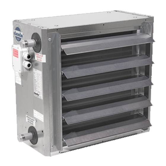
3. Description
1
1
1
2
3
4
I 097/09/02/0.5 GB
Wall- and ceiling-mounted units - The simple solution
incorrect
installation
and
1
M8 screw
2
Electrical junction box
3
Flow pipework
4
Return pipework
1
TIP 5000 Unit heaters
Installation instructions
Dimensions*
Model/Type
Height
54**36
500
55**36
600
56**36
700
57**36
800
* Dimensions without fan guard and air outlet louvre
4. Water pipe connections
The flow and return pipework should be connected to the unit
heater as indicated on the unit.
When connecting the flow and return pipework to
the unit heater, ensure that the threaded parts of
the heat exchanger are held rigid with pipe pliers or
similar to prevent them from becoming damaged or
bent.
5. Fixing
TIP 5000 unit heaters can be:
wall-mounted using wall brackets type 3*044
l
l
ceiling-mounted using universal 4-point brackets, type 30042
The unit can also be fixed using M8 ceiling rods or similar (by
others). When fixing a unit to the wall or ceiling, a minimum
gap A should be allowed between the fan guard and the wall
or ceiling. If this gap is not observed the performance of the unit
may be impaired and the noise level may increase.
Minimum gap between units and wall/ceiling
Model
Type
4
54*036
5
55*036
6
56*036
7
57*036
A
SYSTEMS FOR HEATING · COOLING · VENTILATING
1.57
Width
Depth
500
280
600
280
700
280
800
280
Minimum gap
A (mm)
160
180
230
300
Advertisement

Related Manuals for Kampmann TIP 5000


Summary of Contents for Kampmann TIP 5000
-
Page 1: Installation Instructions
57**36 damaged to other units or systems! * Dimensions without fan guard and air outlet louvre Kampmann unit heaters are intended only to be used to heat and ventilate industrial premises, assembly and production 4. Water pipe connections plants, retail premises, sports halls and greenhouses. The units... - Page 2 Wall- and ceiling-mounted units · The simple solution Wiring · Commissioning · Service and maintenance 6. Wiring TIP 5000 unit heaters come with a 2-stage, 3-phase 400 V motor with Y/ windings. The motor is protected by thermal cutouts in the windings of the motor which automatically switch off the motor via the stage switch if they detect overheating in the motor.
Need help?
Do you have a question about the TIP 5000 and is the answer not in the manual?
Questions and answers