
Subscribe to Our Youtube Channel
Related Manuals for Kampmann Katherm QK 190


Summary of Contents for Kampmann Katherm QK 190
- Page 1 Katherm QK ► Assembly, installation and operating instructions Keep these instructions in a safe place for future use! Issue11/22EN SAP No.1666194...
-
Page 3: Table Of Contents
Table of contents 1 General ..........................5 1.1 About these instructions ........................1.2 Explanation of Symbols.......................... 2 Safety............................ 6 2.1 Correct use............................. 2.2 Limits of operation and use........................2.3 Risk from electrocution!......................... 2.4 Personnel requirements - Qualifications ....................2.5 Personal Protective Equipment ......................3 Transport, storage and packaging.................. - Page 4 7.4.2 Connection (*C1)............................32 8 Pre-commissioning checks....................36 9 Operation..........................37 9.1 Operation of electromechanical control ....................37 9.2 Operation of the KaController........................ 37 9.2.1 Function keys, display elements ........................ 37 9.2.2 KaController type 3210001, type 3210002, type 3210006 ................ 40 10 Maintenance .........................
-
Page 5: General
Katherm QK Assembly, installation and operating instructions General About these instructions These instructions ensure the safe and efficient handling of this equipment. These instructions form an integral part of the equipment and have to be kept in the direct vicinity of the equipment and available to personnel at all times. All personnel must have carefully read through these instructions prior to commencing all work on the equipment. -
Page 6: Safety
Katherm QK Assembly, installation and operating instructions Safety This section provides an overview of all important safety aspects to ensure optimum protection of personnel as well as safe and trouble-free operation. In addition to the safety instructions in these operating instructions, the valid safety, accident pre- vention and environmental protection regulations must be observed for the area of use of the unit. - Page 7 Katherm QK Assembly, installation and operating instructions Limits of operation and use Limits of operation Min./max. water temperature °C 15-90 Min./max. air intake temperature °C 15-40 Min./max. air humidity 15-75 Min. operating pressure bar/kPa Max. operating pressure bar/kPa 10/1000 Min./max. glycol percentage 25-50 Tab. 1: Limits of operation Operating voltage...
-
Page 8: Risk From Electrocution
Katherm QK Assembly, installation and operating instructions IMPORTANT NOTE! Danger of frost in cooling mode! There is a risk of the heat exchanger freezing when used in unheated rooms. Make sure that the unit is equipped with a frost protection sensor and/or thermostat in this case. IMPORTANT NOTE! Warning of misuse! In the event of misuse, as itemised below, there is a danger of limited or failing operation of the unit. -
Page 9: Personnel Requirements - Qualifications
Katherm QK Assembly, installation and operating instructions Personnel requirements - Qualifications Expertise The installation of this product requires specialist knowledge of heating, cooling, ventilation, installation and electrical engin- eering. This knowledge, generally learned in professional training in one of the fields mentioned above, is not described sep- arately. -
Page 10: Transport, Storage And Packaging
IMPORTANT NOTE! Warranty claims can only be made within the applicable period for complaints. (More information is avail- able in the T&Cs on the Kampmann website) IMPORTANT NOTE! 2 people are needed to transport the unit. Wear personal protective clothing when transporting the unit. -
Page 11: Storage
Katherm QK Assembly, installation and operating instructions Storage Store packaging under the following conditions: Do not store outdoors. Store in a dry and dust-free place. Store in a frost-free place. Do not expose to aggressive media. Protect from direct sunlight. Avoid mechanical vibrations and shocks. -
Page 12: Technical Data
Katherm QK Assembly, installation and operating instructions Technical data Unit Katherm QK (performance values for roll-up grille) Size QK 190 QK 215 Trench width [mm] Trench height [mm] Trench length [mm] 1000 - 3200 1000 - 3200 Air volume flow [m³/h] 43 - 548 43 - 548 Heat output, 2-pipe... -
Page 13: Construction And Function
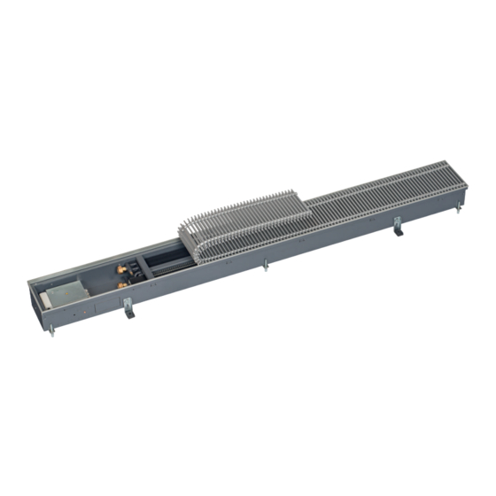
Katherm QK Assembly, installation and operating instructions Construction and function Overview Fig. 1: Katherm QK at a glance Easy to connect Frame edge (matches grille colour) Load-bearing height adjustment feet Connection-ready control box Eurokonus valve connection Height adjustment feet with sound insulation Floor trench Coil EC fan... -
Page 14: Installation And Wiring
Katherm QK Assembly, installation and operating instructions Installation and wiring Requirements governing the installation site Only install and assemble the unit if the following conditions are met: Make sure that the unit is securely suspended/standing. Ensure that the airflow can circulate freely. Provide adequate space for appropriately sized flow and return water connections on site (Connection to the pipe network [} 20]). -
Page 15: Installation Steps
Katherm QK Assembly, installation and operating instructions 6.2.1 Installation steps... - Page 16 Katherm QK Assembly, installation and operating instructions...
- Page 17 Katherm QK Assembly, installation and operating instructions...
- Page 18 Katherm QK Assembly, installation and operating instructions Separately packed roll-up grilles, for instance when using installation covers to protect the trenches from dirt, are rolled up in the factory. The grille can become slightly over-long due to the steel springs extending. Unrolling the grille and laying it flat for a few hours can return the grille to its original length.
-
Page 19: Screed Work
Katherm QK Assembly, installation and operating instructions 6.2.2 Screed work The following work needs to have been completed before screeding can begin: Water has been correctly connected. The electrical connections have been correctly wired. The unit is correctly positioned and levelled. There are no sound bridges to the concrete slab, especially in the area of the height adjustment feet. -
Page 20: Connection To The Pipe Network
Katherm QK Assembly, installation and operating instructions 6.3.1 Connection to the pipe network Katherm QK 190, trench height 112 mm Front view Side view (cross-section) Window side Room side Top view (without cover panel) Window side Room side Top view (without cover panel) - Page 21 Katherm QK Assembly, installation and operating instructions Katherm QK 215, trench height 112 mm Front view Side view (cross-section) Window side Room side Top view (without cover panel) Window side Room side Top view (without cover panel) Flow Return Valve body, ½” straight, type 346909, pre-settable Thermoelectric actuator 24 V, type 146906 ½”...
-
Page 22: Katherm Qk Supply Air Modules (Optional)
Connecting brackets Supply air slider Reinforcing struts Perforated plate Filter Example of Optiline roll-up grille Kampmann QK shown with Optiline roll-up grille Slider Trench width [mm] Trench length [mm] Trench height [mm] Supply air spigot [mm] Design air volume flow [m³/h]... - Page 23 Katherm QK Assembly, installation and operating instructions Supply air spigot (oval) 51 mm x 128 mm Primary air volume flow Slider position 30% open Slider position 50% open Slider position 75% open Slider position 100% open Sound power level 30dB(A) Adjusting the slider position The height of the supply air module is adjusted using the threaded rods and connected by the installation brackets to the sub- strate.
-
Page 24: Electrical Connection
Katherm QK Assembly, installation and operating instructions Electrical connection Maximum electrical rating values Katherm QK, 230 V electromechanical version (*00) Trench Nominal Mains fre- Nominal Nominal Leakage cur- Ri analogue IP class Protection length [mm] voltage [V quency [Hz] power [W] current [A] rent [mA] input [kΩ]... -
Page 25: Electromechanical Connection, 24 V (*24)
Katherm QK Assembly, installation and operating instructions Katherm QK, KaControl version (*C1) Trench Nominal Mains fre- Nominal Nominal Leakage cur- Ri analogue IP class Protection length [mm] voltage [V quency [Hz] power [W] current [A] rent [mA] input [kΩ] class 1000 0.08 IP00... -
Page 26: Verlegepläne Katherm Qk Elektromechanisch 24 V.pdf
Electrical cabling - BMS control Trench convector Katherm QK 24 V / 0-10 V DC Actuator Type 146906 W1: On-site fuse (0.63 A) Automation station including central power supply (24 V DC) * Lay shielded cables (e.g. IY(ST)Y, 0.8 mm), separately from high-voltage cables. W1: Voltage supply and control signal for (on-site fuse 0.63 A) and actuator. - Page 27 Electrical cabling – Control via clock thermostat, type 30456 Trench convector Katherm QK 24 V / 0-10 V DC Actuator Type 146906 Junction box by others Central voltage supply 24 V DC on site Clock thermostat Type 30456 * Lay shielded cables (e.g. IY(ST)Y, 0.8 mm) separately from power cables. W1: Voltage supply and control signal for fan (on-site fuse 0.63 A) and actuator.
-
Page 28: Electromechanical Connection, 230 V (*00)
Katherm QK Assembly, installation and operating instructions Electromechanical connection, 230 V (*00) Note these points in the following layout plans for Katherm QK with electromechanical control 230 V(*00): Comply with the details on cable types and cabling with due consideration of VDE 0100. Without *: NYM-J. -
Page 29: Verlegepläne Katherm Qk Elektromechanisch 230 V.pdf
Electrical cabling - BMS control Mains power 230 V AC Trench convector Katherm QK Fuse by others 24 V / 0-10 V DC Actuator Type 146906 Netz 230 VAC Bodenkanal Absicherung Katherm QK nano bauseits 230 V / 0-10 VDC Automation station * Lay shielded cables (e.g. - Page 30 Electrical cabling – Control via room thermostat, type 342924 * Lay shielded cables (e.g. IY(ST)Y, 0.8 mm) separately from power cables. W1: power supply W2: Control signal for fan and actuator W3: Operating mode changeover (optional) Subject to technical modifications: Refer to the control accessory documentation in the event of deviation from the circuit diagrams!
-
Page 31: Kacontrol (*C1)
Katherm QK Assembly, installation and operating instructions KaControl (*C1) 7.4.1 KaController installation Fig. 4: Installation of flush-mounted back box Electrical connection Connect the KaController to the nearest KaControl unit in line with the wiring diagram. The maximum bus length between the KaController and the KaControl master unit is 30 m. -
Page 32: Connection (*C1)
Katherm QK Assembly, installation and operating instructions 7.4.2 Connection (*C1) General information Route all low voltage cables along the shortest route. Ensure that low-voltage and power cables are separated, using metal partitions on cable harnesses. Wrong! Use only shielded cables as low-voltage and bus cables. Star-shaped wiring of the bus lines. - Page 33 Katherm QK Assembly, installation and operating instructions Observe these points in the following installation diagrams for Katherm QK with KaControl: Comply with the details on cable types and cabling with due consideration of VDE 0100. Without *: NYM-J. The requisite number of wires, including PE conductor, is stated on the cable. Cross-sections are not stated, as the cable length is involved in the calculation of the cross-section.
- Page 34 Katherm QK with KaController Single-circuit control, or maximum 30 Katherm QK units by CAN bus. Electrical cabling - 24 V Open / Close valve, external KaController Lay shielded cables (e.g. IY(ST)Y 0,8 mm) separately from high-voltage cables. Lay shielded, paired cables, e.g. UNITRONIC@ BUS LD 2x2x0,22 or equivalent, separately from high-voltage cables. W1: Power supply W2: Analogue input Al1 (optional connection), max.
- Page 35 KaControl electrical cabling - BMS control ** Lay shielded, paired cables, e.g. CAT5 (AWG23) of at least the same value, separately from high-voltage cables. W1: Power supply W2: Control signal for fan and actuator. Subject to technical modifications: Refer to the control accessory documentation in the event of deviation from the circuit diagrams!
-
Page 36: Pre-Commissioning Checks
Katherm QK Assembly, installation and operating instructions Pre-commissioning checks Before initial commissioning, check whether all the necessary conditions have been met so that the unit can function safely and properly. Structural tests Check that the unit is securely standing and fixed. Check the horizontal installation/suspension of the unit. -
Page 37: Operation
Katherm QK Assembly, installation and operating instructions Operation Operation of electromechanical control Room thermostat type 194000342924 Electronic room thermostat with continuously variable speed control, sup- plied as a surface-mounted wall-mounted unit on a flush-mounted box in visually discreet design With thermal feedback, room temperature setting and speed pre-setting us- ing dials Internal temperature sensor NTC Digital input for Day/Eco changeover... - Page 38 Katherm QK Assembly, installation and operating instructions Fig. 9: KaController with function keys, type 3210002 Display with LED background lighting ON/OFF key (depending on setting) ON/OFF Eco mode/Day mode (factory setting) TIMER button ESC button Set time back to standard view Set timer programs Navigator dial House symbol...
- Page 39 Katherm QK Assembly, installation and operating instructions Fig. 12: Display Display of setpoint room temperature Current time Timer program enabled Weekday Alarm Selected function is locked “External ventilation“ mode is locked Filter alert Eco mode Setpoint setting enabled Fan control setting Auto-0-1-2-3-4-5 Ventilation mode Cooling mode Heating mode...
-
Page 40: Kacontroller Type 3210001, Type 3210002, Type 3210006
Katherm QK Assembly, installation and operating instructions 9.2.2 KaController type 3210001, type 3210002, type 3210006 Press and hold down the navigator dial for 3 seconds to move from one menu to the next. Switching on the unit Option 1: Turn the navigator dial. Option 2: Press the ON/OFF button. -
Page 41: Maintenance
Katherm QK Assembly, installation and operating instructions Maintenance 10.1 Securing against reconnection DANGER! Risk of death by unauthorised or uncontrolled restart! Unauthorised or uncontrolled restarting of the equipment can result in serious injury or death. Before restarting, ensure that all safety devices are fitted and working properly and that there is no haz- ard to humans. -
Page 42: Maintenance Work
Katherm QK Assembly, installation and operating instructions 10.3 Maintenance work 10.3.1 Clean the inside of the unit Check all elements that come into contact with air (internal surfaces of the unit, outlet elements etc.) for dirt or deposits dur- ing maintenance and use a commercially available product to remove. -
Page 43: Faults
Katherm QK Assembly, installation and operating instructions Faults The following chapter describes possible causes of faults and the work needed to rectify them. Should faults occur frequently, shorten the maintenance intervals in line with the actual loading on the unit. Contact the manufacturer with any faults that cannot be rectified using the following information. -
Page 44: Kacontrol Faults
Katherm QK Assembly, installation and operating instructions 11.2 KaControl faults Code Alarms Priority Faulty control sensor. Motor fault. Room frost protection. Condensation alarm. General alarm. Sensor AI1, AI2 or AI3 faulty. Unit frost protection. EEPROM error. Offline slave in the CAN bus network. Tab. 10: KaControl unit alarms Code Alarms... -
Page 45: List Of Kacontrol Parameters
Katherm QK Assembly, installation and operating instructions List of KaControl parameters 12.1 KaController parameter list Para- Function Standard Min. Max. Unit Comment meter Address in Mod- t001 Serial address bus network Baud rate 0 = Baud rate 4800 t002 1 = Baud rate 9600 2 = Baud rate 19200 Background lighting function 0 = Slow fade in, fast fade out... -
Page 46: Certificates
Katherm QK Assembly, installation and operating instructions Certificates... -
Page 47: 142_Eu_Konformitätserklärung_Katherm_Qk_Hk_Qk_Nano.pdf
EU-Konformitätserklärung EU Declaration of Conformity Déclaration de Conformité CE Deklaracja zgodności CE EU prohlášení o konformite KAMPMANN Wir (Name des Anbieters, Anschrift): GMBH & Co. KG Friedrich-Ebert-Str. 128-130 We (Supplier’s Name, Address): 49811 Lingen (Ems) Nous (Nom du Fournisseur, Adresse): My (Nazwa Dostawcy, adres): My (Jméno dodavatele, adresa):... - Page 48 Conformément aux dispositions de Directive: Zgodnie z postanowieniami Dyrektywy: Odpovídající ustanovení směrnic: 2014/30/EU EMV-Richtlinie 2014/35/EU Niederspannungsrichtlinie Hendrik Kampmann Lingen (Ems), den 01.09.2020 ___________________________________ Ort und Datum der Ausstellung Name und Unterschrift des Befugten Place and Date of Issue Name and Signature of authorized person Lieu et date d’établissement...
- Page 49 Katherm QK Assembly, installation and operating instructions Table Tab. 1 Limits of operation ..............................7 Tab. 2 Operating voltage ..............................7 Tab. 3 Water quality................................7 Tab. 4 Technical data – Katherm QK supply air module....................22 Tab. 5 Maximum electrical rating values ......................... 24 Tab.
- Page 52 Country Contact Kampmann UK Ltd. Dial House, Govett Avenue Shepperton, Middlesex, TW17 8AG T +44 1932/ 228592 Great Britain F +44 1932/ 228949 E info@kampmann.co.uk W Kampmann.co.uk...
Need help?
Do you have a question about the Katherm QK 190 and is the answer not in the manual?
Questions and answers