
Subscribe to Our Youtube Channel
Related Manuals for Kampmann UniLine 10


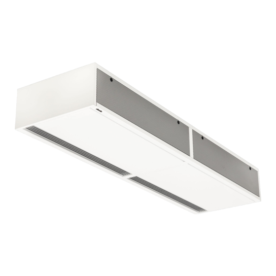
Summary of Contents for Kampmann UniLine 10
- Page 1 UniLine Assembly and Installation Instructions Keep these instructions in a safe place for future use! Kampmann.de/installation_manuals I258 11/20 EN SAP-Nr. 1021205...
- Page 2 Kampmann GmbH & Co. KG Kampmann UK Ltd. Friedrich-Ebert-Str. 128 - 130 Dial House, Govett Avenue 49811 Lingen (Ems) Shepperton, Middlesex, TW17 8AG Germany Great Britain +49 591 7108-660 +44 (0)1932 228592 +49 591 7108-173 +44 (0)1932 228949 export@kampmann.de info@kampmann.co.uk...
-
Page 3: Table Of Contents
Kampmann assembly and installation instructions – UniLine door air curtains Contents About these instructions Key to symbols Intended use Safety information Transport and storage Scope of delivery Installation 5.1 Installation of UniLine model 10 - 25 with wall brackets 5.2 Installation of UniLine model 30 with wall brackets 5.3 Installation of UniLine model 10 - 25 with ceiling brackets... - Page 4 Allgemeines | Informationen zu dieser Anleitung Kampmann assembly and installation instructions – UniLine door air curtains 10.5.2.1 Function keys, display elements 10.5.2.2 Operation 10.6 Alarm messages 10.7 Troubleshooting A11 – A17 10.8 Cabling 10.8.1 General information 10.8.2 KaController 10.8.3 External room temperature sensor 10.8.4 Inputs for processing external contacts (e.g.
-
Page 5: About These Instructions
General | About these instructions, key to symbols Kampmann assembly and installation instructions – UniLine door air curtains About these instructions Carefully read these instructions in full prior to any assembly and installation work! Anyone involved with the installation, commissioning and use of this... -
Page 6: Intended Use
Kampmann assembly and installation instructions – UniLine door air curtains Intended use Kampmann UniLine door air curtains are produced in compliance with the state of the art and recognised safety regulations. Nevertheless their use can result in danger to people or damage to the unit or other material property if they are not properly installed or properly used. - Page 7 Kampmann assembly and installation instructions – UniLine door air curtains Limits of operation and use Limits of operation and use Limits of operation Min./max. water temperature °C 40 - 90 Min./max. air intake temperature °C 6 - 40 Min./max. air humidity 15 - 75 Max.
-
Page 8: Safety Information
Safety information | Hazards, responsibility Kampmann assembly and installation instructions – UniLine door air curtains Safety information Only allow a qualified electrician to perform installation, assembly and maintenance work on electrical units in compliance with VDE guidelines. Wiring should comply with the applicable VDE regulations and provisions laid down by the regional electricity providers. -
Page 9: Transport And Storage
Kampmann assembly and installation instructions – UniLine door air curtains Transport and storage, delivery, installation Transport and storage Please note all applicable safety and accident prevention regulations. Caution! Risk of sharp edges! Wear gloves, safety shoes and suitable protective clothing during transportation! Two people are needed to carry the unit. -
Page 10: Installation Of Uniline Model 10 - 25 With Wall Brackets
Installation | UniLine model 10 - 25 with wall brackets Kampmann assembly and installation instructions – UniLine door air curtains 5.1. Installation UniLine model 10 - 25 with wall brackets Front view Cross-section Plan view Wall bracket, plan view Conn. 3/4”... -
Page 11: Installation Of Uniline Model 30 With Wall Brackets
Kampmann assembly and installation instructions – UniLine door air curtains Installation | UniLine model 30 with wall brackets 5.2. Installation UniLine model 30 with wall brackets Front view Cross-section Plan view Wall bracket, plan view Conn. 3/4” General view Fixing points for brackets Outlet air rectifier Perforated panel with filter –... -
Page 12: Installation Of Uniline Model 10 - 25 With Ceiling Brackets
Installation | UniLine model 10 - 25 with ceiling brackets Kampmann assembly and installation instructions – UniLine door air curtains 5.3. Installation UniLine model 10 - 25 with ceiling brackets Front view Cross-section Plan view Ceiling bracket, plan view Conn. 3/4”... -
Page 13: Installation Of Uniline Model 30 With Ceiling Brackets
Kampmann assembly and installation instructions – UniLine door air curtains Installation | UniLine model 30 with ceiling brackets 5.4. Installation UniLine model 30 with ceiling brackets Front view Cross-section Plan view Ceiling bracket, plan view Conn. 3/4” General view Fixing points for brackets Outlet air rectifier Perforated panel with filter –... -
Page 14: Hydraulic Connections
Hydraulic connection | UniLine door air curtains Kampmann assembly and installation instructions – UniLine door air curtains Hydraulic connections Safety information Connecting up the hydraulics requires expertise in heating engineering. Note the following guidelines for integrating the system before starting work on the unit or on the control: Maximum temperature of heating medium 90°C. -
Page 15: Installation Of Thermoelectric Shut-Off Valve And Outlet Temperature Limit Valve
Kampmann assembly and installation instructions – UniLine door air curtains Hydraulic connection | UniLine door air curtains 6.1 Installation of thermoelectric shut-off valve and outlet temperature limit valve Flow Return Outlet temperature limit valve, type 100967; Installation in the flow... -
Page 16: Installation Of Remote Sensor For Outlet Air Temperature Limit Valve
Hydraulic connection | UniLine door air curtains Kampmann assembly and installation instructions – UniLine door air curtains 6.2 Installation of remote sensor for outlet air temperature limit valve Remote sensor for outlet temperature limit valve (accessory), fitting the pipe clips... -
Page 17: Technical Data
Kampmann assembly and installation instructions – UniLine door air curtains Technical data | Models Technical data Unit UniLine AC Model Length 1000 1500 2000 2500 3000 Weight Current consumption 1.82 2.67 3.70 4.75 7.81 Max. electrical power consumption 1604 Mains voltage... -
Page 18: Commissioning
Commissioning | Checks, switching-on, permanent decommissioning Kampmann assembly and installation instructions – UniLine door air curtains Commissioning Pre-commissioning checks Is the unit fitted to the wall/ceiling with the appropriate fixing brackets? Electrical connection: Is all cabling in accordance with the ambient conditions and... -
Page 19: Maintenance
Kampmann assembly and installation instructions – UniLine door air curtains Maintenance | Filters, fans and heat exchanger Maintenance Filters The heat output of the unit will be reduced with dirty filters and the fans can be damaged by overloading. Regularly check the intake filters. -
Page 20: Electrical Wiring
Electrical wiring | Safety information, electrical wiring Kampmann assembly and installation instructions – UniLine door air curtains Electrical wiring Safety information The wiring of this product requires expert knowledge of electrical engineering. This knowledge, generally learned in vocational training in one of the fields stated, is not described separately here. -
Page 21: Uniline Ac, Electromechanical Model (*00)
The required speed (= voltage level) is switched on the fans via the foot contact of the switch. The heating valve (if fitted) is opened or closed by a separate 230 V contact. Insert a jumper on the stage switch as per the table when using Kampmann stage switches! Control option Type... - Page 22 Electrical wiring | UniLine AC, electromechanical model (*00) Kampmann assembly and installation instructions – UniLine door air curtains UniLine AC electrical installation Operation of single UniLine AC door air curtain Example: 5-stage summer-winter switch surface-mounted, type 100928 UniLine AC Mains power...
-
Page 23: Uniline Ac, Model For On-Site Control (*P)
Kampmann assembly and installation instructions – UniLine door air curtains Electrical wiring | UniLine AC, model for on-site control (*P) 10.2 UniLine AC, model for on-site control (*P) Wiring description: The mains voltage is wired to the voltage supply terminals on the door air curtain. - Page 24 Electrical wiring | UniLine AC, model for on-site control (*P) Kampmann assembly and installation instructions – UniLine door air curtains...
-
Page 25: Uniline Ec, Electromechanical Model With Internal Fault Signal Processing (*00)
Kampmann assembly and installation instructions – UniLine door air curtains Electrical wiring | UniLine EC, electromechanical model with internal fault signal processing (*00) 10.3 UniLine EC, electromechanical model with internal fault signal processing (*00) Wiring description: The mains voltage is wired to the voltage supply terminals on the door air curtain. - Page 26 Electrical wiring | UniLine EC, electromechanical model with internal fault signal processing (*00) Kampmann assembly and installation instructions – UniLine door air curtains...
- Page 27 Kampmann assembly and installation instructions – UniLine door air curtains Electrical wiring | UniLine EC, electromechanical model with internal fault signal processing (*00)
-
Page 28: Uniline Ec, Electromechanical Model With External Fault Signal Processing (*T)
Electrical wiring | UniLine EC, electromechanical model with external fault signal processing (*T) Kampmann assembly and installation instructions – UniLine door air curtains 10.4 UniLine EC, electromechanical model with external fault signal processing (*T) Feed line Control signal Wiring description:... - Page 29 Kampmann assembly and installation instructions – UniLine door air curtains Electrical wiring | UniLine EC, electromechanical model with external fault signal processing (*T)
- Page 30 Electrical wiring | UniLine EC, electromechanical model with external fault signal processing (*T) Kampmann assembly and installation instructions – UniLine door air curtains...
-
Page 31: Uniline Ec, Kacontrol (*C1) Option
10.5 UniLine EC, KaControl version (*C1) 10.5.1 Intended use Kampmann KaControllers and KaControl modules are built in line with the state of the art and recognised safety regulations. Nevertheless, their use can result in danger to people or damage to the units or other material property if they are not appropriately installed and operated or correctly and properly used. -
Page 32: Operation Of The Kacontroller
Kampmann assembly and installation instructions – UniLine door air curtains 10.5.2 Operation of the KaController The KaController is capable of controlling the wide range of Kampmann systems. KaControllers are equipped with state of the art technology and offer users the option of adapting the air conditioning of buildings to individual needs. -
Page 33: Function Keys, Display Elements
Kampmann assembly and installation instructions – UniLine door air curtains Electrical wiring | UniLine EC, KaControl model (*C1) 10.5.2.1 Function keys, display elements Display with LED background lighting ON/OFF button (depending on setting) – ON / OFF (factory setting) – Eco mode/Day mode TIMER button –... -
Page 34: Operation
Electrical wiring | UniLine EC, KaControl model (*C1) Kampmann assembly and installation instructions – UniLine door air curtains 10.5.2.2 Operation The KaController is operated by the navigator and the function keys. The functions that can be called up and set using the navigator are identical on both versions (with and without function keys on the side). - Page 35 Kampmann assembly and installation instructions – UniLine door air curtains Electrical wiring | UniLine EC, KaControl model (*C1) Switching control off and on When the control is switched on, the display shows the default view with the current room temperature setpoint and the fan stage set.
- Page 36 Electrical wiring | UniLine EC, KaControl model (*C1) Kampmann assembly and installation instructions – UniLine door air curtains Fan setting Press the FAN key (quick access) or use the navigator dial to call up the “Fan setting” selection menu. Calling up the “Fan setting” menu using the navigator dial:...
- Page 37 Kampmann assembly and installation instructions – UniLine door air curtains Electrical wiring | UniLine EC, KaControl model (*C1) Summer mode/winter mode adjustment Press the MODE key (quick access) or use the navigator dial to call up the “Operating modes” selection menu.
- Page 38 Electrical wiring | UniLine EC, KaControl model (*C1) Kampmann assembly and installation instructions – UniLine door air curtains Time setting Press the TIMER key (quick access) or use the navigator dial to call up the “Time setting” selection menu. Calling up the “Time setting” menu using the navigator dial:...
- Page 39 Kampmann assembly and installation instructions – UniLine door air curtains Electrical wiring | UniLine EC, KaControl model (*C1) Time switch programs The KaController provides the option of programming switching on and off times using a timer program if rooms are only to be air conditioned during certain times of the day.
- Page 40 Electrical wiring | UniLine EC, KaControl model (*C1) Kampmann assembly and installation instructions – UniLine door air curtains Press the TIMER key 2x (quick access) or use the navigator dial to call up the “Timer programs” selection menu. Use the navigator dial to call up the “Timer programs” menu.
- Page 41 Kampmann assembly and installation instructions – UniLine door air curtains Electrical wiring | UniLine EC, KaControl model (*C1) Step 4: Set the switch-off time you require by turning the navigator dial. Once the minutes have been set, press the navigator dial ( Step 1) to apply the switch-off time and to call up the timer start screen.
- Page 42 Electrical wiring | UniLine EC, KaControl model (*C1) Kampmann assembly and installation instructions – UniLine door air curtains Deleting all timer programs and time Perform the following steps to delete all timer programs and the time: 1. Switch off the KaController by:...
-
Page 43: Alarm Messages
Kampmann assembly and installation instructions – UniLine door air curtains Electrical wiring | UniLine EC, KaControl model (*C1) 10.6 Alarm messages The KaController displays faults by means of the alarm messages listed in the table below. The alarm messages are displayed according to their priority. - Page 44 Electrical wiring | UniLine EC, KaControl model (*C1) Kampmann assembly and installation instructions – UniLine door air curtains 10.7 KaController installation Installation/Dismantling Electrical wiring Connect the KaController to the nearest KaControl in accordance with the wiring diagram. The maximum bus length between the KaController and the KaControl is 30 m.
-
Page 45: Troubleshooting
Kampmann assembly and installation instructions – UniLine door air curtains Electrical wiring | UniLine EC, KaControl model (*C1) 10.7.1 Troubleshooting A11 – A17 The fault messages of a slave unit are not displayed on the KaController. Only the fault messages of the master unit are displayed on the KaController. - Page 46 Electrical wiring | UniLine EC, KaControl model (*C1) Kampmann assembly and installation instructions – UniLine door air curtains A14 Condensation alarm The condensation alarm of a unit with KaControl is displayed on the KaController by the display “A14”. The unit with an active condensation alarm automatically closes all valves.
-
Page 47: Cabling
Kampmann assembly and installation instructions – UniLine door air curtains Electrical wiring | UniLine EC, KaControl model (*C1) 10.8 Cabling 10.8.1 General information Lay all low-voltage cables along the shortest route. Ensure that low-voltage and high-voltage cables are separated, using metal partitions in cable ducts. -
Page 48: External Room Temperature Sensor
Electrical wiring | UniLine EC, KaControl model (*C1) Kampmann assembly and installation instructions – UniLine door air curtains 10.8.3 External room temperature sensor ** Lay shielded, paired All KaControl master units have an analogue input to connect an cables, e.g. CAT5 external room temperature sensor. -
Page 49: Addressing - Single-Circuit Controls
Kampmann assembly and installation instructions – UniLine door air curtains Electrical wiring | UniLine EC, KaControl model (*C1) 10.9 Addressing – Single-circuit controls Door air curtains in single-circuit controls with a maximum of 6 units need not be addressed. Define the master unit/slave unit by connecting the KaController. -
Page 50: Adjusting Unit Configuration By Dip Switch
Electrical wiring | UniLine EC, KaControl model (*C1) Kampmann assembly and installation instructions – UniLine door air curtains 10.10 Setting the unit configuration by means of DIP switches Set the configuration of a KaControl unit using the DIP switch on the PCB. - Page 51 Kampmann assembly and installation instructions – UniLine door air curtains Electrical wiring | UniLine EC, KaControl model (*C1) DIP switch no. 1 DIP switch no. 1 must be set to ON to actuate a KaControl by means of 0…10 V signals within a building management system provided by others.
-
Page 52: Parameter Settings
Electrical wiring | UniLine EC, KaControl model (*C1) Kampmann assembly and installation instructions – UniLine door air curtains 10.11 Parameter settings Special system requirements can be configured using parameter settings in the Service menu. Special system requirements may include: Display: room temperature or setpoint temperature Lock operating functions Set the absolute setpoint temperature or ±... -
Page 53: Parameter Settings
Kampmann assembly and installation instructions – UniLine door air curtains Electrical wiring | UniLine EC, KaControl model (*C1) 10.12. Parameter settings 10.12.1 Set absolute setpoint temperature or ± 3K Parameter P36 It may be necessary in office or hotel applications for the system operator to specify a base setpoint. -
Page 54: On/Off, Eco/Day Functions
Electrical wiring | UniLine EC, KaControl model (*C1) Kampmann assembly and installation instructions – UniLine door air curtains 10.12.2 ON/OFF, Eco/Day functions Parameter P38 The ON/OFF key function and the timer programs are specified using parameter P38. Use the ON/OFF button and the timer programs to switch the unit ON and OFF or between Eco and Day mode. - Page 55 Kampmann assembly and installation instructions – UniLine door air curtains Electrical wiring | UniLine EC, KaControl model (*C1) 10.12.3 DI2 function The digital input DI1 is predominantly used to execute specific functions. If the use of the digital input DI2 is needed, then the following settings have to be entered: 1.
-
Page 56: Function Of Digital Outputs V1 And V2
Electrical wiring | UniLine EC, KaControl model (*C1) Kampmann assembly and installation instructions – UniLine door air curtains 10.12.4 Function of digital outputs V1 and V2 The function of the digital output v1 is permanently assigned. The function of the digital output V2 can be configured using parameters. -
Page 57: Function Of Multifunctional Inputs Ai1, Ai2 And Ai3
Kampmann assembly and installation instructions – UniLine door air curtains Electrical wiring | UniLine EC, KaControl model (*C1) 10.12.5 Function of multifunctional inputs AI1, AI2 and AI3 The function of the multifunctional inputs AI1, AI2 and AI3 can be configured using parameter settings. - Page 58 Electrical wiring | UniLine EC, KaControl model (*C1) Kampmann assembly and installation instructions – UniLine door air curtains Function AI2 – Parameter P16 Parameter PI6 is used to set the function of the multifunctional input AI2. The multifunctional input AI2 can only be set using parameter P16 if DIP switch no.
-
Page 59: Functional Test Of The Connected Assemblies
Kampmann assembly and installation instructions – UniLine door air curtains Electrical wiring | UniLine EC, KaControl model (*C1) 10.13 Functional testing of connected assemblies The KaController provides the option of checking the function of the external units connected independently of the software application. The function of individual assemblies, such as the EC fan, can be directly activated and checked by means of inputs on the KaController. -
Page 60: Parameter List For Control Pcb
Electrical wiring | UniLine EC, KaControl model (*C1) Kampmann assembly and installation instructions – UniLine door air curtains 10.14 Parameter list for control PCB Function Standard Min. Max. Unit Comment P000 Software version P001 °C Base setpoint for setpoint entry ± 3K... - Page 61 Kampmann assembly and installation instructions – UniLine door air curtains Electrical wiring | UniLine EC, KaControl model (*C1) Function Standard Min. Max. Unit Comment P044 Function of digital input DI2 P045 kOhm Threshold voltage for potentiometer, which switches on unit...
- Page 62 Electrical wiring | UniLine EC, KaControl model (*C1) Kampmann assembly and installation instructions – UniLine door air curtains Function Standard Min. Max. Unit Comment P086 Dependence of idronic algorithms Slave 6 P087 Dependence of idronic algorithms Slave 7 P088 Dependence of idronic algorithms Slave 8...
-
Page 63: Kacontroller Parameters
Kampmann assembly and installation instructions – UniLine door air curtains Electrical wiring | UniLine EC, KaControl model (*C1) 10.15 KaController parameters 10.15.1 General Specific user requirements can be activated and disabled by means of parameter settings in the KaController, for instance the minimum and maximum setpoint temperature can be set using parameters in the KaController. -
Page 64: Kacontroller Parameter List
Electrical wiring | UniLine EC, KaControl model (*C1) Kampmann assembly and installation instructions – UniLine door air curtains 10.15 KaController parameter list Function Standard Einheit Comment t001 Serial address t002 Baud rate 0 = Baud rate 4800 1 = Baud rate 9600... - Page 65 Kampmann assembly and installation instructions – UniLine door air curtains Electrical wiring | UniLine EC, KaControl model (*C1)
- Page 66 Electrical wiring | UniLine EC, KaControl model (*C1) Kampmann assembly and installation instructions – UniLine door air curtains...
- Page 68 Kampmann GmbH & Co. KG Kampmann UK Ltd. Friedrich-Ebert-Str. 128 - 130 Dial House, Govett Avenue 49811 Lingen (Ems) Shepperton, Middlesex, TW17 8AG Germany Great Britain +49 591 7108-660 +44 (0)1932 228592 +49 591 7108-173 +44 (0)1932 228949 export@kampmann.de info@kampmann.co.uk...
Need help?
Do you have a question about the UniLine 10 and is the answer not in the manual?
Questions and answers