
Related Manuals for Kampmann Wall HK


Summary of Contents for Kampmann Wall HK
- Page 1 Wall HK ► Assembly, installation and operating instructions Keep these instructions in a safe place for future use! Issue04/21EN SAP No.1428258...
-
Page 3: Table Of Contents
Table of contents 1 General ..........................5 1.1 About these instructions ......................... 1.2 Explanation of Symbols........................... 2 Safety............................ 6 2.1 Correct use.............................. 2.2 Limits of operation and use ........................2.3 Risk from electrocution!.......................... 2.4 Personnel requirements - Qualifications ....................2.5 Personal Protective Equipment ....................... 3 Transport, storage and packaging.................. - Page 4 7.2.1 Connection (*24)............................35 7.2.2 Cabling, Wall HK (*24), control by DDC/BMS.................... 36 8 Pre-commissioning checks ....................37 9 Maintenance ......................... 39 9.1 Securing against reconnection ........................ 39 9.2 Maintenance Schedule:........................... 39 9.3 Maintenance work..........................40 9.3.1 Replacing the filter............................ 40 9.3.2...
-
Page 5: General
Wall HK Assembly, installation and operating instructions General About these instructions These instructions ensure the safe and efficient handling of this equipment. These instructions form an integral part of the equipment and have to be kept in the direct vicinity of the equipment and available to personnel at all times. -
Page 6: Safety
Wall HK Assembly, installation and operating instructions Safety This section provides an overview of all important safety aspects to ensure optimum protection of personnel as well as safe and trouble-free operation. In addition to the safety instructions in these operating instructions, the valid safety, accident pre- vention and environmental protection regulations must be observed for the area of use of the unit. - Page 7 Wall HK Assembly, installation and operating instructions Limits of operation and use Limits of operation Min./max. water temperature °C/°F 40-90 / 104-194 Min./max. air intake temperature °C/°F 6-40 / 43-104 Min./max. air humidity 15-75 Min. operating pressure bar/kPa Max. operating pressure...
-
Page 8: Risk From Electrocution
Wall HK Assembly, installation and operating instructions IMPORTANT NOTE! Danger of frost in cooling mode! There is a risk of the heat exchanger freezing when used in unheated rooms. Make sure that the unit is equipped with a frost protection sensor and/or thermostat in this case. -
Page 9: Personnel Requirements - Qualifications
Wall HK Assembly, installation and operating instructions Personnel requirements - Qualifications Specialist knowledge The installation of this product requires specialist knowledge of heating, cooling, ventilation, installation and electrical engin- eering. This knowledge, generally learned in vocational training in one of the fields mentioned above, is not described separ- ately. -
Page 10: Transport, Storage And Packaging
IMPORTANT NOTE! Warranty claims can only be made within the applicable period for complaints. (More information is avail- able in the T&Cs on the Kampmann website) IMPORTANT NOTE! 2 people are needed to transport the unit. Wear personal protective clothing when transporting the unit. -
Page 11: Storage
Wall HK Assembly, installation and operating instructions Storage Store packaging under the following conditions: Do not store outdoors. Store in a dry and dust-free place. Store in a frost-free place. Do not expose to aggressive media. Protect from direct sunlight. -
Page 12: Technical Data
Wall HK Assembly, installation and operating instructions Technical data Unit Wall HK Model Width of basic unit [mm] 1100 1600 1900 Casing width [mm] 1250 1750 2050 Weight of basic unit [kg] Max. weight including cas- 22.50 29.00 43.50 51.70 ing [kg] Air volume [m³/h]... -
Page 13: Construction And Function
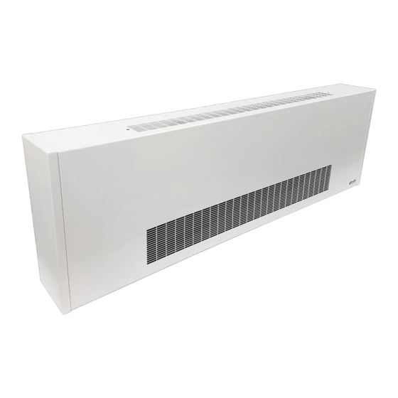
Brief description Wall HK are decentralised units for heating, cooling and filtering air, for use in hotels, offices and business premises, among others. Secondary air is drawn in filtered by the fan and passed through the copper/aluminium heat exchanger. Here the air is either heated or cooling depending on the temperature of the water in the heat exchanger. -
Page 14: Installation And Wiring
Wall HK Assembly, installation and operating instructions Installation and wiring Definition of the connection side Example of 2-pipe, connection on left Example of 2-pipe, connection on right Cooling Heating Example of 4-pipe, opposite end connections... -
Page 15: Requirements Governing The Installation Site
Wall HK Assembly, installation and operating instructions Requirements governing the installation site Only install and assemble the unit if the following conditions are met: Make sure that the unit is securely suspended/standing. Ensure that the airflow can circulate freely. Provide adequate space for appropriately sized flow and return water connections on site (Connection to the pipe network [} 28]). -
Page 16: Minimum Clearances
There needs to be a 50 mm freely accessible clearance above the casing to remove the casing. Example of basic unit, wall-hanging (without casing) Example of basic unit, wall-hanging (with casing) Fig. 2: Minimum clearances, Wall HK (mm) - Page 17 There needs to be a 50 mm freely accessible clearance above the casing to remove the casing. Example of basic unit, wall-hanging (without casing) Example of basic unit, wall-hanging (with casing) Fig. 3: Minimum clearances Wall HK (inch)
-
Page 18: Installation
Wall HK Assembly, installation and operating instructions Installation 2 people are needed to install the unit. CAUTION! Risk of injury from sharp metal housing! The inner metal of the casing can have sharp edges. Wear suitable protective gloves. IMPORTANT NOTE! Horizontal installation of units! When installing the units, ensure that they are completely horizontal to ensure proper operation. - Page 19 Wall HK Assembly, installation and operating instructions 6.4.1 Installation of basic unit Side view 124* 124* 0 8,5 Front view 0 21 Keyhole detail Top view Fig. 4: 321 Dimensions of basic unit and mounting points* [mm] A [mm] B [mm]...
- Page 20 Wall HK Assembly, installation and operating instructions Side view 4.9* 4.9* 0 0.3 Front view 0 0.8 Keyhole detail Top view Fig. 5: Dimensions of basic unit and mounting points* [inch] A [inch] B [inch] C [inch] D [inch] 32.1 20.9 22.3...
-
Page 21: Installation Of Casing
Wall HK Assembly, installation and operating instructions 6.4.2 Installation of casing Wall-hanging casing Front view Top view Isometric view In-wall casing Isometric view Front view Fig. 6: Dimensions of casing [mm] Model A [mm] 1250 1750 2050 Tab. 6: Dimensions of casing [mm]... - Page 22 Wall HK Assembly, installation and operating instructions Wall-hanging casing Front view Top view Isometric view In-wall casing Isometric view Front view Fig. 7: Dimensions of casing [inch] Model A [mm] 49.2 68.9 80.7 Tab. 7: Dimensions of casing [inch]...
- Page 23 Wall HK Assembly, installation and operating instructions General information on casings Casings are factory-fitted as standard. Always remove the casing ahead of maintenance work or when modifying the air outlet direction. Dismantle the casing (wall-mounted). Unscrew the screws on the left and right side of the air outlet.
- Page 24 Wall HK Assembly, installation and operating instructions Dismantle the casing (recessed in the wall). Loosen 2 screws (left and right) in the underside of the casing and unscrew from the retaining rail. Remove the casing (recessed in the wall). Push the casing upwards where it was previously screwed in place to loosen it from its fixing.
-
Page 25: Alteration Of The Air Outlet Direction
Wall HK Assembly, installation and operating instructions 6.4.3 Alteration of the air outlet direction If the unit is supplied without casing, the air outlet direction can be changed by altering the discharge adjustment plate: A) Front air discharge direction B) Top air discharge direction Fig. 8: A) Front air discharge direction... - Page 26 Wall HK Assembly, installation and operating instructions Loosen the flat-headed screws on the left and right to al- ter the discharge adjustment plate (the example shows alteration from front air outlet to top air outlet). Loosen the middle metal screw(s).
-
Page 27: Installation
Wall HK Assembly, installation and operating instructions Installation Hydraulic connection Note the following points when connecting the hydraulic side: Install and test safety components (expansion vessels, pressure relief valves and overflow valves). Route condensation lines with a sufficient cross-section without bends and narrow sections with a gradient to the in situ waste water pipe. -
Page 28: Connection To The Pipe Network
Wall HK Assembly, installation and operating instructions 6.5.1 Connection to the pipe network The flow and return connections are located as standard on the left side of the unit, seen from the front panel. The connec- tions on the 4-pipe unit are opposite end. - Page 29 Wall HK Assembly, installation and operating instructions Side view (heating or cooling) 2- Side view (heating or cooling) Side view from right (heating) 4- Side view from left (cooling) pipe, connection on left 2-pipe, connection on right pipe, opposite-end connections 4-pipe, opposite-end connections Fig. 12: Dimensions of water connection [mm]...
- Page 30 Wall HK Assembly, installation and operating instructions Provide a service hatch. Provide the following service hatch dimensions for maintenance and inspection of basic unit with casing by others. Fig. 14: Dimensions of service hatch [mm] Model Ceiling opening dimension A±15 [mm]...
-
Page 31: Insulating The Pipework
Wall HK Assembly, installation and operating instructions 6.5.2 Insulating the pipework Slide impermeable insulation (by others) along the pipe through the wall opening as far as the straight valve so that the insulation only ends above the condensate tray. -
Page 32: Connection, On-Site Pipework
Top view Fig. 16: Space for water connection pipework [mm] Drilling template, Wall HK: Suspension points and positions of pipe connection opening through the wall [mm] Front view Front view Front view 2-pipe, connection on left... - Page 33 Top view Fig. 17: Space for water connection pipework [inch] Drilling template, Wall HK: Suspension points and positions of pipe connection opening through the wall [inch] Front view Front view Front view 2-pipe, connection on left...
-
Page 34: Condensation Connection
Wall HK Assembly, installation and operating instructions 6.5.4 Condensation connection 6.5.4.1 Condensation drain with natural gradient It is essential that a condensation drain is connected and appropriate fixed to a condensation drain connector (drain size 15 mm/ 0.6 inch). Ensure that the gradient is at least 1 cm/m (0.1 inch/foot), without restrictions and without rising sec-tions of pipe to ensure the drainage of condensation from the basic unit. -
Page 35: Electrical Connection
Fig. 19: Terminal strip VK: Cooling valve Observe these points in the following wiring diagrams for the Wall HK with electromechanical control: Comply with the details on cable types and cabling with due consideration of NEC and CEC. Without *: NYM-J. The requisite number of wires, including protective earth, is stated on the cable. Cross-sections are not stated, as the cable length is involved in the calculation of the cross-section. -
Page 36: Cabling, Wall Hk (*24), Control By Ddc/Bms
Wall HK Assembly, installation and operating instructions 7.2.2 Cabling, Wall HK (*24), control by DDC/BMS... -
Page 37: Pre-Commissioning Checks
Wall HK Assembly, installation and operating instructions Pre-commissioning checks Check before initial commissioning whether all necessary conditions have been met so that the unit can function safely and properly. Structural tests Remove air outlet protection from the outlet air area. - Page 38 Wall HK Assembly, installation and operating instructions Condensation water connection Check whether the cooling valve switches off in the event of an alarm signal. Check whether the unit is connected leak-free to the on-site condensation connection. Check whether the waste water lines are clean and have a sufficient gradient.
-
Page 39: Maintenance
Wall HK Assembly, installation and operating instructions Maintenance Securing against reconnection DANGER! Risk of death by unauthorised or uncontrolled restart! Unauthorised or uncontrolled restarting of the equipment can result in serious injury or death. Before restarting, ensure that all safety devices are fitted and working properly and that there is no haz- ard to humans. -
Page 40: Maintenance Work
Wall HK Assembly, installation and operating instructions Maintenance work 9.3.1 Replacing the filter. CAUTION! Risk of injury from sharp metal housing! The inner metal of the casing can have sharp edges. Wear suitable protective gloves. Pull the filter from the Velcro strip, remove any dirt or change the filter if necessary. -
Page 41: Cleaning The Condensate Tray
Wall HK Assembly, installation and operating instructions 9.3.3 Cleaning the condensate tray Use a Phillips screwdriver to unscrew the 4 fixing screws. Remove the condensate tray from the basic unit. Clean the condensate tray. 9.3.4 Clean the inside of the unit Check all elements that come into contact with air (internal surfaces of the unit, outlet elements etc.) for dirt or deposits dur-... -
Page 42: Faults
Wall HK Assembly, installation and operating instructions Faults The following chapter describes possible causes of faults and the work needed to rectify them. Should faults occur frequently, shorten the maintenance intervals in line with the actual loading on the unit. -
Page 43: Start-Up After Rectification Of Fault
Wall HK Assembly, installation and operating instructions Fault Possible cause Remedy Clean and/or replace impeller. Please make sure Rotating parts unbalanced that no balancing clips are removed during cleaning. Fan dirty. Clean dirt from fan. Heat exchanger dirty. Clean dirt from Heat exchanger. -
Page 44: Certificates
Wall HK Assembly, installation and operating instructions Certificates... -
Page 45: Table
Wall HK Assembly, installation and operating instructions Table Tab. 1 Limits of operation..............................7 Tab. 2 Operating voltage..............................7 Tab. 3 Water quality ................................7 Tab. 4 Table of dimensions [mm] ............................19 Tab. 5 Table of dimensions [inch]............................20 Tab. - Page 48 Country Contact Kampmann Heating, Cooling, Ventilation Ltd. 600 - 890 West Pender Street Vancouver BC, V6C 1J9 Canada T +1 604/ 3621080 F +1 604/ 6871327 E info@kampmann.ca W Kampmann.ca...
Need help?
Do you have a question about the Wall HK and is the answer not in the manual?
Questions and answers