Kampmann TOP 44 Series Assembly, Installation And Operating Instructions
Unit heater
Hide thumbs
Also See for TOP 44 Series:

Related Manuals for Kampmann TOP 44 Series


Summary of Contents for Kampmann TOP 44 Series
- Page 1 ► Assembly, installation and operating instructions Keep these instructions in a safe place for future use! Issue03/24EN SAP No.1428257...
-
Page 3: Table Of Contents
Table of contents 1 General ..........................5 1.1 About these instructions ........................1.2 Explanation of Symbols.......................... 2 Safety............................ 6 2.1 Correct use............................. 2.2 Limits of operation and use........................2.3 Risk from electrocution!......................... 2.4 Personnel requirements - Qualifications ....................2.5 Personal Protective Equipment ......................3 Transport, storage and packaging.................. - Page 4 7 Electrical connection......................25 7.1 Maximum electrical rating values ......................25 7.2 Electromechanical control type ...58/56/68 .................... 26 7.2.1 Connection (**00)............................. 27 8 Pre-commissioning checks....................31 9 Maintenance ......................... 32 9.1 Securing against reconnection ....................... 32 9.2 Maintenance Schedule:.......................... 32 9.3 Clean the inside of the unit........................
-
Page 5: General
Assembly, installation and operating instructions General About these instructions These instructions ensure the safe and efficient handling of this equipment. These instructions form an integral part of the equipment and have to be kept in the direct vicinity of the equipment and available to personnel at all times. All personnel must have carefully read through these instructions prior to commencing all work on the equipment. -
Page 6: Safety
Assembly, installation and operating instructions Safety This section provides an overview of all important safety aspects to ensure optimum protection of personnel as well as safe and trouble-free operation. In addition to the safety instructions in these operating instructions, the valid safety, accident pre- vention and environmental protection regulations must be observed for the area of use of the unit. - Page 7 Assembly, installation and operating instructions Limits of operation and use Limits of operation Min./max. water temperature °C (°F) 5 (41) – see typeplate Min./max. air intake temperature °C (°F) -20 (-4) to 40 (104) Min./max. air humidity 15-75 Min. operating pressure bar/kPa (psi/ ft H Max.
-
Page 8: Risk From Electrocution
Assembly, installation and operating instructions WARNING! Note the maximum flow temperatures to protect the fan! Long periods of idleness with high water temperatures can lead to the impermissible heating up of the fan motor. The flow temperatures should therefore be limited depending on the application and the motor model. -
Page 9: Personnel Requirements - Qualifications
Assembly, installation and operating instructions Personnel requirements - Qualifications Specialist knowledge The installation of this product requires specialist knowledge of heating, cooling, ventilation, installation and electrical engin- eering. This knowledge, generally learned in vocational training in one of the fields mentioned above, is not described separ- ately. -
Page 10: Transport, Storage And Packaging
IMPORTANT NOTE! Warranty claims can only be made within the applicable period for complaints. (More information is avail- able in the T&Cs on the Kampmann website) IMPORTANT NOTE! 2 people are needed to transport the unit. Wear personal protective clothing when transporting the unit. -
Page 11: Storage
Assembly, installation and operating instructions Storage Store packaging under the following conditions: Do not store outdoors. Store in a dry and dust-free place. Store in a frost-free place. Do not expose to aggressive media. Protect from direct sunlight. Avoid mechanical vibrations and shocks. IMPORTANT NOTE! Under certain circumstances, packages can carry storage instructions that exceed the requirements listed here. -
Page 12: Technical Data
Assembly, installation and operating instructions Technical data Unit Series Water content [l] (US 1.6 – 6.1 (0.4 – 1.6) 2.2 – 8.2 (0.6 – 2.2) 3.4 – 11.5 (0.9 – 3.0) 4.8 – 16.8 (1.3 – 4.4) 5.3 – 17.0 (1.4 – 4.5) gal) Weight [kg] (lbs) 25 –... -
Page 13: Construction And Function
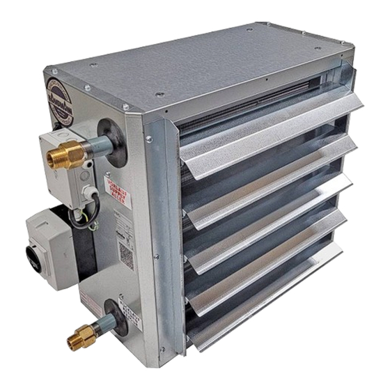
Assembly, installation and operating instructions Construction and function Overview Fig. 1: TOP at a glance Unit heater housing Louvre, single-row Fan guard Heat exchanger Repair switch Electrical junction box Brief description TOP are used for the decentralised local heating or cooling and ventilation of high-ceilinged buildings, either wall- or ceiling- mounted. -
Page 14: Installation And Wiring
Assembly, installation and operating instructions Installation and wiring Requirements governing the installation site Only install and assemble the unit if the following conditions are met: Make sure that the wall/ceiling is sufficiently load-bearing to take the weight of the unit (Technical data [} 12]). Make sure that the unit is securely suspended/standing. -
Page 15: Installation Of Sheet Steel Accessories
Assembly, installation and operating instructions Installation 2 people are needed to install the unit. CAUTION! Risk of injury from sharp metal housing! The inner metal of the casing can have sharp edges. Wear suitable protective gloves. IMPORTANT NOTE! Horizontal installation of units! When installing the units, ensure that they are completely horizontal to ensure proper operation. - Page 16 Assembly, installation and operating instructions Figure Description Dimensions [mm] (in) Suitable for KaMAX air outlet, type 3*111 All series Universal 4-point brackets, Series 44-47 type 30042 Ceiling/wall brackets, type Series 44-47 3*049 Universal bracket extension, All series type 30043...
- Page 17 Assembly, installation and operating instructions Figure Description Dimensions [mm] (in) Suitable for Wall bracket, type 34044 Series 44 40 (1.6) 50 (2.0) (23.0) (9.9) (6.3) (13.4) Wall bracket, type 35044 Series 45 40 (1.6) 50 (2.0) (23.0) (9.9) (6.3) (17.3) Wall bracket, type 36044 Series 46 40 (1.6)
- Page 18 Assembly, installation and operating instructions Figure Description Dimensions [mm] (in) Suitable for Universal 2-point brackets. Series 44-47 Type 30041 Universal 2-point T-beam Series 44-47 brackets, type 30047 Universal 2-point brackets, Series 48 type 38041 Universal 4-point brackets, Series 48 type 38042 Tab. 7: Air-side sheet steel accessories...
-
Page 19: Suspension Points
Assembly, installation and operating instructions 6.3.2 Suspension points Fig. 3: TOP suspension points Unit heater series A [mm] (in) B [mm] (in) 350 (13.8) 220 (8.7) 450 (17.7) 220 (8.7) 550 (21.7) 220 (8.7) 650 (25.6) 220 (8.7) 750 (29.5) 220 (8.7) Tab. 8: Suspension points for wall / ceiling installation 6.3.3 Universal 2-point brackets type 30041 Fig. 4: Universal 2-point brackets, series 44-47... -
Page 20: Universal 2-Point Brackets Type 38041
Assembly, installation and operating instructions 6.3.4 Universal 2-point brackets type 38041 Fig. 5: Universal 2-point brackets, series 48 6.3.5 Universal 4-point brackets type 30042 Fig. 6: Universal 4-point brackets, series 44-47... -
Page 21: Universal 4-Point Brackets Type 38042
Assembly, installation and operating instructions 6.3.6 Universal 4-point brackets type 38042 Fig. 7: Universal 4-point brackets, series 48 6.3.7 Universal 2-point T-brackets type 30047 Fig. 8: Universal 2-point T-brackets, series 44-47... -
Page 22: Wall Brackets, Type 3*044, Type 3002
Assembly, installation and operating instructions 6.3.8 Wall brackets, type 3*044, type 3002* Fig. 9: Wall brackets * Wall bracket, extended (type 3002*) 6.3.9 Ceiling to wall brackets type 3*049 Fig. 10: Ceiling to wall bracket installation... -
Page 23: Louvres
Assembly, installation and operating instructions 6.3.10 Louvres Fig. 11: Louvres Induction louvre mounting (type 3*101): A + B Induction louvre mounting, 2-row (type 3*002): A + C + D Installation Hydraulic connection Note the following points when connecting the hydraulic side: Install and test safety components (expansion vessels, pressure relief valves and overflow valves). -
Page 24: Connection To The Pipe Network
Assembly, installation and operating instructions 6.4.1 Connection to the pipe network Heat exchanger, galvanised steel, 1-layer Heat exchanger, copper/aluminium and galvanised, 2-layer Series A [mm] (in) 360 (14.2) 460 (18.1) 560 (22.0) 660 (26.0) 760 (30.0) The supply and return connections protrude laterally from the housing. The heat exchanger connection sizes for copper/alu- minium, galvanised steel heat exchangers are: 1"... -
Page 25: Electrical Connection
Assembly, installation and operating instructions Electrical connection IMPORTANT NOTE! Switch the unit on and off at the control input! Do not switch the unit on and off at the mains, since a fault message is generated for up to 10 seconds after the mains power is switched on! After this time, the EC fan's electronic circuit is ready for operation and a reliable status message is possible. -
Page 26: Maximum Electrical Rating Values
Assembly, installation and operating instructions Maximum electrical rating values Electromechanical model Type Nominal Mains fre- Active Nominal Leakage cur- MOP [A] IP class Protection voltage [V] quency [Hz] power [kW] current [A] rent [mA] class 44**56 208 - 240 0.14 1.45 - 1.20 <3.5 44**58... -
Page 27: Connection (**00)
Assembly, installation and operating instructions 7.2.1 Connection (**00) Power supply and control All sizes require a power supply in accordance with Max- imum electrical rating values [} 26] and can be con- trolled via a control input 0-10 VDC (Ri > 49 KOhm). Types 45xx58, 46xx58, 47xx5x and 48xx68 can alternatively be op- erated via an integral MODBUS RTU interface. - Page 28 1530004xxx88.. with rep. switch optional Type Standard 4xxx88.. Tel: +49 (0) 591 - 7108-0 Fax: 7108-300 SAP number Project Number / Project Origin 16163 E-Mail: info@kampmann.de 1872228 Index Revision Date Name mCAD Internet: www.kampmann.de Page Order Number COPYRIGHT RESERVED - Drawing contains information which has been developed by us and is protected. It must not be made...
- Page 29 Assembly, installation and operating instructions...
- Page 30 Assembly, installation and operating instructions...
-
Page 31: Pre-Commissioning Checks
Assembly, installation and operating instructions Pre-commissioning checks Before initial commissioning, check whether all the necessary conditions have been met so that the unit can operate safely and properly. Structural tests Check that the unit is securely standing and fixed. Check the horizontal installation/suspension of the unit. Check the completeness and correct seating of all filters (dirt side). -
Page 32: Maintenance
Assembly, installation and operating instructions Maintenance Securing against reconnection DANGER! Risk of death by unauthorised or uncontrolled restart! Unauthorised or uncontrolled restarting of the equipment can result in serious injury or death. Before restarting, ensure that all safety devices are fitted and working properly and that there is no haz- ard to humans. -
Page 33: Clean The Inside Of The Unit
Assembly, installation and operating instructions Clean the inside of the unit Check all elements that come into contact with air (internal surfaces of the unit, outlet elements etc.) for dirt or deposits dur- ing maintenance and use a commercially available product to remove. DANGER! Risk of injury from burning High temperatures are produced at the fan’s electronic housing. -
Page 34: Faults
Assembly, installation and operating instructions Faults The following chapter describes possible causes of faults and the work needed to rectify them. Should faults occur frequently, shorten the maintenance intervals in line with the actual loading on the unit. Contact the manufacturer with any faults that cannot be rectified using the following information. Behaviour in the event of faults The following applies: 1. - Page 35 Assembly, installation and operating instructions Status output via flash code The EC fans are blockage protected. Protective functions that trigger an automatic shut-off in case of a fault are integrated. These depend on the fan type. Viewing window for status LED Fig. 13: Flash code LED code Relay in the fan*...
-
Page 36: Fault Table
Assembly, installation and operating instructions 10.1 Fault table Fault Possible cause Remedy Check voltage, switch on repair switch. No function. No power supply. Replace fuse. Unit is switched off. Switch on the unit via the controller. No mains voltage or mains voltage does not cor- Check the power supply and restore, if neces- respond to the unit version. -
Page 37: Fault Table, Electromechanical Control Type
Assembly, installation and operating instructions 10.2 Fault table, electromechanical control type ..58/56/68 Fault Possible cause Remedy Switch off, de-energise and remove the mechan- Mechanical blockage. EC fan does not rotate when power is applied to ical blockage. the module and control signal > approx. 2 VDC Control voltage poles switched. -
Page 38: Table
Assembly, installation and operating instructions Table Tab. 1 Limits of operation ..............................7 Tab. 2 Maximum flow temperatures ..........................7 Tab. 3 Operating voltage ..............................7 Tab. 4 Water quality................................7 Tab. 5 Technical data, TOP..............................12 Tab. 6 Overview of types with minimum distances......................14 Tab. - Page 40 Country Contact Kampmann Heating, Cooling, Ventilation Ltd. 1625 Dilworth Drive Unit #207 Kelowna, BC Canada V1Y 8M4 Canada T +1 604/ 3621080 F +1 604/ 6871327 E info@kampmann.ca W Kampmann.ca...
Need help?
Do you have a question about the TOP 44 Series and is the answer not in the manual?
Questions and answers