
Subscribe to Our Youtube Channel
Related Manuals for Kampmann TOP EX Series


Summary of Contents for Kampmann TOP EX Series
- Page 1 TOP [EX] ► Assembly, installation and operating instructions Keep these instructions in a safe place for future use! Issue02/24EN SAP No.1924497...
-
Page 3: Table Of Contents
Table of contents 1 General ..........................5 1.1 About these instructions ........................1.2 Explanation of Symbols.......................... 2 Safety............................ 6 2.1 Correct use............................. 2.2 Special conditions of use........................2.3 Limits of operation and use........................2.4 Risk from electrocution!......................... 2.5 Personnel requirements - Qualifications ....................10 2.6 Personal Protective Equipment ...................... - Page 4 9 Maintenance ......................... 25 9.1 Securing against reconnection ....................... 25 9.2 Maintenance Schedule:.......................... 25 9.3 Clean the inside of the unit........................25 10 Certificates..........................27 10.1 Konformitätserklärung Top Ex-Schutz.pdf ..................28 10.2 Baugruppenerklärung Top Ex-Schutz.pdf..................... 29 10.3 EU_KONFORMITÄTSERKLÄRUNG_LUFTERHITZER_INT.PDF ..............30 Table .............................
-
Page 5: General
TOP [EX] Assembly, installation and operating instructions General About these instructions These instructions ensure the safe and efficient handling of this equipment. These instructions form an integral part of the equipment and have to be kept in the direct vicinity of the equipment and available to personnel at all times. All personnel must have carefully read through these instructions prior to commencing all work on the equipment. -
Page 6: Safety
TOP [EX] Assembly, installation and operating instructions Safety This section provides an overview of all important safety aspects to ensure optimum protection of personnel as well as safe and trouble-free operation. In addition to the safety instructions in these operating instructions, the valid safety, accident pre- vention and environmental protection regulations must be observed for the area of use of the unit. - Page 7 TOP [EX] Assembly, installation and operating instructions Limits of operation and use Limits of operation Min./max. water temperature °C 5 - see type plate Min./max. air intake temperature °C -20 - (+40) Min./max. air humidity 15-75 Min. operating pressure bar/kPa Max.
-
Page 8: Risk From Electrocution
TOP [EX] Assembly, installation and operating instructions WARNING! Note the maximum flow temperatures to protect the fan! Long periods of idleness with high water temperatures can lead to the impermissible heating up of the fan motor. The flow temperatures should therefore be limited depending on the application and the motor model. - Page 9 TOP [EX] Assembly, installation and operating instructions DANGER! Risk of fatal injury from electrocution! When multiple fans are connected in parallel, there is an electrical charge (>50 C) between the line con- ductor and protective earth conductor when the power is switched off. Before working on the electrical wiring, short-circuit the mains connections and PE! The terminals and connectors are still energised even when the unit is switched off.
-
Page 10: Personnel Requirements - Qualifications
TOP [EX] Assembly, installation and operating instructions Personnel requirements - Qualifications Expertise The installation of this product requires specialist heating, cooling, ventilation, installation and electrical knowledge. As this knowledge is normally acquired through vocational training in one of the above fields, it is not dealt with further here. Damage caused by improper installation is the responsibility of the operator or installer. -
Page 11: Transport, Storage And Packaging
IMPORTANT NOTE! Warranty claims can only be made within the applicable period for complaints. (More information is avail- able in the T&Cs on the Kampmann website) IMPORTANT NOTE! 2 people are needed to transport the unit. Wear personal protective clothing when transporting the unit. -
Page 12: Storage
TOP [EX] Assembly, installation and operating instructions Storage Store packaging under the following conditions: Do not store outdoors. Store in a dry and dust-free place. Store in a frost-free place. Do not expose to aggressive media. Protect from direct sunlight. Avoid mechanical vibrations and shocks. -
Page 13: Technical Data
TOP [EX] Assembly, installation and operating instructions Technical data Unit Series Water content [l] 1.6 - 6.1 2.2 - 8.2 3.4 - 11.5 4.8 - 16.8 Weight [kg] 25 - 62 32 - 92 45 - 125 53 - 158 Sound pressure level 13 - 56 19 - 64... -
Page 14: Construction And Function
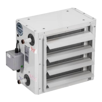
TOP [EX] Assembly, installation and operating instructions Construction and function Overview Fig. 1: TOP at a glance Fan guard Whisper-quiet sickle-blade fan Rear panel with nozzle Heat exchanger (example - copper/aluminium model) Unit heater housing Louvre, one-row (as standard) Brief description TOP unit heaters are used for the decentralised local heating or cooling and ventilation of halls, as wall or ceiling-mounted versions. -
Page 15: Installation And Wiring
TOP [EX] Assembly, installation and operating instructions Installation and wiring Requirements governing the installation site Only install and assemble the unit if the following conditions are met: Make sure that the wall/ceiling is sufficiently load-bearing to take the weight of the unit (Technical data [} 13]). Make sure that the unit is securely suspended/standing. -
Page 16: Installation
TOP [EX] Assembly, installation and operating instructions Installation CAUTION! Risk of injury from sharp metal housing! The inner metal of the casing can have sharp edges. Wear suitable protective gloves. IMPORTANT NOTE! Horizontal installation of units! When installing the units, ensure that they are completely horizontal to ensure proper operation. 6.3.1 Installation of sheet steel accessories Figure Description... - Page 17 TOP [EX] Assembly, installation and operating instructions Figure Description Dimensions [mm] Suitable for Wall bracket, type 34044 Series 44 Wall bracket, type 35044 Series 45 Wall bracket, type 36044 Series 46 Wall bracket, type 37044 Series 47 Wall brackets, extended, type Series 44 30022 Wall brackets, extended, type...
-
Page 18: Suspension Points
TOP [EX] Assembly, installation and operating instructions Figure Description Dimensions [mm] Suitable for Universal 2-point brackets. Type Series 44-47 30041 Tab. 7: Air-side sheet steel accessories 6.3.2 Suspension points Fig. 3: TOP suspension points Unit heater series A [mm] (in) B [mm] (in) 350 (13.8) 220 (8.7) 450 (17.7) -
Page 19: Universal 2-Point Brackets Type 30041
TOP [EX] Assembly, installation and operating instructions 6.3.3 Universal 2-point brackets type 30041 Fig. 4: Universal 2-point brackets, series 44-47 6.3.4 Universal 4-point brackets type 30042 Fig. 5: Universal 4-point brackets, series 44-47... -
Page 20: Wall Brackets, Type 3*044, Type 3002
TOP [EX] Assembly, installation and operating instructions 6.3.5 Wall brackets, type 3*044, type 3002* Fig. 6: Wall brackets * Wall bracket, extended (type 002*) 6.3.6 Louvres Fig. 7: Louvres Louvre mounting, 2-row (type *002): A + C + D... -
Page 21: Installation
TOP [EX] Assembly, installation and operating instructions Installation Hydraulic connection Note the following points when connecting the hydraulic side: Install and test safety components (expansion vessels, pressure relief valves and overflow valves). Route condensation lines with a sufficient cross-section without bends and narrow sections with a gradient to the in situ waste water pipe. -
Page 22: Electrical Connection
TOP [EX] Assembly, installation and operating instructions Electrical connection IMPORTANT NOTE! Motor protection Motor protection is provided by PTC thermistors embedded in the motor windings. The PTC thermistors are monitored by electronics in the stage switch type 30351. The stage switch is switched off as soon as the motor heats up unacceptably. -
Page 23: Maximum Electrical Rating Values
TOP [EX] Assembly, installation and operating instructions Maximum electrical rating values Electromechanical model Type Changeover Voltage [V] Current [A] Output [W] Fan speed [rpm] 44**37 D / Y 0.27/0.2 140/ 120 1420/ 1230 45**37 D / Y 0.6 /0.41 290/ 230 1390/ 1130 46**37 D / Y... -
Page 24: Pre-Commissioning Checks
TOP [EX] Assembly, installation and operating instructions Pre-commissioning checks When commissioning the device for the first time, ensure that all the necessary requirements are met so that the device can function safely and in accordance with its intended use. Structural tests Check that the unit is securely standing and fixed. -
Page 25: Maintenance
TOP [EX] Assembly, installation and operating instructions Maintenance Securing against reconnection DANGER! Risk of death by unauthorised or uncontrolled restart! Unauthorised or uncontrolled restarting of the equipment can result in serious injury or death. Before restarting, ensure that all safety devices are fitted and working properly and that there is no haz- ard to humans. - Page 26 Risk of explosion due to improper maintenance/repair Failure to carry out maintenance/repair work correctly can result in serious or even fatal injury. Only perform maintenance or repair work on units using original Kampmann GmbH & Co. KG spare parts in accordance with the relevant instructions.
-
Page 27: Certificates
TOP [EX] Assembly, installation and operating instructions Certificates... -
Page 28: Konformitätserklärung Top Ex-Schutz.pdf
EU-Konformitätserklärung gemäß Richtlinie 2014/34/EU (ATEX) Wir erklären hiermit als Hersteller in alleiniger Verantwortung, dass die nachfolgend beschriebenen Produkte der Richtlinie 2014/34/EU und den aufgeführten harmonisierten Normen entsprechen. Hersteller: Kampmann GmbH & Co. KG Friedrich-Ebert-Straße 128-130 49811 Lingen (Ems) Produkt: Top Lufterhitzer Typ 44**37, 45**37, 46**37, 47**37 Beschreibung: Sekundärluft-Temperiergerät zur Wand- oder Deckenmontage... -
Page 29: Baugruppenerklärung Top Ex-Schutz.pdf
Betroffene Produkte: Top Lufterhitzer Typ 44**37, 45**37, 46**37, 47**37 Wir, die Kampmann GmbH & Co. KG, erklären in alleiniger Verantwortung, dass die oben genannten Baugruppen der oben angegebenen Richtlinie entspricht und nur für die Verwendung als Lufterhitzer, in einer explosionsgefährdeten Umgebung entsprechend der resultierenden Kennzeichnungen aller verwendeter Baugruppen und nach deren bestimmungsgemäßer... -
Page 30: Eu_Konformitätserklärung_Lufterhitzer_Int.pdf
EU-Konformitätserklärung EU Declaration of Conformity Déclaration de Conformité CE Deklaracja zgodności CE EU prohlášení o konformite KAMPMANN Wir (Name des Anbieters, Anschrift): GMBH & Co. KG Friedrich-Ebert-Str. 128-130 We (Supplier’s Name, Address): 49811 Lingen (Ems) Nous (Nom du Fournisseur, Adresse): My (Nazwa Dostawcy, adres): My (Jméno dodavatele, adresa):... - Page 31 Gemäß den Bestimmungen der Richtlinien: Following the provisions of Directive: Conformément aux dispositions de Directive: Zgodnie z postanowieniami Dyrektywy: Odpovídající ustanovení směrnic: 2014/30/EU EMV-Richtlinie 2014/35/EU Niederspannungsrichtlinie 2009/125/EG ErP-Richtlinie 2016/2281 EU Durchführungsverordnung für Luftheizungsprodukte, Kühlungsprodukte, Prozesskühler mit hoher Betriebstemperatur und Gebläsekonvektoren Frank Bolkenius Lingen (Ems), den 06.03.2023 ______________________________...
-
Page 32: Table
TOP [EX] Assembly, installation and operating instructions Table Tab. 1 Limits of operation ..............................7 Tab. 2 Maximum flow temperatures ..........................7 Tab. 3 Operating voltage ..............................7 Tab. 4 Water quality................................7 Tab. 5 Technical data, ..............................13 Tab. 6 Overview of types with minimum clearances ...................... - Page 36 Land Kontakt Country Contact Kampmann GmbH & Co. KG Kampmann UK Ltd. Friedrich-Ebert-Str. 128 - 130 Dial House, Govett Avenue 49811 Lingen (Ems) Shepperton, Middlesex, TW17 8AG T +49 591/ 7108-660 T +44 1932/ 228592 Germany Great Britain F +49 591/ 7108-173 F +44 1932/ 228949 E export@kampmann.de...
Need help?
Do you have a question about the TOP EX Series and is the answer not in the manual?
Questions and answers