Table of Contents
Advertisement
Advertisement
Table of Contents

Related Manuals for Trace Engineering Legend


Summary of Contents for Trace Engineering Legend
- Page 1 Owner/Operator's Manual Part Number 3179...
- Page 3 Serial Number: _____________________________________ Purchase Date: _____________________________________ Comments: _____________________________________________________________________ _______________________________________________________________________________ _______________________________________________________________________________ _______________________________________________________________________________ _______________________________________________________________________________ _______________________________________________________________________________ Thank you for choosing Trace Engineering to meet your independent power needs. Check out our web site at www.traceengineering.com for more information and answers to your FAQ’ s.
-
Page 5: Table Of Contents
Table of Contents INTRODUCING THE LEGEND SERIES II.............1 IMPORTANT SAFETY INSTRUCTIONS...............2 ..................2 ENERAL RECAUTIONS ..................4 ERSONAL RECAUTIONS FEATURES ......................7 ..................7 ROTECTION IRCUITRY Automatic Low Battery Cut Out ...............7 Automatic High Battery Cut Out ..............7 High Temperature Cut Out ................7 Over Current Cut Out ..................8 Battery Type Optimization ................8... - Page 6 AC W ......................31 IRING AC and DC Wiring Separation ..............31 AC Wire Connections..................31 Ground Fault Interrupting Outlets (GFCI’ s)........... 33 Neutral-to-Ground Switching................. 35 Disabling Neutral Ground Switching ............. 37 OPERATION ......................38 BATTERIES ......................41 ....................41 ERMINOLOGY ........................
- Page 7 ................62 EMOTE ONTROL (BTS) .............63 ATTERY EMPERATURE ENSOR ....................63 ATTERY ABLES APPENDIX A: TROUBLESHOOTING..............65 APPENDIX B: OTHER PRODUCTS FROM TRACE ENGINEERING ....67 APPENDIX C: REFERENCE TABLES & GRAPHS..........69 ........69 YPICAL OWER ONSUMPTION OF OMMON PPLIANCES ..........70 NGLISH TO ETRIC ONVERSION HART ) ......70...
- Page 8 TABLE OF FIGURES Figure 1, Power Output Versus Temperature..............24 Figure 2, Battery to Inverter Cable Connection ..............26 Figure 3, DC Wiring Diagram..................30 Figure 4, AC Terminal Block....................31 Figure 5, AC Wiring Diagram ..................32 Figure 6, Typical Mobile Installation Diagram..............34 Figure 7, Neutral-to-Ground Switching without external AC source .......35 Figure 8, Neutral-to-Ground Switching with External AC ..........36 Figure 9, Disabling Neutral-to-Ground Switching ............37 Figure 10, Three-Stage Charging Profile .................52...
-
Page 9: Introducing The Legend Series Ii
I N T R O D U C I N G T H E L E G E N D S E R I E S I I Introducing the Legend Series II The Legend Series II inverter/chargers are specially designed for after market installation in recreational vehicles. -
Page 10: Important Safety Instructions
This manual covers inverters and inverter/chargers models: L2012, L2512, and L3012 Legend Series II inverter/chargers. The entire Legend series of inverters is UL listed to the general UL specification #458 covering power inverters for land vehicle applications. - Page 11 18. AC Grounding Instructions – The inverter/charger includes neutral to ground switching for the AC electrical system. The AC system in mobile installations must have the neutral physically isolated from the ground throughout the load distribution powered by the inverter. Trace Engineering Co. Inc. Tel (360) 435-8826 Part Number 3179...
-
Page 12: Personal Precautions
13. Clean battery terminals. Be careful to keep corrosion from coming in contact with eyes. 14. Study all battery manufacturer's specific precautions (such as removing or not removing cell caps while charging) and recommended rates of charge. Trace Engineering Co. Inc. Tel (360) 435-8826 Part Number 3179... - Page 13 15. Add ONLY distilled water in each cell until battery acid reaches level specified by battery manufacturer. This helps purge excessive gas from cells. Do not overfill. For a battery without cell caps, carefully follow manufacturer's recharging instructions. Trace Engineering Co. Inc. Tel (360) 435-8826 Part Number 3179...
-
Page 15: Features
This feature is called the Low Battery Cut Out (Auto LBCO). Your Legend inverter/charger comes from the factory with the Auto LBCO enabled; LBCO voltage is set at 11.1 volts. You can adjust the cutoff voltage to 8.5 volts (Auto LBCO disabled) using the optional RC7 remote control. -
Page 16: Over Current Cut Out
Example: 25 amps X 24 hours = 600 amp/hrs. Caution: Excessively high charge rates can overheat a battery. If battery bank capacity is low, set the battery charge rate to the minimum setting. Trace Engineering Co. Inc. Tel (360) 435-8826 Part Number 3179... -
Page 17: Shore Power Amps Monitoring
Search Mode Circuitry The Legend Series II inverters feature circuitry that minimizes power drain by reducing the inverter’ s output to small test pulses when there is no load connected to the inverter. These pulses are used to detect the presence of a load. -
Page 18: Impulse Phase Correction
Impulse phase correction provides a similar path for this ‘ backwards’ energy. The Legend line of inverter/chargers will run small motors at full speed, start larger ones, and run both efficiently. -
Page 19: Crystal Controlled Time Base
AC output while in the battery charger mode. The maximum power that can be handled by the inverter’ s internal wiring and transfer relay is 30 amps. Trace Engineering Co. Inc. Tel (360) 435-8826 Part Number 3179... -
Page 20: Unit Identification
U N I T I D E N T I F I C A T I O N Unit Identification This section describes the marking and location of the model and serial number for Legend Series II inverter/chargers. Use this section to determine the type and model of your inverter/charger. -
Page 21: Serial Number
Testing Laboratory Date of Manufacture Certification Number and Standards Identification Serial Number and Product Code: AV=3012, AW=2012, AX=2512 Trace Engineering Co. Inc. Tel (360) 435-8826 Part Number 3179 5916 195 Street, NE Fax (360) 435-2229 Effective August 6, 1998 Arlington, WA 98223 USA www.traceengineering.com... -
Page 23: Controls & Indicators
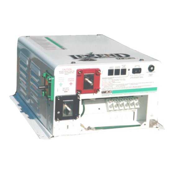
C O N T R O L S & I N D I C A T O R S Controls & Indicators The Legend Series II inverter/chargers feature a two-position On/Off rocker switch, tri-color status indicator, battery temperature sensor (BTS) port, remote control port, and a charger circuit breaker on the front panel. - Page 24 2. LED Indicator All Legend Series II inverter/chargers feature a tri-color LED on the front panel that will light green, orange, or red to indicate the operating mode, battery or charger status, or an error condition.
- Page 25 4. Stacking Port (not used). The Series II model is not a stackable unit. 5. Remote Control Port: The Legend Series II can be controlled up to 50 feet from the unit by plugging in a remote control (RC6 or RC7). See the Options section for a complete description of the RC6 and RC7 remote controls.
- Page 26 C O N T R O L S & I N D I C A T O R S 12. Charger Circuit Breaker: 25 amps in the L2012 and L2512, 30 amps in the L3012. Press breaker to reset. Trace Engineering Co. Inc. Tel (360) 435-8826 Part Number 3179...
-
Page 27: Quick Install
• Connect a cable from the positive battery terminal to the positive buss of your DC load center. • Ground all of your DC loads to your vehicle’ s chassis, or connect a cable from the ground bus of the DC load center to the vehicle chassis. Trace Engineering Co. Inc. Tel (360) 435-8826 Part Number 3179... - Page 28 • Connect the green wire from the ground of the AC power source to one of the two green wires (AC Safety Ground) bolted to the chassis of the inverter/charger. CAUTION Trace Engineering Co. Inc. Tel (360) 435-8826 Part Number 3179...
- Page 29 • Check to see that the inverter front panel switch is in the “ Off” position, then reconnect to the AC power source. • Turn the inverter to the “ On” position and check inverter operation (See Operation section) Trace Engineering Co. Inc. Tel (360) 435-8826 Part Number 3179...
-
Page 31: Installation
In this portion of the manual, we will look at requirements and recommendations for installing a Legend Series II inverter/charger. Keep in mind that these are only guidelines. Common sense, the National Electrical Code and local building codes are the final authority. -
Page 32: Mounting
1 ½ - inches is maintained around the sides of the inverter, and three inches at the back of the inverter with the cooling fan, adequate ventilation should be maintained. Because the top of a Legend Series II inverter is not vented, clearance between the enclosure and the top of the inverter is not relevant. -
Page 33: Dc Wiring
AC power, c) disconnect the battery cables. DC Cabling Connections Color-code your battery cables with colored tape or heat shrink tubing. The standard is red for positive (+) and black for negative (-). Trace Engineering Co. Inc. Tel (360) 435-8826 Part Number 3179 5916 195... -
Page 34: Figure 2, Battery To Inverter Cable Connection
2/0 Copper Compression Lug Figure 2, Battery to Inverter Cable Connection Figure 2, Battery to Inverter Cable Connection illustrates proper connections for the Legend Series II inverter/chargers. Points of caution are: ü Do not connect the battery negative (-) terminal to the vehicle chassis; connect it to the battery negative terminal of the inverter. -
Page 35: Ground Cable Connection
250 MCM Lug Ground Cable Connection You probably noticed that the Trace Legend Series II inverter/chargers have a third battery terminal labeled “ Vehicle Chassis Ground” (the green terminal on the left side of the unit). The purpose of this third terminal is be sure that all DC load current into or out of the battery bank will flow through the internal shunt of the inverter. -
Page 36: Battery Cable Sizing
These installation parts are not supplied as part of the inverter. However, Trace Engineering offers a DC-rated class T fuse and safety-covered fuse block which are compatible with the Legend Series II Trace Engineering Co. Inc. Tel (360) 435-8826... -
Page 37: Table 2, Current Carrying Ability Of Wire In Free Air At 75°C
170 amps 175 Amp 00 AWG 265 amps 300 Amp 360 amps 400 Amp 0000 AWG Trace Engineering Co. Inc. Tel (360) 435-8826 Part Number 3179 5916 195 Street, NE Fax (360) 435-2229 Effective August 6, 1998 Arlington, WA 98223 USA www.traceengineering.com... -
Page 38: Figure 3, Dc Wiring Diagram
Fuse Block DC Load Distribution Panel Out to DC loads Figure 3, DC Wiring Diagram Trace Engineering Co. Inc. Tel (360) 435-8826 Part Number 3179 5916 195 Street, NE Fax (360) 435-2229 Effective August 6, 1998 Arlington, WA 98223 USA www.traceengineering.com... -
Page 39: Ac Wiring
Stranded copper wire is required. As a plus, stranded wire is generally much more flexible and thus easier to work with. Trace Engineering Co. Inc. Tel (360) 435-8826 Part Number 3179... -
Page 40: Figure 5, Ac Wiring Diagram
CONNECT AC HOT IN TO AC HOT IN 1 CONNECT AC HOT OUT TO AC HOT OUT 1 TYPICAL 120/240VAC 3 WIRE ELECTRICAL SYSTEM DIAGRAM Figure 5, AC Wiring Diagram Trace Engineering Co. Inc. Tel (360) 435-8826 Part Number 3179 5916 195... -
Page 41: Ground Fault Interrupting Outlets (Gfci' S)
This is easiest to do at the sub-panel by isolating the neutral connector block from the frame of the subpanel with an appropriate insulator. Ground Fault Interrupting Outlets (GFCI’ s) Trace Engineering has tested the following GFCI’ s and found them to work satisfactorily with our inverters: LEVITON 6599 PASS &... -
Page 42: Figure 6, Typical Mobile Installation Diagram
Battery Isolator Vehicle House Battery Alternator Vehicle Starting Bank Battery Figure 6, Typical Mobile Installation Diagram Trace Engineering Co. Inc. Tel (360) 435-8826 Part Number 3179 5916 195 Street, NE Fax (360) 435-2229 Effective August 6, 1998 Arlington, WA 98223 USA www.traceengineering.com... -
Page 43: Neutral-To-Ground Switching
I N S T A L L A T I O N Neutral-to-Ground Switching All of the Legend Series units employ neutral to ground switching as required by the NEC (National Electric Code). The purpose for this requirement is to ensure that the neutral conductor in a three- wire system is "bonded"... -
Page 44: Figure 8, Neutral-To-Ground Switching With External Ac
Neutral-to-Ground “BOND” is provided by the NEUTRAL external AC source for entire AC system GROUND Figure 8, Neutral-to-Ground Switching with External AC Trace Engineering Co. Inc. Tel (360) 435-8826 Part Number 3179 5916 195 Street, NE Fax (360) 435-2229... -
Page 45: Disabling Neutral Ground Switching
GFCI’ s (Ground Fault Circuit Interrupter). Disabling Neutral Ground Switching Legend inverters employ neutral-to-ground switching. In countries such as Canada this may be utilized, and therefore may need to be disabled before installation. Check local code if you are not sure whether you must disable the neutral ground switching feature. -
Page 46: Operation
This delay also allows time for a generator to spin up to a stable operating condition before connecting to the inverter. In this manner relay chatter is reduced. Trace Engineering Co. Inc. Tel (360) 435-8826 Part Number 3179... - Page 47 A: Troubleshooting will help you solve problems you encounter. If any of the inverter’ s internal setpoints are to be adjusted, consult the booklet included with the RC7 remote control. Trace Engineering Co. Inc. Tel (360) 435-8826 Part Number 3179...
-
Page 49: Batteries
An optional temperature-probe (BTS) automatically re-scales charge-voltage settings to compensate for ambient temperatures. The compensation slope based on cell voltage is -2.17mv per degree Fahrenheit per cell (30mv per degree Celsius) for lead-acid batteries. Trace Engineering Co. Inc. Tel (360) 435-8826 Part Number 3179 5916 195... -
Page 50: Types
This is the minimum quality of battery that should be used with the Legend Series II inverter in normal applications. Some systems use the L16 type of battery. These are 6-volt batteries rated at 350 amp-hours and are available from a number of manufacturers. -
Page 51: Environment
If the system is located in an unheated space, an insulated enclosure is highly recommended for the batteries. During the charging process, the batteries release heat due to the internal resistance of Trace Engineering Co. Inc. Tel (360) 435-8826 Part Number 3179... -
Page 52: Battery Bank Sizing
Manufacturer literature may provide more accurate information compared to the motor nameplate. If large motors will be started, increase the battery size to allow for the high demand start-ups require. Trace Engineering Co. Inc. Tel (360) 435-8826 Part Number 3179... -
Page 53: Battery Bank Sizing Example & Worksheet
Inverter: This is the minimum inverter size required. Add together the appliances that will run at the same time from Column 3 (Appliance Watts, listed above). You will need an inverter with this many watts or more. Trace Engineering Co. Inc. Tel (360) 435-8826 Part Number 3179... -
Page 54: Table 4, Typical Appliance Watts
One FL Light Blender Computer Toaster 1000 Television 100-500 Hot Plate 1800 Microwave Washer/Dryer 375-1000 Trace Engineering Co. Inc. Tel (360) 435-8826 Part Number 3179 5916 195 Street, NE Fax (360) 435-2229 Effective August 6, 1998 Arlington, WA 98223 USA www.traceengineering.com Page... -
Page 55: Monthly Maintenance
½-inch or 9/16 wrench as required, or an equivalent socket and ratchet • adjustable and/or locking pliers • torque wrench (suggested, not required) • soft-bristled brush (discarded toothbrushes work just fine) • 6-inch scrub brush Trace Engineering Co. Inc. Tel (360) 435-8826 Part Number 3179 5916 195 Street, NE... -
Page 56: Equipment
If any white powdery residue forms between the battery cable lug and the battery terminal, the cable must be removed for cleaning. When it is necessary to detach a battery cable from the battery, Trace Engineering Co. Inc. Tel (360) 435-8826... -
Page 57: Cables
Connect several smaller batteries together when creating a battery bank of substantial size. There are three ways to do this. Batteries can be connected in parallel, series, or series - parallel. Trace Engineering Co. Inc. Tel (360) 435-8826 Part Number 3179... -
Page 58: Parallel Connection
CAPACITY: BANK CAPACITY: 200 AMP-HOURS 200 AMP-HOURS 24V INVERTER @ 6 VDC @ 24 VDC Trace Engineering Co. Inc. Tel (360) 435-8826 Part Number 3179 5916 195 Street, NE Fax (360) 435-2229 Effective August 6, 1998 Arlington, WA 98223 USA www.traceengineering.com... -
Page 59: Series - Parallel Connection
Read the important safety instructions at the start of this manual and the battery supplier’ s precautions before installing the inverter and batteries. Trace Engineering Co. Inc. Tel (360) 435-8826 Part Number 3179 5916 195... -
Page 60: Three-Stage Battery Charger
Charging Profile The battery charger in the Trace Legend Series II inverters charges in three stages - BULK, ABSORPTION, and FLOAT - to provide rapid and complete charge cycles without undue battery gassing. The figure below shows how DC voltage and current change with time through the different charge stages. - Page 61 Note When DC loads are placed on the battery, the charger will deliver currents up to the Maximum Charge Rate setting while maintaining the float voltage. Trace Engineering Co. Inc. Tel (360) 435-8826 Part Number 3179 5916 195...
-
Page 62: Generator Requirements
3000 VA models). Smaller generators will have the tops of their waveform clipped under such loads. Running at these reduced peak voltages will not harm the charger, but it will limit the maximum charge rate. Large auxiliary AC loads may exacerbate this problem. Trace Engineering Co. Inc. Tel (360) 435-8826 Part Number 3179... -
Page 63: Theory Of Inverter Operation
These pulses are then applied to a power transformer which steps the low voltage DC pulses up to higher voltage AC. In the Legend Series II inverter, this process is overseen by an onboard microcomputer. The computer is also responsible for the monitoring and charging of the battery bank, as well as monitoring and protecting the inverter/charger against damage from heat, over current, and other potentially hazardous situations. -
Page 64: Regulation
Peak Voltage Nominal battery High battery Low battery voltage voltage voltage Figure 13, RMS Voltage Regulation Trace Engineering Co. Inc. Tel (360) 435-8826 Part Number 3179 5916 195 Street, NE Fax (360) 435-2229 Effective August 6, 1998 Arlington, WA 98223 USA www.traceengineering.com... -
Page 65: Applications
If a motor fails to start within a few seconds, or it begins to lose power after running for a time, it should be turned off. When the inverter attempts to start a load that is greater than it can handle, it will turn itself off after about 10 seconds. Trace Engineering Co. Inc. Tel (360) 435-8826 Part Number 3179... -
Page 66: Problem Loads
A P P L I C A T I O N S Problem Loads Trace Engineering inverters can drive nearly every type of load. However, there are special situations in which inverters may behave differently than public power. Trace has provided the following knowledge as guidelines only. - Page 67 “ Black & Decker” ™ Dustbusters and Spotlighters work well. Laser printers- While many laser products are presently operating from Trace Engineering inverters, and we have personally run a Texas Instruments Microlaser and HP IIP, we have had reports of an HP III and a MacIntosh Laser Writer failing under inverter power.
-
Page 69: Options
The RC6 Remote Control The optional RC6 remote control unit duplicates the Power On/Off Switch on the Legend Series II inverter/charger. It connects directly to the port labeled Remote Control on the front of the inverter, using standard phone cable and jacks. -
Page 70: The Rc7 Remote Control
The RC7 Remote Control The optional RC7 remote control has the ability to communicate and adjust settings in the Legend Series II. It connects into the port labeled Remote Control on the front panel of the inverter using the included remote connection cable. -
Page 71: Battery Temperature Sensor (Bts)
2/0 and 4/0. Cable lengths include 1½, 3, 5, and 10 feet for both sizes. A 4/0 cable length of 15 feet is also available. All Trace Engineering cables have red or black color-coding, and sealed, crimped ring terminal ends. -
Page 73: Appendix A: Troubleshooting
(most are not). Low surge power Weak batteries, battery cables Refer to cable and battery too small or too long recommendations in owner’ s manual Trace Engineering Co. Inc. Tel (360) 435-8826 Part Number 3179 5916 195 Street, NE Fax (360) 435-2229... -
Page 75: Appendix B: Other Products From Trace Engineering
AC loads. An AC system bypass allows AC loads to operate while the inverter is locked out for servicing. Contact your Trace Engineering dealer for details on any of the above products. Trace Engineering Co. Inc. -
Page 77: Appendix C: Reference Tables & Graphs
Keep this in mind when sizing a motor into a system. Refrigerators and icemakers typically run about 1/3 of the time. Therefore, their average battery current draw is 1/3 what their amp rating would indicate. Trace Engineering Co. Inc. Tel (360) 435-8826 Part Number 3179... -
Page 78: English To Metric Wire Conversion Chart
"Free air" is defined by the NEC as cabling that is not enclosed in conduit or a raceway. Cables enclosed in raceways or conduits have substantially lower continuous current carrying ability due to heating factors. Trace Engineering Co. Inc. Tel (360) 435-8826 Part Number 3179... -
Page 79: Recommended Minimum Ac Wire Sizes
Float Volts Gelled Lead-Acid (sealed ) 14.1 volts 13.5 volts Liquid Lead-Acid (not-sealed) 14.5 volts 13.4 volts Trace Engineering Co. Inc. Tel (360) 435-8826 Part Number 3179 5916 195 Street, NE Fax (360) 435-2229 Effective August 6, 1998 Arlington, WA 98223 USA www.traceengineering.com... -
Page 80: Legend Series Ii Charging Graph
A P P E N D I X C : R E F E R E N C E T A B L E S & G R A P H S Legend Series II Charging Graph LEGEND CHARGE CURVE 14.5... -
Page 81: Legend Series Ii Efficiency Curve
A P P E N D I X C : R E F E R E N C E T A B L E S & G R A P H S Legend Series II Efficiency Curve L2012 L2512 L3012 Output Power In Watts X 100 Trace Engineering Co. -
Page 82: Legend Performance Graph
A P P E N D I X C : R E F E R E N C E T A B L E S & G R A P H S Legend Performance Graph POWER VS. TIME 7000 6000... -
Page 83: Appendix D: Specifications
Altitude Non-operating 50,000 feet Dimensions 13.15” x 7.25” x 14.3” 33.3cm x 18cm x 35.2cm Mounting Shelf mount only Trace Engineering Co. Inc. Tel (360) 435-8826 Part Number 3179 5916 195 Street, NE Fax (360) 435-2229 Effective August 6, 1998 Arlington, WA 98223 USA www.traceengineering.com... - Page 84 Charge Rate 100% of maximum VAC dropout 40 VAC Shorepower Amps All Specifications Subject to Change Without Notice Trace Engineering Co. Inc. Tel (360) 435-8826 Part Number 3179 5916 195 Street, NE Fax (360) 435-2229 Effective August 6, 1998 Arlington, WA 98223 USA www.traceengineering.com...
-
Page 85: Appendix E: Dimensions
A P P E N D I X E : D I M E N S I O N S Appendix E: Dimensions 12.375” CAUTION 13.15" Note: teminals and covers add 1 1/2” to length Trace Engineering Co. Inc. Tel (360) 435-8826 Part Number 3179 5916 195 Street, NE Fax (360) 435-2229... -
Page 87: Appendix F: Limited Warranty
(4) in components, parts, or products expressly warranted by another manufacturer. Trace Engineering agrees to supply all parts and labor or repair or replace defects covered by this warranty with parts or products of original or improved design, at its option, if the defective product is... - Page 88 Warranty Procedure Complete the warranty card and mail it to Trace Engineering within 10 days from the date of purchase. KEEP YOUR BILL OF SALE as proof of purchase, should any difficulties arise concerning the registration of the warranty card.
- Page 89 Products sent to the factory from outside the U.S. MUST include return freight funds, and sender is fully responsible for all customs documents, duties, tariffs, and deposits. Record the model and serial numbers on the Packaging Materials sheet and retain for your files. Trace Engineering Co. Inc. Tel (360) 435-8826 Part Number 3179...
-
Page 90: Appendix G: Life Support Policy
Appendix G: Life Support Policy As a general policy, Trace Engineering, Inc. does not recommend the use of any of its products in life support applications where failure or malfunction of the Trace Engineering product can be reasonably expected to cause failure of the life support device or to significantly affect its safety or effectiveness. -
Page 91: Index
Free Air ............28 Fuse Block part number..........29 Cable ends............26 fuse size............28, 29 Charge Rate ...........75 Charger Circuit Breaker ........18 Trace Engineering Co. Inc. Tel (360) 435-8826 Part Number 3179 5916 195 Street, NE Fax (360) 435-2229 Effective August 6, 1998 Arlington, WA 98223 USA www.traceengineering.com... - Page 92 LEVITON ............33 life support devices......... 82 parallel............49, 50 Life Support Policy.......... 82 parallel connection.......... 50 PASS & SEYMOR .......... 33 Trace Engineering Co. Inc. Tel (360) 435-8826 Part Number 3179 5916 195 Street, NE Fax (360) 435-2229 Effective August 6, 1998 Arlington, WA 98223 USA www.traceengineering.com...
- Page 93 ........See waveforms wire Specifications..........75 stranded copper ..........31 square wave....... See waveforms Wiring Separation ...........31 Stacking Port ..........17 Trace Engineering Co. Inc. Tel (360) 435-8826 Part Number 3179 5916 195 Street, NE Fax (360) 435-2229 Effective August 6, 1998 Arlington, WA 98223 USA www.traceengineering.com...
Need help?
Do you have a question about the Legend and is the answer not in the manual?
Questions and answers
how do you clear error light and alarm from remote control
To clear the error light and alarm on the Trace Engineering Legend remote control, follow these steps:
1. Identify the Error – Check the LED indicators on the remote control to determine the cause of the alarm (e.g., low battery voltage, high temperature, etc.).
2. Resolve the Issue – Address the underlying problem based on the error type:
- If the battery voltage is too low or high, check and adjust the battery condition.
- If there is a high-temperature warning, allow the unit to cool down.
- Ensure all connections (battery and AC output) are secure and clean.
3. Reset the Inverter – Turn the inverter off, wait a few seconds, and turn it back on.
4. Monitor the System – Observe the LED indicators to confirm the error is cleared.
If the issue persists, further troubleshooting may be required.
This answer is automatically generated