Table of Contents
Advertisement
Quick Links
PS Series Inverter/Chargers
AE Configuration - Revision 5 Software
Owner's Manual
Copyright © Trace Engineering Company, Inc.
Telephone: 360/435-8826
PS Series Inverter/Charger
Fax: 360/435-2229
Part No. 3597
5916 - 195th Street N. E.
Arlington, WA 98223
www.traceengineering.com
Rev. D: November 23, 1999
Advertisement
Table of Contents

Related Manuals for Trace Engineering PS Series


Summary of Contents for Trace Engineering PS Series
- Page 1 PS Series Inverter/Chargers AE Configuration - Revision 5 Software Owner’s Manual Copyright © Trace Engineering Company, Inc. Telephone: 360/435-8826 PS Series Inverter/Charger Fax: 360/435-2229 Part No. 3597 5916 - 195th Street N. E. Arlington, WA 98223 www.traceengineering.com Rev. D: November 23, 1999...
-
Page 3: Table Of Contents
SPECIFICATIONS AND FEATURES............................117 DIMENSIONS...................................118 INSTALLATION DIAGRAMS ..............................120 USER SETTINGS WORKSHEET.............................122 APPENDIX ....................................127 OPTIONS....................................127 OTHER PRODUCTS ................................129 Copyright © Trace Engineering Company, Inc. Page Telephone: 360/435-8826 PS Series Inverter/Charger Fax: 360/435-2229 Part No. 3597 5916 - 195th Street N.E. Arlington, WA 98223 www.traceengineering.com... - Page 4 Figure 36, PS Series Dimensions .............................118 Figure 37, PS Series Bottom Plate Mounting Dimensions ......................119 Figure 38, PS Series – Showing Knockout Sizes for AC Wiring ....................119 Figure 39, PS Series Installation Diagram – Stationary Backup System..................120 Figure 40, PS Series Installation Schematic ..........................121 Figure 41, AWG Wire Size...............................131...
-
Page 5: Important Safety Instructions
Protect the inverter from splashing if used in vehicle applications. 4. Use of an attachment not recommended or sold by Trace Engineering for the PS Series Inverter/Charger may result in a risk of fire, electric shock, or injury to persons. -
Page 6: Personal Precautions
10. If a remote or automatic generator start system is used, disable the automatic starting circuit and/or disconnect the generator from its starting battery while performing maintenance to prevent accidental starting. Page Copyright © Trace Engineering Company, Inc. Telephone: 360/435-8826 PS Series Inverter/Charger Fax: 360/435-2229 Part No. -
Page 7: Introduction
Customer Service at (360) 435-8826. • Complete the warranty card and mail it to Trace Engineering within 10 days from the date of purchase Keep your bill of sale as proof of purchase, should any difficulties arise concerning the registration of the warranty card. - Page 8 INTRODUCTION Copyright © Trace Engineering Company, Inc. Page Telephone: 360/435-8826 PS Series Inverter/Charger Fax: 360/435-2229 Part No. 3597 5916 - 195th Street N.E. Arlington, WA 98223 www.traceengineering.com Rev. D: November 23, 1999...
-
Page 9: Unit Identification
CONTROLS, INDICATORS AND COMPONENTS UNIT IDENTIFICATION This section describes the marking and location of the model and serial number for the PS Series Inverter/Chargers. Use this section to determine the type and model of your inverter/charger. The unit Identification Label on the left side panel of the inverter/charger will show the model number, serial number, DC charging current (maximum and default setting), AC voltage and frequency, configuration, and date of manufacture. -
Page 10: Model Number
CERTIFICATION Figure 2, Certification Label The 120 VAC/60 Hertz models of the PS Series Inverter/Chargers (AE Configured) are Listed to UL Standard 1741, Power Conditioning Units for use in Residential and Commercial Photovoltaic Power Systems. This label is your guarantee that this inverter/charger has been tested by UL to nationally recognized Safety Standards and found to be free from reasonably foreseeable risk of fire, electric shock and related hazards. -
Page 11: Controls, Indicators And Components
CONTROLS, INDICATORS AND COMPONENTS CONTROLS, INDICATORS AND COMPONENTS Shown below are the controls and indicators on the PS Series Inverter/Charger. They enable you to control and monitor the operating mode and system status of your inverter/charger. The controls on the PS Series Inverter/Chargers are very straightforward. -
Page 12: Inverter/Charger Circuit Breaker
Figure 4, ‘Maximum AC Amps In’ Switch And LED Status Indicators LED STATUS INDICATORS All PS Series Inverter/Chargers feature four LED status indicators - located on the unit’s front side panel - that will enable you to monitor the operating mode and system status of your inverter/charger by lighting one or more of the LED’s. - Page 13 While the inverter has shut down, AC power from any AC source may not continue to pass through the inverter to power AC loads. Any power management provided by the inverter will not be able to occur while the inverter is off. Copyright © Trace Engineering Company, Inc. Page Telephone: 360/435-8826...
- Page 14 BULK VOLTS DC setting for the time period of the ABSORPTION TIME setting, at which time it then regulates the charging process at the FLOAT VOLTS DC setting. Copyright © Trace Engineering Company, Inc. Page Telephone: 360/435-8826...
-
Page 15: Ac Side
AC Ground Terminal (located inside) Figure 5, PS Series AC Side AC CIRCUIT BOARD By removing the Access Panel, you will be able to gain access to the AC circuit board, which includes the AC terminal block and four RJ11 jacks for connecting specific optional components. -
Page 16: Figure 7, Ac Terminal Block
This manual is specific to models designed for use in Alternative Energy or Back-Up Power systems in permanent structures, such as homes and commercial buildings. All of the PS Series units marked with the Alternative Energy configuration are designed with the three NEUTRAL terminals being common to each other and can be used in any combination or order. -
Page 17: Dc Side
INVERTERS section on page 92 for more information. REMOTE PORT The PS Series can be controlled remotely from the unit by plugging in a SWRC remote control or SWCA communications adapter. See the OPTIONS section starting on page 127 for a complete description of the SWRC and SWCA. - Page 18 CONTROLS, INDICATORS AND COMPONENTS Copyright © Trace Engineering Company, Inc. Page Telephone: 360/435-8826 PS Series Inverter/Charger Fax: 360/435-2229 Part No. 3597 5916 - 195th Street N.E. www.traceengineering.com Rev. D: November 23, 1999 Arlington, WA 98223...
-
Page 19: Installation
INSTALLATION INSTALLATION This section is very important, since it tells you how to properly install your PS Series Inverter/Charger. It becomes very frustrating when your inverter system does not perform properly, simply because care was not taken during installation. Please read this entire section carefully. You will save time and avoid common mistakes. -
Page 20: Mounting
1-½ inches around the top and 3 inches of clearance at the right side of the inverter will provide adequate ventilation. Because the bottom of the PS Series chassis is not vented, clearance between the enclosure and the bottom of the inverter is not critical. A fresh air intake port should be provided directly to the right side and an exhaust port on the top side will allow cool outside air to flow through the inverter and back out of the enclosure. -
Page 21: Figure 11, Ac Wire Connections
* The term "free air" is defined by the NEC as cabling that is not enclosed in conduit or a raceway. Cables enclosed in raceways or conduits have substantially lower continuous current carrying ability due to heating factors. Copyright © Trace Engineering Company, Inc. Page Telephone: 360/435-8826... - Page 22 The knockout sizes are shown in Figure 38, PS Series – Showing Knockout Sizes for AC Wiring on page119. Using appropriate conduit connectors, fasten the conduit to the inverter. Feed all AC wiring through the conduit and into the inverter AC terminal block.
-
Page 23: Dc Wiring
#4/0 AWG / 107 mm PS2212E 235 amps #2/0 AWG / 67.4 mm #4/0 AWG / 107 mm #4/0 AWG / 107 mm Copyright © Trace Engineering Company, Inc. Page Telephone: 360/435-8826 PS Series Inverter/Charger Fax: 360/435-2229 Part No. 3597 5916 - 195th Street N.E. -
Page 24: Table 3, Battery Cable To Maximum Breaker/Fuse Size
DC load disconnects, PV array disconnects, etc. and the top is designed to allow direct connection of up to two Trace Engineering charge controllers. The Trace DC disconnect is not designed to accept doubled (paralleled) cables which may be required for long cable runs. -
Page 25: Figure 13, Battery To Inverter Cable Connection
1-½ to 10 feet, and in 2/0 or 4/0 AWG. They are color-coded and have pressure crimped, sealed ring terminals. Contact your Trace Engineering dealer to order. Figure 13, illustrates the proper method to connect the battery cables to the PS Series Inverter/Charger. -
Page 26: System Grounding
In some countries, the neutral is not bonded to the grounding system. This means you may not know when a fault has occurred since the overcurrent device will not trip unless a “double” fault occurs. In some marine electrical codes, this type of system is also used. Copyright © Trace Engineering Company, Inc. Page Telephone: 360/435-8826... -
Page 27: Figure 14, Multiple Point Ground System
Zero Voltage Difference Difference Difference across Component Grounds Figure 14, Multiple Point Ground System Figure 15, Single Point Ground System Copyright © Trace Engineering Company, Inc. Page Telephone: 360/435-8826 PS Series Inverter/Charger Fax: 360/435-2229 Part No. 3597 5916 - 195th Street N.E. -
Page 28: Quick Install
This section is provided for installers, licensed electrical contractors, and knowledgeable laymen as a quick reminder on the essential steps to quickly install the Trace PS Series Inverter/Charger. If you haven’t had experience with the PS Series Inverters/Charger, you are urged to read the entire INSTALLATION section before installing the inverter/charger. -
Page 29: Functional Test
6. This completes the functional test, if all areas pass, the inverter is ready for use. If any of the inverter’s internal setpoints are to be adjusted, consult the MENU SYSTEM section starting on page 29. Copyright © Trace Engineering Company, Inc. Page... - Page 30 FUNCTIONAL TEST Copyright © Trace Engineering Company, Inc. Page Telephone: 360/435-8826 PS Series Inverter/Charger Fax: 360/435-2229 Part No. 3597 5916 - 195th Street N.E. Arlington, WA 98223 www.traceengineering.com Rev. D: November 23, 1999...
-
Page 31: Menu System
The PS Series Inverter/Charger MENU SYSTEM can ONLY be accessed and adjusted by using a SWRC Remote Control or SWCA Communications Adapter (see OPTIONS on page 127 for more information on the SWCA). -
Page 32: User Menu Map
AC source aux relays during charge or Sell or passthru Reset in 3 min. END USER MENU Copyright © Trace Engineering Company, Inc. Page Telephone: 360/435-8826 PS Series Inverter/Charger Fax: 360/435-2229 Part No. 3597 5916 - 195th Street N.E. -
Page 33: Setup Menu Map
Note: The values shown are the values for a 12 VDC – 120VAC/60HZ model. Multiply the DC settings by 2 for 24 VDC models. See the USER and SETUP menu item descriptions and default values for other models. Copyright © Trace Engineering Company, Inc. Page... -
Page 34: Swrc Remote Control
MENU SYSTEM SWRC REMOTE CONTROL The optional SWRC remote control has the ability to communicate and adjust settings in the PS Series inverter. It connects into the port labeled REMOTE CONTROL (SWRC/SWCA) on the DC side of the inverter using the included DB-25 remote connection cable and is operational whenever DC power is applied to the inverter DC input terminals. - Page 35 If the EQ mode is selected from the SET GENERATOR menu item under the GENERATOR MODE (2) menu heading, the BULK LED will slowly blink while the charger completes the equalization process. Copyright © Trace Engineering Company, Inc. Page Telephone: 360/435-8826...
- Page 36 Once a menu heading is selected, the MENU ITEM buttons are used to move up or down through the list of related menu items. The SET POINTS buttons change the value of a parameter or select a mode, for the selected menu item. Copyright © Trace Engineering Company, Inc. Page Telephone: 360/435-8826...
-
Page 37: User Menu
This menu heading is used only if a generator is included and controlled by the inverter. Provides information for accessing Trace Engineering. Also provides the Trace software revision number and allows resetting to the factory default values. - Page 38 ON - Starts the generator that is controlled by the inverter. If this position is selected, it will manually turn on the generator that is connected to the GEN CONTROL relays. The OFF position must be selected to manually turn the generator off. Copyright © Trace Engineering Company, Inc. Page Telephone: 360/435-8826...
- Page 39 CHARGE (orange) LED - BULK or FLOAT LED on the SWRC - has turned on. The acceptable frequency range is 53 to 67 Hertz for 60-Hertz models. Copyright © Trace Engineering Company, Inc. Page...
- Page 40 Move cursor to GEN OFF to reset generator error. If no start in 5 trys then error. If Gen runs for more than max run time then error. Under/Over speed will cause a Sync (Gen stopped due to V/F) error in 10 minutes MENU HEADING - TRACE ENGINEERING (3) Press reset now for defaults Allows resetting of all menu item settings to the factory default values.
- Page 41 Reads the RMS value of the AC voltage at the inverter's AC HOT IN and AC NEUTRAL IN terminals with the ‘MAXIMUM AC AMPS IN’ switch in AC2 position. This is usually the switch position for a back-up, fuel-powered generator. Value will drift around before inverter has synchronized. Copyright © Trace Engineering Company, Inc. Page Telephone: 360/435-8826...
- Page 42 INVERT (yellow) LED on the inverter will flash rapidly and remain on for 3 minutes. This error is an advisory error only and will not drop the AC input. Copyright © Trace Engineering Company, Inc. Page Telephone: 360/435-8826...
- Page 43 This error condition is an advisory error only. It will cause the red ERROR LED to blink, but will not cause the automatic generator start system to shut down the generator. Copyright © Trace Engineering Company, Inc. Page Telephone: 360/435-8826...
- Page 44 The following information is displayed as additional Menu Items. High/Low AC input voltage error detects single cycle problems with AC source during charge or Sell or pass-thru. Reset in 3 min. Copyright © Trace Engineering Company, Inc. Page Telephone: 360/435-8826...
- Page 45 Gen doesn’t run during quiet time unless batt volts is less than LBCO volts for 30 seconds. or load > load start amps. To defeat timers set start = end. If exercise days set to 1 then gen will always start @ end quiet Copyright © Trace Engineering Company, Inc. Page Telephone: 360/435-8826...
-
Page 46: Setup Menu
Provides information about the operation of some settings and meters. Information file battery Used to display that you have reached the end of the SETUP MENU. END SETUP MENU Copyright © Trace Engineering Company, Inc. Page Telephone: 360/435-8826 PS Series Inverter/Charger Fax: 360/435-2229 Part No. - Page 47 (solar, wind etc.) should be able to meet the daily power requirements of the loads being operated under typical conditions. See the Low Battery Transfer mode section for more information. Copyright © Trace Engineering Company, Inc. Page Telephone: 360/435-8826...
- Page 48 Sets the voltage level that will be maintained during the first and second stage of the charging process. This will be the maximum voltage at which the batteries will be charged. This setting will be compensated for the battery temperature if the BTS temperature sensor is installed. Copyright © Trace Engineering Company, Inc. Page Telephone: 360/435-8826...
- Page 49 - it counts up while the voltage is near the BULK (EQ) setting and counts back down if the voltage drops below the FLOAT VOLTS DC setting for a period of time. Copyright © Trace Engineering Company, Inc. Page...
- Page 50 Sets a battery voltage that will initiate automatic generator start if the voltage remains below this setting continuously for 24 hours. This setting is not temperature compensated. This 24-hour start is defeated if the QUIET TIME under GENERATOR TIMER (7) is enabled. Copyright © Trace Engineering Company, Inc. Page Telephone: 360/435-8826...
- Page 51 STOP signal or a RUN signal. It can also be used to provide a GLOW signal on diesel generators with glowplugs. Note that the left side choice, GLOWSTOP, is the default. Copyright © Trace Engineering Company, Inc. Page...
- Page 52 Damage to these relays from overloading is not covered by warranty and requires the inverter to be returned to a repair center. This also applies to the relays that are provided to start a generator. Copyright © Trace Engineering Company, Inc. Page...
- Page 53 The following information is displayed as additional Menu Items. To disable timer set to 00:00. If grid timer active set bulk time after start charge time. In SLT mode dont disable this timer. It is daily chg time. Copyright © Trace Engineering Company, Inc. Page Telephone: 360/435-8826...
- Page 54 INFORMATION DISPLAY The following information is displayed as additional Menu Items. See menu 9 to enable SELL mode. Copyright © Trace Engineering Company, Inc. Page Telephone: 360/435-8826 PS Series Inverter/Charger Fax: 360/435-2229 Part No.
- Page 55 Goes back to battery at LowBattCutIn (aka LBCI). For LBX mode set float & bulk volts below LBCI so charger won’t cycle batteries up and down and set LBCO below LBX. Copyright © Trace Engineering Company, Inc. Page Telephone: 360/435-8826...
- Page 56 MENU SYSTEM Copyright © Trace Engineering Company, Inc. Page Telephone: 360/435-8826 PS Series Inverter/Charger Fax: 360/435-2229 Part No. 3597 5916 - 195th Street N.E. Arlington, WA 98223 www.traceengineering.com Rev. D: November 23, 1999...
-
Page 57: Operation
OPERATION OPERATION The PS Series Inverter/Charger can be configured in many different ways: as a simple stand-alone unit, working in conjunction with your generator to handle loads too large for the generator alone, allowing automatic generator start based on battery voltage or loads amp size, or functioning as a utility interactive inverter which will allow you to send excess power back to the utility grid. -
Page 58: Power Vs. Efficiency
Some external control device must be provided to prevent damage to the battery. POWER VS. EFFICIENCY There are two primary losses that combine to create the efficiency of the PS Series Inverter/Charger. The first is the energy that is required to operate the inverter at full output voltage while delivering no current. -
Page 59: Inverter Capacity Vs Temperature
OPERATION The efficiency of the PS Series is extremely good (>85%). The inverter reaches high efficiency at very low AC load levels, which is important because the inverter often spends the majority of the time at the lower power range. The high efficiency is maintained over a wide power range. Only when operating at high power levels at or above the continuous power levels does the efficiency begin to drop off. -
Page 60: Operating Modes
OPERATION OPERATING MODES The PS Series Inverter/Charger can be used in a wide variety and combination of operating modes: NOTE: ALL ADJUSTMENTS AND SETTINGS REQUIRE THE SWRC OR SWCA. INVERTER MODE - DC to AC inverter with sine wave output, high starting surge, power saving search mode, low idle current, and very high efficiency DC to AC conversion. -
Page 61: Inverter Mode
• In the Inverter mode (ON) with full output voltage, the yellow LED is on solid. • In the Charger Only mode (CHG), the yellow LED is off. Copyright © Trace Engineering Company, Inc. Page Telephone: 360/435-8826 PS Series Inverter/Charger Fax: 360/435-2229 Part No. - Page 62 The factory default value (59) is acceptable for most applications. The range is from 4 to 255. Copyright © Trace Engineering Company, Inc. Page...
- Page 63 If the system is properly designed, the inverter should not reach the LBCO setting very often. If the system is expected to utilize the LBCO control on a regular basis, then increasing this setting is recommended. Copyright © Trace Engineering Company, Inc. Page Telephone: 360/435-8826...
-
Page 64: Charger Mode
Power is drawn over the full AC cycle. This improves the performance with low AC input voltage or with small generators. The PS Series includes the ability to automatically “back-off” the battery charger to prevent overloading a generator or tripping a circuit breaker when other AC loads are being operated through the inverter. This improves system reliability and allows greater use of the power available. -
Page 65: Figure 21, Bts (Battery Temperature Sensor)
The upper and lower settings are adjustable with the SWRC and are located under the AC INPUTS (11) menu heading in the SETUP MENU. Copyright © Trace Engineering Company, Inc. Page Telephone: 360/435-8826... -
Page 66: Table 4, Ac Input Default Settings
AC Input Current (AC Amps) Frequency (Hz) 43 – 57 (SELL mode = 49 – 51) 43 – 57 Delay Period (seconds) 20 (SELL mode = 90) Copyright © Trace Engineering Company, Inc. Page Telephone: 360/435-8826 PS Series Inverter/Charger Fax: 360/435-2229 Part No. 3597 5916 - 195th Street N.E. -
Page 67: Table 5, Battery Charger Default Settings
Often, the generator is used too only to “BULK CHARGE” the battery and the solar array is allowed to trickle charge the battery to a full condition. Copyright © Trace Engineering Company, Inc. Page Telephone: 360/435-8826... -
Page 68: Table 6, Charging Setpoints For Common Battery Types
If the batteries become excessively warm (too hot to keep your hand on) during the equalization process, terminate the charging immediately. Let the batteries cool before checking the need for further equalization charging. Copyright © Trace Engineering Company, Inc. Page Telephone: 360/435-8826... - Page 69 OPERATION A manual or automatically controlled equalization charge process is available in the PS Series Inverter/Charger. This equalization process can be powered by any AC source. Using the SWRC, the SET EQUALIZE TIME H: M menu item under the BATTERY CHARGING (10) menu heading sets the amount of time that the battery voltage must exceed the SET BULK VOLTS DC setting before the equalization process is considered to be completed.
-
Page 70: Inverter/Charger Mode
BATTERY IN BRIEF The PS Series is capable of automatically transferring AC loads from the inverter to a utility grid or generator. The inverter/charger can transfer upon the availability of AC power ( FLT mode - the default) either at a specific time each day (using the GRID USAGE TIMER (18) menu heading), or upon a low battery condition (LBX mode). -
Page 71: Transfer Time
AC input relay. Once the relay has opened, the inverter will begin to operate within a single cycle. This results in a 20-millisecond transfer period. Most AC loads, including computers, will not be affected during the transfer. Copyright © Trace Engineering Company, Inc. Page Telephone: 360/435-8826... -
Page 72: Generator Support Mode
At this voltage the inverter will disconnect to protect the AC loads. When the voltage returns to the operating window, the inverter will require a minimum of 20 seconds to re-synchronize and connect the generator to the loads. Copyright © Trace Engineering Company, Inc. Page Telephone: 360/435-8826... - Page 73 120 VAC. This allows the battery charger to use power from both “halves” of the generator, instead of only half of it. Trace Engineering offers a balancing transformer (Part Number T-240) for this purpose. See the OTHER PRODUCTS section on page 129 or contact your inverter supplier for more information.
-
Page 74: Automatic Generator Control Mode
At this voltage the inverter will disconnect to protect the AC loads. When the voltage returns to the operating window, the inverter will require a minimum of 20 seconds to re-synchronize and connect the generator to the loads. Copyright © Trace Engineering Company, Inc. Page Telephone: 360/435-8826... - Page 75 OPERATION GEN RELAY MODULE The GEN RELAY MODULE connects directly to the PS Series Inverter/Charger to allow starting of many types of generators. It provides two relays labeled RY7 and RY8 used to control the generator and two LED indicators to provide status whether the relays have been energized. The COM (common) terminals of the relays are separated and both the N.O.
- Page 76 SWRC instead of from the generators off switch. This allows the inverter to first disconnect the generator before it is turned off, reducing problems with voltage sags during the transition. Copyright © Trace Engineering Company, Inc. Page Telephone: 360/435-8826...
-
Page 77: Figure 22, Relay Ry7 And Ry8 Sequence
OFF = relay contact closed from N.C. to COM (relay disengaged) ON = relay contact closed from N.O. to COM (relay engaged) Figure 22, Relay RY7 and RY8 Sequence Copyright © Trace Engineering Company, Inc. Page Telephone: 360/435-8826 PS Series Inverter/Charger Fax: 360/435-2229 Part No. -
Page 78: Figure 23, Two-Wire Start Wiring Diagram
This also adds complexity to the installation since more wires must be connected and more programming of the inverter is required. Troubleshooting can also be more difficult. Copyright © Trace Engineering Company, Inc. Page Telephone: 360/435-8826... -
Page 79: Figure 24, Three Wire Start Wiring Diagram (Honda Type)
Most diesel generators are controlled like the Onan type, except that they also require that glow plugs be operated before the generator start is attempted. The PS Series automatic generator start system can also provide glow plug control. The addition of a relay may be required to operate the glow plugs due to the amperage required by the glowplugs and to separate the stop signal circuit. - Page 80 MAX RUN TIME ERROR has occurred. EQUALIZATION CHARGING WITH THE AUTOMATIC GENERATOR START SYSTEM A manual or automatically controlled equalization charge process is available in the PS Series inverter. To start the equalization process, select EQ from the SET GENERATOR menu item, accessible by pressing the green GEN MENU button on the SWRC.
- Page 81 To reduce the potential for causing future error indications, increase the SET MAXIMUM RUN TIME menu item setting under the GEN AUTO START SETUP (12) menu heading in the SETUP menu. Copyright © Trace Engineering Company, Inc. Page Telephone: 360/435-8826...
-
Page 82: Utility Back-Up Mode
AC LOADS IN BRIEF PS Series Inverter/Chargers provide an excellent utility system backup under the majority of powering applications. Whenever a shorted grid condition affects voltage or frequency, the inverter disconnects itself from the grid and continues to support the AC load using battery power. Typical transfer time under a shorted grid condition is instantaneous. -
Page 83: Battery Requirements
100 amp hours for 1 hour. Battery manufactures can provide de-rating curves for their products. If the battery is not large enough, unsatisfactory performance may result. For the best performance, oversizing of the battery is strongly recommended. Copyright © Trace Engineering Company, Inc. Page Telephone: 360/435-8826... -
Page 84: Utility Inter-Active Mode
IN BRIEF In this mode, PS Series Inverter/Chargers can be used to move power from the DC system into the AC utility grid. This is often called “selling” power since the utility pays for the power you produce. It is relatively simple to set the inverter up to accomplish this. - Page 85 This protective system may require a couple of seconds to respond. The default settings are 108 VAC as the lower limit and 132 VAC as the upper limit. These settings are adjustable. Copyright © Trace Engineering Company, Inc. Page Telephone: 360/435-8826...
-
Page 86: Figure 26, Selling Power From A Dc Charging Source; Hypothetical Time Of Day Operational History
SELLING POWER - FROM A DC CHARGING SOURCE The simplest and default operation of the PS Series Inverter/Charger in the SELL mode is to “sell” the excess power from the charging source to the utility when the batteries are full. In this mode, the battery voltage is held to the regulation level determined by the SET BATTERY SELL VOLTS DC setting. -
Page 87: Figure 27, Selling Power Stored In The Batteries; Hypothetical Time Of Day Operational History
AC amps from grid (+) LEGEND Display/Settings on SWRC Information Figure 27, Selling Power Stored in the Batteries; Hypothetical Time of Day Operational History Copyright © Trace Engineering Company, Inc. Page Telephone: 360/435-8826 PS Series Inverter/Charger Fax: 360/435-2229 Part No. 3597 5916 - 195th Street N.E. - Page 88 SELL VOLTS DC setting. • The BULK LED will be on (solid) when the SELL mode is enabled and the inverter is maintaining the batteries near the BULK VOLTS DC setting. Copyright © Trace Engineering Company, Inc. Page Telephone: 360/435-8826 PS Series Inverter/Charger Fax: 360/435-2229 Part No.
-
Page 89: Figure 28, Utility Interactive Line-Tie System With Battery Backup (120Vac Models)
UTILITY INTER-ACTIVE OPERATION WITH UTILITY BACK-UP The PS Series Inverter/Charger is capable of operating both as a utility inter-active and a stand-alone inverter. This allows the system to normally sell the excess power to the utility and, once an outage has occurred, provide power to the AC loads from the battery. -
Page 90: Figure 29, Overvoltage Protection For Battery
Therefore, a separate control is required to provide overvoltage protection for the battery when an outage has occurred. The PS Series Inverter/Charger with the optional AUX RELAY MODULE is designed to control an externally connected power relay that would disconnect the solar array and stop the charging process. -
Page 91: Energy Management Modes
SET START CHARGE TIME menu item under the GRID USAGE TIMER (18) menu heading is set to the time the inverter connects to the utility. This is the beginning of the time the battery charger is allowed to operate and the end of the inverter operating period. Copyright © Trace Engineering Company, Inc. Page Telephone: 360/435-8826... -
Page 92: Peak Load Shaving Mode
AC loads place on the utility grid. Many utilities impose a surcharge on their customers based on the peak load used by a facility. The PS Series Inverter/Charger can be configured to provide all of the power above a specified level, eliminating the surcharges. With the SWRC, simply adjust the SET GRID (AC1) AMPS AC menu item to the maximum value allowed by the utility without the peak load surcharge. - Page 93 AC loads until the battery voltage reaches the LOW BATTERY CUT OUT VDC setting. It will then shut off and only reset if the battery voltage reaches the LOW BATTERY CUT IN VDC level or the utility power becomes available again. Copyright © Trace Engineering Company, Inc. Page Telephone: 360/435-8826...
-
Page 94: Using Multiple Inverters
OPERATION USING MULTIPLE INVERTERS Multiple PS Series Inverter/Chargers can be used in the same system. There are some limitations to the design of the system for successful and reliable operation. The inverters can be used in a “series” configuration to operate 240 VAC loads and to connect to 120/240 VAC power systems. - Page 95 The interface method is based on the series stacking system offered for the PS Series inverters since their introduction for the North American market. The parallel stacking system operates the inverters in phase by having one of the inverters operate as the MASTER and the other as a SLAVE.
- Page 96 The same consideration should be made if you are trying to equalize the batteries. The two inverter/chargers should be programmed with the same EQUALIZE VOLTS DC settings, but with the EQUALIZE TIME on the non-generator start inverter/charger to a longer setting. Copyright © Trace Engineering Company, Inc. Page Telephone: 360/435-8826...
-
Page 97: Technical Information
220 amp-hours. They can be cycled repeated to 80% of their capacity without being damaged. This is the minimum quality of battery that should be used with PS Series Inverter/Charger applications. Many systems use the L16 type of battery. These are 6-volt batteries rated at 350 amp-hours and are available from a number of manufacturers. - Page 98 Note: In alternative energy applications (solar, wind, hydro) all DC charge controllers must be set to a level below the inverter HIGH BATTERY CUT OUT setting or the inverter may shut off unexpectedly. Copyright © Trace Engineering Company, Inc. Page...
-
Page 99: Battery Bank Sizing
The minimum properly sized battery bank will be approximately double this amount. This will allow the battery to be cycled only 50% on a regular basis. Copyright © Trace Engineering Company, Inc. Page... - Page 100 Size by the DC system voltage (i.e., 12, 24 or 48 VDC; example used 24-volts). This number is your Safe Battery Size in amp-hours, which 1,542 is the battery bank capacity needed before recharging. Copyright © Trace Engineering Company, Inc. Page Telephone: 360/435-8826 PS Series Inverter/Charger Fax: 360/435-2229 Part No.
- Page 101 Size by the DC system voltage (i.e., 12, 24 or 48 VDC; example used 24-volts). This number is your Safe Battery Size in amp-hours, which is the battery bank capacity needed before recharging. Copyright © Trace Engineering Company, Inc. Page Telephone: 360/435-8826...
-
Page 102: Table 7, Typical Wattage Of Common Appliances
*Refrigerator (12 cu ft) *Refrigerators and icemakers typically only run about 1/3 of the time, therefore the running wattage is 1/3 of the total wattage of the appliance. Copyright © Trace Engineering Company, Inc. Page Telephone: 360/435-8826 PS Series Inverter/Charger Fax: 360/435-2229 Part No. -
Page 103: Table 8, Battery Charging: Charging Setpoints
Values shown are for 12-volt systems. For 24-volt systems, multiply the settings shown by 2. For 48-volt systems, multiply the settings shown by 4. These settings are guidelines, refer to your battery manufacturer for specific settings. Copyright © Trace Engineering Company, Inc. Page Telephone: 360/435-8826... -
Page 104: Table 9, Battery State Of Charge Voltage Table
2.00 11.8 1.97 11.7 1.95 11.6 1.93 <=11.6 <=1.93 Copyright © Trace Engineering Company, Inc. Page Telephone: 360/435-8826 PS Series Inverter/Charger Fax: 360/435-2229 Part No. 3597 5916 - 195th Street N.E. Arlington, WA 98223 www.traceengineering.com Rev. D: November 23, 1999... -
Page 105: Battery Installation
At least 2 feet of clearance above is recommended. They must be located as close as possible to the inverter, but not limit access to the inverter and the inverter’s disconnected. With the PS Series inverter (wall mounted), the batteries are best located to the right side, where he DC connections are located. -
Page 106: Figure 30, Series Configuration: 6-Volt Battery Wiring
(Total Battery Capacity = 50 Amp Hours) = 50 Amp Hours) Each individual 12-volt battery capacity = 50 amp hours Figure 31, Series Configuration: 12-Volt Battery Wiring Copyright © Trace Engineering Company, Inc. Page Telephone: 360/435-8826 PS Series Inverter/Charger Fax: 360/435-2229 Part No. -
Page 107: Figure 32, Parallel Configuration: 12-Volt Battery Wiring
The more efficient “cross-tying” method is shown in Figure 33 and Figure 34 as “dash” (- - -) lines. If “cross-tying” is not desired, the dash lines shown may be ignored. Copyright © Trace Engineering Company, Inc. Page Telephone: 360/435-8826... -
Page 108: Figure 33, Series-Parallel Configuration: 6-Volt Battery Wiring
Each individual 12-volt battery capacity = 50 amp hours NOTE: If “cross-tying” is not required, the “dash” (- - -) connections are not needed. Figure 34, Series-Parallel Configuration: 12-Volt Battery Wiring Copyright © Trace Engineering Company, Inc. Page Telephone: 360/435-8826... -
Page 109: Table 10, Battery Cable Inductance
Trace Engineering. We tested two sixteen foot long #4/0 AWG battery cables connected together at one end and parallel to one another. -
Page 110: Applications
Using the generator with a storage tank with several days capacity may be more economical than oversizing the inverter, battery and solar array just to power the well pump. Copyright © Trace Engineering Company, Inc. Page Telephone: 360/435-8826... -
Page 111: Troubleshooting Guide
TECHNICAL INFORMATION TROUBLESHOOTING GUIDE PS Series Troubleshooting using the LED Indicators Page 1 of 2 ERROR CAUSES DC voltage on the inverter’s DC terminals has been connected and is ready to turn ERROR LED is ON and on. The ERROR (red) LED is only indicating that the AC output is not available until no other LED’s are on... - Page 112 TECHNICAL INFORMATION PS Series Troubleshooting using the LED Indicators Page 2 of 2 INVERTER MODE - If ERROR LED comes on, see ERROR CAUSES section (continued) No AC power output Check for AC voltage on inverter’s AC terminal block (Between Hot AC output and INVERT LED (yellow) is on Neutral AC output).
- Page 113 TECHNICAL INFORMATION TROUBLESHOOTING GUIDE PS Series Troubleshooting using the SWRC Page 1 of 3 ERROR CAUSES OVERCURRENT Disconnect all wires on the AC input and output. Excessive load on the AC output Reset the inverter by pressing the On/Off switch to OFF, then to SRCH or ON.
- Page 114 TECHNICAL INFORMATION PS Series Troubleshooting using the SWRC Page 2 of 3 INVERTER - If ERROR LED comes on, see ERROR CAUSES section. Error LED is flashing (no error under No problem with AC source or inverter. The error LED is a visual indicator to allow ERROR CAUSES display) you to adjust the AC frequency of your generator.
- Page 115 TECHNICAL INFORMATION PS Series Troubleshooting using the SWRC Page 3 of 3 BATTERY CHARGER - If ERROR LED comes on, see ERROR CAUSES section (continued). Charger drops off before full AC frequency at the AC input terminal If AC source is generator, adjust AC charging has finished.
-
Page 116: Inverter/Charger Terminology
Line Tie - Term used when the inverter is connected to the public power or “grid” system. Load(s) - Any electrical item which draws power. (i e. lights, radio, washer/dryer, refrigerator, etc.) Copyright © Trace Engineering Company, Inc. Page Telephone: 360/435-8826... -
Page 117: Figure 35, Ac Waveforms
This is shown in Figure 35, AC Waveforms. Square Wave - The simplest AC waveform, this is shown in Figure 35, AC Waveforms. Some types of equipment behave strangely when run from a square wave. Copyright © Trace Engineering Company, Inc. Page Telephone: 360/435-8826... - Page 118 Celsius) per cell for lead-acid batteries. Voltage - The pressure of electrical flow. Similar to water pressure in a hose. Watts - Measure of power output or utilization. Watts =Volts x Amps. Copyright © Trace Engineering Company, Inc. Page Telephone: 360/435-8826...
-
Page 119: Specifications And Features
On/Off remote control with status LED indicator (10, 25, 50 and 100 foot lengths available) SWI (requires two inverters) Series stacking cable for dual PS series inverter systems for 120/240 VAC – 60 Hz output SWI/PAR or SWI/PAR/E Paralleling kit for double power at 120 VAC / 60 Hz (SWI/PAR) or 230VAC / 50 Hz (SWI/PAR/E). -
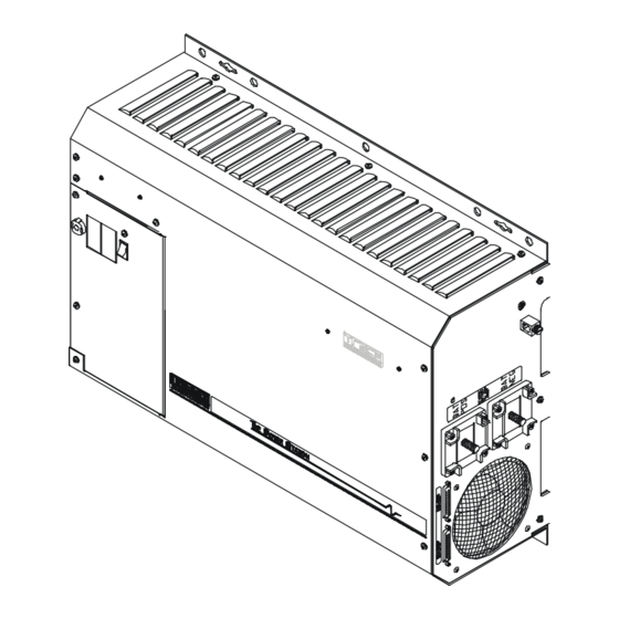
Page 120: Dimensions
= 15.25” (38.7 cm) total 21“ + 1.5” (for DC terminals) = 22.5” (57.1 cm) total 6.5” (16.5 cm) Figure 36, PS Series Dimensions Copyright © Trace Engineering Company, Inc. Page Telephone: 360/435-8826 PS Series Inverter/Charger Fax: 360/435-2229 Part No. 3597 5916 - 195th Street N.E. -
Page 121: Figure 37, Ps Series Bottom Plate Mounting Dimensions
TECHNICAL INFORMATION Figure 37, PS Series Bottom Plate Mounting Dimensions Figure 38, PS Series – Showing Knockout Sizes for AC Wiring Copyright © Trace Engineering Company, Inc. Page Telephone: 360/435-8826 PS Series Inverter/Charger Fax: 360/435-2229 Part No. 3597 5916 - 195th Street N.E. -
Page 122: Installation Diagrams
The following diagrams and information is provided to assist you or your system installer with the design and installation of the Trace PS Series Inverter/Charger. Due to the variety of applications, models available, and differences in local and national electrical codes, these diagrams and information should be used as general guidelines only. -
Page 123: Figure 40, Ps Series Installation Schematic
TECHNICAL INFORMATION Figure 40, PS Series Installation Schematic Copyright © Trace Engineering Company, Inc. Page Telephone: 360/435-8826 PS Series Inverter/Charger Fax: 360/435-2229 Part No. 3597 5916 - 195th Street N.E. Arlington, WA 98223 www.traceengineering.com Rev. D: November 23, 1999... -
Page 124: User Settings Worksheet
USER SETTINGS WORKSHEET USER MENU (all models) Your PS Series Inverter/Charger may have USER and/or SETUP operating settings that are different or are changed from the standard factory settings. Use the following Record Sheets to record your specific USER and SETUP operating settings for:... - Page 125 18 Set Start Charge time h:m 00:00 – 23:50 21:00 Set End Charge time h:m 00:00 – 23:50 21:00 Copyright © Trace Engineering Company, Inc. Page Telephone: 360/435-8826 PS Series Inverter/Charger Fax: 360/435-2229 Part No. 3597 5916 - 195th Street N.E.
- Page 126 18 Set Start Charge time h:m 00:00 – 23:50 21:00 Set End Charge time h:m 00:00 – 23:50 21:00 Copyright © Trace Engineering Company, Inc. Page Telephone: 360/435-8826 PS Series Inverter/Charger Fax: 360/435-2229 Part No. 3597 5916 - 195th Street N.E.
- Page 127 18 Set Start Charge time h:m 00:00 – 23:50 21:00 Set End Charge time h:m 00:00 – 23:50 21:00 Copyright © Trace Engineering Company, Inc. Page Telephone: 360/435-8826 PS Series Inverter/Charger Fax: 360/435-2229 Part No. 3597 5916 - 195th Street N.E.
- Page 128 18 Set Start Charge time h:m 00:00 – 23:50 21:00 Set End Charge time h:m 00:00 – 23:50 21:00 Copyright © Trace Engineering Company, Inc. Page Telephone: 360/435-8826 PS Series Inverter/Charger Fax: 360/435-2229 Part No. 3597 5916 - 195th Street N.E.
-
Page 129: Appendix
APPENDIX APPENDIX OPTIONS Options available for the PS Series Inverter/Charger include a choice of remote controls, a conduit box and relay modules. You may connect either the SWRC or SWCA, but they cannot be connected at the same time. SWRC The optional SWRC remote control (Trace part number SWRC or SWRC/50FT) has the ability to communicate and adjust settings in the PS Series inverter. - Page 130 The optional RC8 remote control provides an LED status of the inverter and duplicates the Power On/Off Switch on the PS Series Inverter/Charger. It connects directly to the port labeled RC8 on the AC board located under the top cover access panel (see page 13 for the location).
-
Page 131: Other Products
Engineering inverter line. OVERCURRENT PROTECTION – FUSES AND DISCONNECTS The Trace Engineering fuseblock (TFB) protects your battery, inverter, and high amperage cables from damage by short circuits and overloads. Simply select the proper size fuseblock and install between the inverter and battery in the ungrounded conductor (typically the positive cable). -
Page 132: Reference Tables & Graphs
000 (3/0) 10.40 85.0 0.0766 0000 (4/0) 11.68 107.2 0.0608 Page Copyright © Trace Engineering Company, Inc. Telephone: 360/435-8826 PS Series Inverter/Charger 5916 - 195th Street N.E. Fax: 360/435-2229 Part No. 3597 www.traceengineering.com Rev. D: November 23, 1999 Arlington, WA 98223... -
Page 133: Figure 41, Awg Wire Size
43 – 57 (SELL mode = 49 – 51) 43 – 57 Delay Period (seconds) 20 (SELL mode = 90) Page Copyright © Trace Engineering Company, Inc. Telephone: 360/435-8826 PS Series Inverter/Charger 5916 - 195th Street N.E. Fax: 360/435-2229 Part No. 3597 www.traceengineering.com... -
Page 134: Table 15, Battery Charger Default Settings
200 Amp #6 AWG 300 Amp #4 AWG 400 Amp #3 AWG Page Copyright © Trace Engineering Company, Inc. Telephone: 360/435-8826 PS Series Inverter/Charger 5916 - 195th Street N.E. Fax: 360/435-2229 Part No. 3597 www.traceengineering.com Rev. D: November 23, 1999... -
Page 135: Warranty/Repair Information
All remedies and the measure of damages are limited to the above. Trace Engineering shall in no event be liable for consequential, incidental, contingent, or special damages, even if Trace Engineering has been advised of the possibility of such damages. -
Page 136: Warranty Or Repair Service Required
Trace Engineering factory, unauthorized service performed on any Trace product will void the existing warranty. You must notify Trace Engineering, before returning any equipment for repair, to obtain a RMA (Return Merchandise Authorization number, please contact our Warranty Coordinator at:... -
Page 137: Index
Set Max Cranking Seconds, Menu (13)......50 Battery Selling, Menu (17)..........52 Set Max Sell Amps AC, Menu (17).........52 Battery Sizing..............97 Set Maximum Run Time, Menu (12).......49 Copyright © Trace Engineering Company, Inc. Page Telephone: 360/435-8826 PS Series Inverter/Charger Fax: 360/435-2229 Part No. 3597 5916 - 195th Street N.E. - Page 138 Gen Auto Start Setup, Menu (12)........48 Menu (18) - Grid Usage Timer........53 Gen failed to start, Menu ( 2)........37, 41 Menu (19) - Information File Battery.......53 Page Copyright © Trace Engineering Company, Inc. Telephone: 360/435-8826 PS Series Inverter/Charger Fax: 360/435-2229 Part No. 3597 5916 - 195th Street N.E.
- Page 139 Load Amp Start Ready ...........38 Input Upper Limit VAC..........37, 41 Set Generator..............36 Installation Diagrams ............120 Voltage Start Ready ............38 Installation Guidelines Menu ( 3) - Trace Engineering AC Wiring ...............20 Information Display ............38 Introduction................5 Press Reset Now For Defaults ........38 Inverter Menu ( 4) - Meters Controls and Indicators ............9...
- Page 140 Set Input Upper Limit VAC, Menu (11) .......48 Overtemp................11 Set Inverter, Menu ( 1) ............36 Set LBCO Delay, Menu ( 9)..........46 Page Copyright © Trace Engineering Company, Inc. Telephone: 360/435-8826 PS Series Inverter/Charger Fax: 360/435-2229 Part No. 3597 5916 - 195th Street N.E.
- Page 141 DC Wiring ...............21 Over Current ..............42 DC Disconnect............22 Transformer overtemp ..........42 DC Overcurrent Protection .........22 GEN Menu Button............34 Copyright © Trace Engineering Company, Inc. Page Telephone: 360/435-8826 PS Series Inverter/Charger Fax: 360/435-2229 Part No. 3597 5916 - 195th Street N.E.
-
Page 144: 5916 - 195Th Street N.e
5916 - 195th Street N.E., Arlington, WA 98223 Phone: (360) 435-8826 Fax: (360) 435-2229 visit our website at: www.traceengineering.com...
Need help?
Do you have a question about the PS Series and is the answer not in the manual?
Questions and answers