Table of Contents
Advertisement
Advertisement
Table of Contents

Related Manuals for Super Circuits DVQ19


Summary of Contents for Super Circuits DVQ19
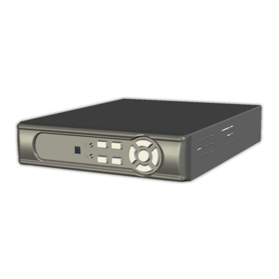
- Page 1 ○ 4CH MJPEG DVR U S E R M A N U A L VER.:1.0, CD...
-
Page 2: Table Of Contents
Contents 1. SAFETY PRECAUTIONS.................. 2 2. INTRODUCTION....................3 2.1 Product Introduction................3 2.2 Application ....................3 3. FEATURES ......................4 4. PACKING LIST ....................5 5. NAME and FUNCTION of EACH PART ..............6 5.1 Front Panel....................6 5.2 Rear Panel....................7 6. -
Page 3: Safety Precautions
1. SAFETY PRECAUTIONS CAUTION RISK OF ELECTRIC SHOCK. DO NOT OPEN! CAUTION : TO REDUCE THE RISK OF ELECTRICAL SHOCK, DO NOT OPEN COVERS (OR BACK). NO USER SERVICEABLE PARTS INSIDE. REFER SERVICING TO QUALIFIED SERVICE PERSONNEL. It is advised to read the Safety Precaution Guide through carefully before operating the product, to prevent any possible danger. -
Page 4: Introduction
2. INTRODUCTION 2.1 Product Introduction The product is perfect for office safety, personnel home security, public environments, industry surveillance, school, and so on. Quick and simple installation is the best choice for your own ultimate protection. The sate-of-art 4-channel M-JPEG digital video recording that replaces the old conventional video recorders and supports Chinese user interface. -
Page 5: Features
3. FEATURES Video system auto detection Auto detects video input (NTSC/ PAL) and supports combine use of color and b/w cameras. Supports high quality digital video recording Adopts M-JPEG compression technology (NTSC: 60 IPS/ PAL: 50 IPS). Video Size Video Resolution •... -
Page 6: Packing List
4. PACKING LIST Check to make sure all of the items shown below are included in your product package. If something is missing, contact your dealer as soon as possible. Item Description Item Picture DC 12V/ 2.5A Power Adapter Input: AC 100~240V Output: DC 12V/ 2.5A Power Cord CD-ROM... -
Page 7: Name And Function Of Each Part
5. NAME and FUNCTION of EACH PART 5.1 Front Panel : Record LED indicator. : Rewind button. : Fast forward button/ Enter Selection. : Left direction button / CH 2 screen display : Up direction button / CH 1 screen display : Right direction button / CH 4 screen display : Enter / Exit Menu : Down direction button / CH 3 screen display... -
Page 8: Rear Panel
5.2 Rear Panel (1) DC 12V [Power Input terminal]: power socket. (2) Video Input [VIDEO IN]: Connect to cameras. (3) Video Output [VIDEO OUT]: Connect to the monitor. (4) Audio Input [AUDIO IN] : RCA input port for an audio signal (5)... -
Page 9: Installation
6. INSTALLATION 6.1 System Configuration Please setup the connection by following the illustration shown below: Connect camera, monitor and power to enter monitoring mode. To backup images, connect the USB storage device. The DVR also supports VGA video output. -
Page 10: Hard Disk Installation
6.2 Hard Disk Installation Step 1: Remove the 3 screws from DVR as cycled below (PIC 1). (PIC 1) Step 2: Remove the front cover from DVR as indicated by the arrow (PIC 2). (PIC 2) - Page 11 Step 3: Place the HDD on the HDD plate and connect the power, SATA cable and the keyboard cable in place (PIC 3). NOTE! It’s very important to align the RED Stripe with Pin 1. Visually check to make sure all the pins are properly mated. (PIC 3) NOTE: Connect one end of the ribbon cable to the connector on the main board (A) and the other to a keyboard socket (B).
-
Page 12: Operating Procedure
7. OPERATING PROCEDURE 7.1 Power On After power on, DVR will auto-detect its peripherals (self-testing, auto detects the hard disk, and etc.). The system will detect the video input and judge whether the video system is NTSC or PAL. When video input is unable to be detected (VIDEO LOSS), the system will send out an alarm (it will not affect the actual recording, but when all (1CH-4CH) video images disappears, the DVR will stop recording). -
Page 13: Record Mode
7.3 Record Mode Icon Description CH2 : Black screen indicates display and record function switched OFF. CH3 : Blue screen indicates video-loss. Symbol [M] indicates manual recording. Symbol [S] indicates schedule recording. When both manual and schedule recording has been enabled, manual recording will be the first priority to be displayed. -
Page 14: Playback Mode
7.4 Playback Mode Press Play《 》button to enter “Time Search” display. Press Fast Forward《 》button to enter Time Setup mode. After time setup has been completed, press《 MENU 》button to return to Time Search display and press Play 《 》 button again to playback the selected time. -
Page 15: System Setup
8. SYSTEM SETUP 8.1 Menu Setup (1) MAIN MENU: Item subject (First menu layer does not have a subject). (2) Menu Layer Indication: The device consists of four menu layers. ■ :First Menu Layer (Main Menu) ■■ :Second Menu Layer ■■■... - Page 16 (3) Menu Operation and Setup Press《▲》 or《▼》button to move the cursor. Press《 》or《 》button enter the sub menu. Press《 MENU 》button. Under second or third menu layer, the system will return to the previous menu layer (second layer to first layer or third layer to second layer) and auto updates the modified data.
-
Page 17: Camera Setup
■■ 8.2 Camera Setup 1. Press《▲》and《▼》button to move up and down the menu item. 2. Press《 》or《 》button to make changes. 3. Press《MENU 》button to exit “Camera Setup” menu. 4. [Camera Setup] is situated on the second menu layer. Under this selection user may setup the following function: Channel, Display &... -
Page 18: Record Setup
8.3 Record Setup ■■ 1. Press《▲》and《▼》button to move up and down the menu item. 2. Press《 》or《 》button to make changes or to enter a next menu layer. 3. Press《MENU 》button to exit “Record Setup” menu. 4. [Record Setup] is situated on the second menu layer. Under this selection user may setup the following function: Record Frame, Record Quality, Event Record Duration, and Record Schedule. -
Page 19: Record Frame
8.3.1 Record Frame ■■■ 1. Press《▲》and《▼》button to move up and down the menu item. 2. Press《 》,《 》or《 》button to make changes. 3. Press《MENU 》button to exit “Record Schedule Setup” selection. Maximum frames for all 4 channels are 60 (NTSC)/ 50 (PAL) frames. Note: Recording frames for each channel is (0 frames) or 3 ~ 30 frames. -
Page 20: Record Schedule
8.3.2 Record Schedule ■■■ 1. Press《▲》and《▼》button to move up and down the menu item. 2. Press《 》button to make changes. 》or《 3. Press《MENU 》button to exit “Record Schedule Setup” selection. Color Bar Description Grey ] Indicates no record will be made for this time period. Orange ] Indicates recording is made for this time period. -
Page 21: Motion Detection Setup
8.4 Motion Detection Setup ■■ 1. Press《▲》and《▼》button to move up and down the menu item. 2. Press《 》or《 》button to make changes or to enter a next menu layer. 3. Press《MENU 》button to exit “Motion Detection” menu. 4. [Motion Detection Setup] is situated on the second menu layer. Under this selection user may setup the following function: Channel, Sensitivity and Motion Area. -
Page 22: Motion Area
8.4.1 Motion Area ■■■ 1. Press《▲》and《▼》button to move up and down the menu item. 2. Press《 》button to setup the starting point of the motion area. 3. Press《▲》and《▼》to select the range of motion detection area. 4. Press《 》button to setup the ending point of the motion area. 5. -
Page 23: Screen Setup
8.5 Screen Setup ■■ 1. Press《▲》and《▼》button to move up and down the menu item. 2. Press 《 》 or 《 》 button to make changes or to enter a next menu layer. 3. Press《MENU 》button to exit “Screen Setup” menu. 4. -
Page 24: Video Adjustment
8.5.1 Video Adjustment ■■■ 1. Press《▲》, 《▼》, 《 》or《 》button to adjust the screen. 2. Press《MENU 》button to exit “Video Adjustment” selection. -
Page 25: Audio Setup
8.6 Audio Setup ■■ 1. Press《▲》and《▼》button to move up and down the menu item. 2. Press《 》or《 》button to make changes 3. Press《MENU 》button to exit “Audio Setup” menu. 4. [Audio] is situated on the second menu layer. Under this menu user may setup the following function: Record, Mute, Input Volume and Output Volume. -
Page 26: System Setup
8.7 System Setup ■■ 1. Press《▲》and《▼》button to move up and down the menu item. 2. Press《 》or《 》button to make changes or to enter a next menu layer. 3. Press《MENU 》button to exit “System Setup” menu. 4. [System Setup] is situated on the second menu layer. Under this menu user may setup the following function: Hard Disk Setup, Password Setup, Time Set, Event List, Loss Alarm, Motion Alarm, Alarm Duration and F/W Upgrade. -
Page 27: Hard Disk
8.7.1 Hard Disk ■■■ 1. Press《▲》and《▼》button to move up and down the menu item. 2. Press 《 》 and 《 》 button to make changes or to enter a next menu layer. 3. Press《MENU 》button to exit “Hard Disk” selection. 4. -
Page 29: Format Hdd
8.7.1.1 Format HDD ■■■■ 1. Press 《 ▲》 , 《▼》 , 《 》 or 《 》 button to move to the desired password number. 2. Press《 》button enter password(must be 6 digits). 3. After entering 6 digits password, use《▲》/《▼》/《 》/《 》button to move the cursor to “Enter”. - Page 30 Fig 1 Fig 2...
- Page 31 Fig 3...
-
Page 32: Password Setup
8.7.2 Password Setup ■■■ 1. Press《▲》and《▼》button to move up and down the menu item. 2. Press 《 》 or 《 》 button to make changes or to enter a next menu layer. 3. Press《MENU 》button to exit “Password” selection. 4. [Password Setup] is situated on the third menu layer. Under this selection user may setup the following function: Password Change, Menu Password and Record Password. -
Page 33: Password Change
8.7.2.1 Password Change ■■■■ 1. Press 《▲》 , 《▼》 , 《 》 or 《 》 button to move to the desired password number. 2. Press《 》button and enter password(must be 6 digits). 3. After entering 6 digits password, use《▲》/《▼》/《 》/《 》button to move the cursor to “Enter”. - Page 34 Fig 4 Fig 5...
- Page 35 Fig 6 Fig 7...
-
Page 36: Time Set
8.7.3 Time Set ■■■ 1. Press《▲》and《▼》button to move up and down the menu item. 2. Press《 》or《 》button to make changes or to enter change mode. 3. Press《MENU 》button to exit “Time Set” selection. 4. [Time Set] is situated on the third menu layer. Under this selection user may setup the following function: Time Zone, Time Set, Daylight Saving Time and Apply. -
Page 37: Event List
8.7.4 Event List ■■■ 1. Press《▲》and《▼》button to move to the desired event item or use《 》 and《 》button to move to the previous or next event list page. 2. Press《 》button to playback event. 3. Press《 》button to Fast Forward, press《 》button to Fast Rewind and press《... -
Page 38: Software Update
8.7.5 Software Update ■■■ Fig 8 Fig 9... - Page 39 1. When entering software update selection and the USB storage device has firmware image files stored, Fig 6 is shown and followed by Fig 7. 2. Press《 》button to update software. 3. During update process, Fig 8 is shown. Fig 10 4.
- Page 40 Fig 11 Fig 12...
- Page 41 Fig 13 Fig 14...
-
Page 42: Exit
8.8 Exit ■■ 1. Press《▲》and《▼》button to move up and down the menu item. 2. Press《 》button to confirm. 3. [Exit] is situated on the second menu layer. Under this selection user may setup the following function: Exit & Save Changes, Exit & Discard Changes and Load Setup Default. -
Page 43: Backup Via Usb Memory Stick
8.9 Backup via USB Memory Stick In order to save the video data with USB memory stick, you should first stop record and enter playback mode, as shown below (Fig 13). 2. Press《MENU 》button to setup the start and end time period of recorded video data that you want to save on the USB memory stick. - Page 44 Fig16 Fig 17...
- Page 45 Fig 18...
-
Page 46: Remote Control (Option)
9. REMOTE CONTROL (option) Remote Control ID Button Name Description ○ ○ CHECK ID Remote Control ID ○ ○ Rewind ○ ○ Fast Forward/ Enter Selection ○ ○ ○ ○ ○ MENU Enter / Exit Menu ○ ○ Up direction button / CH 1 screen display ○... -
Page 47: Hdd Player Software Description
10. HDD Player Software Description System Requirement OS (Operating System) Windows XP. Hardware Requirement 2.8GHz or higher. ※ 1GMByte or higher. ※ 1. Installation Software Installation 1. During installation, you will need a desktop or laptop computer that meets these minimum requirements: Windows XP. -
Page 48: User Interface
User Interface Viewer/ Player Connection Status Function Button Viewer Function Button Description Press this button to enter player Press this button to enter DVR Viewer window. connection window. Press this button to enter DVR Press this button to disconnect from login window. - Page 49 2.1 DVR Connection (Applicable only to Network DVR) After pressing the connection button, a Login window appears. Please enter DVR IP address, remote-site Password, and Port to enter DVR connection window.
- Page 50 After entering DVR LIVE display, use panel button for operation control. Connection Status DVR Player Operation Button Screen Switching Button Connection Status: Display current connection status (figure shown above), system indicates either connected or disconnected. When the Viewer network disconnects, Viewer tries to automatically re-connect.
-
Page 51: Function Button
2.2 DVR Setup (Applicable only to Network DVR) Press [MENU] button to activate DVR setup menu and precede DVR function setup. Function Button CH1 (similar to DVR-site button application)/ UP (similar to menu button application). CH3 (similar to DVR-site button application)/ DOWN (similar to menu button application). CH2 (similar to DVR-site button application)/ LEFT (similar to menu button application). - Page 52 2.3. Viewer Setup (Applicable only to Network DVR) Right click on the Viewer window, viewer drop down menu appears (corresponding configuration setup can be done). Player: Switch to Player window. NetViewer: Switch to NetViewer remote connection window. Disconnect/ Connect: Select “Disconnect” option under connection status or “Connect”...
- Page 53 Viewer Network Options Setup Always On Top: Setup window display to always be on top. Use DirectDraw: Enable DirectDraw to accelerate image processing functions (Your operating system and graphic hardware must support DirectDraw). Path for local recording: Save LIVE video to the PC HDD directory.
- Page 54 3. Player Guide After the software installation has been completed, open-up Vx4CViewer. Move the cursor to [Player] and then left click to enter Player user operating interface, as show below: Player Status Function Button Player Panel Description Press this button to enter player Press this button to enter DVR Viewer window.
- Page 55 Press [Open] button to open-up file, a folder appears and you may select a file from the folder to playback.
- Page 56 3.2 Player Control Player Main Display Channel Display Playback Status Snapshot and Channel Switching Button Playback Control Button Chanel Display: Show channel name of the current playback file. Use right-click menu to Enable/ Disable the function. Playback Status: Current playback speed and related time information. Playback Control Button: Control buttons to proceed file Playback, Pause and Fast Forward.
- Page 57 3.3. Player Setup Right click on the Player window, player drop down menu appears (corresponding configuration setup can be done). Player: Switch to Player window. NetViewer: Switch to NetViewer remote connection window. Open File: Open-up a file. Open Disk: Open-up a disk. Export: Save the file as AVI format (this function is only effective when playback is faused).
- Page 58 Capture: Use this function to capture a certain part of the file and save it into a separate file. Application method: First move to the stating point that you wish to retrieve. In the player drop down menu, click item “Capture Mark In”...
- Page 59 Player Options Setup Always on top: Setup window display to always be on top. Use DirectDraw: Enable DirectDraw to accelerate image processing functions (Your operating system and graphic hardware must support DirectDraw). Show channel title: Display channel title setup. Repeat playback: Repeat playback function setup. On screen display date/time format: To change the time display format.
-
Page 60: Troubleshooting
11. TROUBLESHOOTING Question Answer 1 What brands of hard drives can I use? WD, Seagate, and Hitachi. Which storage capacity of a USB 8G and below. storage device is suggested? -
Page 61: Specification
12. SPECIFICATION Format NTSC / EIA or PAL / CCIR Compression MJPEG Video Input 4 CH, BNC Output 1 CH BNC Resolution 720x480 (NTSC), 720x576 (PAL) Display Frame Rate Max. 120 / 100 IPS (NTSC / PAL) Division Single, Quad Resolution 640x224 (NTSC), 640x272 (PAL) Frame Rate... - Page 62 MEMO...
Need help?
Do you have a question about the DVQ19 and is the answer not in the manual?
Questions and answers