Table of Contents
Advertisement
Quick Links
Advertisement
Table of Contents

Related Manuals for Super Circuits DVQ-2


Summary of Contents for Super Circuits DVQ-2
- Page 1 DVQ-2, DMR 4/8/16 RT USER MANUAL...
- Page 2 SUPER/CIRCUITS 11000 NORTH MOPAC EXPRESSWAY SUITE 300 Austin, TX 78759 Phone 800-335-9777 • Fax 866-2567-9777...
-
Page 3: Warning
Please read instructions thoroughly before operation and retain it for future reference. he lightning fl ash with arrowhead symbol, within an equilateral triangle, is intended to alert the user to the presence of uninsulated “dangerous voltage” within the product’s enclosure that may be of suffi cient magnitude to constitute a risk of electric shock to persons. -
Page 4: Table Of Contents
TABLE OF CONTENTS Warning..............................3 1. OVERVIEW ............................6 1.1 General Information ........................6 1.2 Features............................6 1.3 Package Contents........................7 2. FRONT AND REAR PANELS ......................8 2.1 Front Panels..........................8 2.2 Rear Panels ..........................12 3. INSTALLATION GUIDE ......................... 15 3.1 Camera and Monitor Installation....................15 3.2 System Confi guration .........................17 4. - Page 5 7.0 NETWORKING..........................45 7.1 Things to do before networking your DVR................45 7.2 Test your connection........................48 7.3 Software Installation.........................50 7.4 Installation..........................50 7.5 Remote Video Server Login Panel...................51 7.6 Control Panel...........................52 7.7 System Confi g..........................54 7.8 Network............................54 7.9 DVR............................56 7.10 Detection..........................56 7.11 Network Backup (Cool Feature).....................57 7.12 Video Backup Player......................58 7.13 Search List..........................59 7.14 Timer Record..........................60...
-
Page 6: Overview
1. OVERVIEW 1.1 General Information • Video Compression Frame: MJPEG ; • Format CIF: MPEG4 • USB Interface • Backup Device Network remote backup • IR Transmitter • Audio I/O 1 audio input, 1 audio output (Mono) • R.E.T.R. (Remote EventTrigger Recording) •... -
Page 7: Package Contents
1.3 Package Contents • DVQ unit × 1 • Power Supply × 1 • Power Cable × 1 • Manual × 1 • Software CD-R × 1 DMR 4, 8, 16 RT DVQ-2 Power cord Manual Power supply Software... -
Page 8: Front And Rear Panels
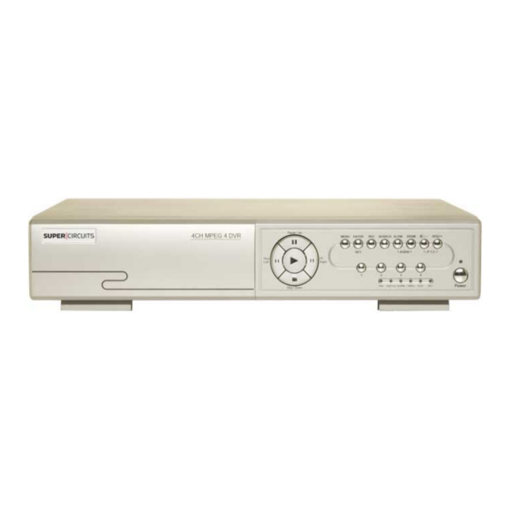
2. FRONT AND REAR PANELS 2.1 Front Panels DVQ-2 DMR 4, 8, 16 RT Left, Right keys Search Power Menu Enter key Plus +, Minus - keys Up, Down keys... - Page 9 1) LED Indicators The following LEDs will be on when: • HDD (Hard Drive): HDD is reading or recording • HDD Full: HDD is full. • ALARM: Alarm is triggered • TIMER: When timer recording is turned on • PLAY: Under playing status •...
- Page 10 Press “ ” button to display the 4 channels. Press “-” button to change the setting in the menu. Press “SEQ” button to activate the call monitor, and press again to quit. Press ”+” button to change the setting in the menu. or POWER Press POWER button for 1 to 3 seconds to turn the DVR on or off.
- Page 11 2.1.2 Playback Press “ ” or “PLAY” button on the front panel, and the device will display the last recorded video. Note: For playback to work properly the DVR needs to record a minimum of 8192 video frames. Playback related operations are described below: •...
-
Page 12: Rear Panels
2.2 DVQ-2 Rear Panel 1) 75 / HI-IMPEDANCE When using LOOP, switch to HI-IMPEDANCE. When not using LOOP switch to 75 . 2) LOOP / INPUT (For channel 1~4) LOOP Video output connector. INPUT: Connect to video sources. Note: For video and audio applications, use inputs 1 or 2 with a audio camera. - Page 13 2.2 DMR 4, 8, 16 RT Rear Panel...
- Page 14 2.2 DMR 4, 8, 16 RT Rear Panel 1) DISK ARRAY PORT: Connect to one disk array for extending HDD capacity. 2) IR PORT: Connect to the IR receiver. 3) RS485 PORT: Connect to external devices (such as PTZ camera) with RS485-A and RS485-B. 4) EXTERNAL I/O PORT: Insert the supplied 15PIN DSUB to this port for connecting external devices (alarm input, external alarm, PTZ camera).
-
Page 15: Installation Guide
3.0 Installation Guide 3.1 Camera and Monitor Installation This manual has been carefully written to help you assemble and confi gure your digital video recorder system for optimal performance. It’s easy to setup your digital video recorder just follow the instructions on the following pages. If you have any comments questions about this manual, please feel free to call us at 800-335-9777. - Page 16 4. Test each component of your video system prior to installation. Connect each camera directly to the video monitor, using a new power adapter and cable for each camera. This will test each component of your video system prior to installation.
-
Page 17: System Confi Guration
DVR and Monitor Installation 3.2 DVQ-2 SYSTEM CONFIGURATION... - Page 18 3.2 DMR 4, 8, 16 RT SYSTEM CONFIGURATION...
-
Page 19: Getting Started
4.0 GETTING STARTED 4.1 INTRODUCTION This digital video recorder is designed to function right out of the box. We made setting up your DVR easier by adjusting the time, date and record settings for you. Your DVR is set to record for 14 days with the video quality and frame rate set to the highest settings. -
Page 20: Reconfigure Your Dvr
1. Press the MENU key on the front panel to login. The Menu allows you to confi gure your digital video recorder (DVR) settings. 2. Use CH. SELECTORS 1 ~ 16 to key in the password. DVQ-2 DMR 4, 8, 16 RT Left, Right keys... - Page 21 The password screen will appear: NOTE: The default Password is 0000. Simply press the Enter button. To key-in the Password, press the “RIGHT” and “LEFT” buttons to move between numbers, and use the “- MINUS” and “+ PLUS” buttons to change values. KEY UNLOCK PASSWORD 0000 Press the >ENTER button once and the MENU screen will appear.
-
Page 22: Reset To Factory Default
4.3 RESET DEFAULT Select ADVANCE> SYSTEM> RESET and press the ENTER button. NOTE: (> = hit the ENTER KEY) Reset all system settings to factory default settings. ADVANCE SYSTEM MENU CAMERA SERIAL TYPE RS-485 RECORD DETECTION BAUD RATE 02400 TIMER ALERT HOST ID DATE... -
Page 23: Date/ Time
Push the LEFT key to select YES and push the ENTER key and confi rm by pushing the ENTER key again to select OK. CLEAR HDD CLEAR HDD CLEAR HDD CLEAR OK ? ARE YOU SURE ? YES NO Set the DVR time and date. 4.5 DATE/ TIME 8. -
Page 24: Motion Detection
4.7 MOTION DETECTION From main MENU select ADVANCE> DETECTION> DETECTION SETUP and press the ENTER key. Select DETECTION, press ENTER key. NOTE: (> = hit the ENTER KEY) MENU ADVANCE DETECTION RECORD CAMERA DETECTION SETUP TIMER DETECTION DETECTION TIMER DATE ALERT ADVANCE REMOTE... -
Page 25: Record Quality And Ips (Images Per Second)
TIMER RECORD ENABLE DATE OVERWRITE ADVANCE RECORD IMG SIZE FRAME RECORD QUALITY BASIC MANUAL RECORD IPS EVENT RECORD IPS TIMER RECORD IPS TOTAL IPS SHARE Use Table 1 to set your RECORD QUALITY and IPS for DVQ-2. DVQ-2 TABLE 1... - Page 26 Use Table 2 to set your RECORD QUALITY and IPS for DMR 4, 8, 16 RT. DMR-16RT Table 2 1) Recording time varies depending on: * Different camera quality * Different picture composition (object movement) 2) For DMR-8RT Record day: multiply “Record day” by 2. For DMR-4RT Record day: multiply “Record day”...
- Page 27 Use example below to understand how to setup your IPS and QUALITY settings. EXAMPLE: Setup a DVR to record for 14 days using the FRAME RECORD MODE. Go to table 1 and you will see 10 options to choose from. If your preference is video quality, your best option is 21.3 days with a QUALITY of BEST and an IPS of 7.
-
Page 28: Menu Configuration
5.0 MENU CONFIGURATION 5.1 MENU INTRODUCTION DVQ-2 DMR 4, 8, 16 RT Left, Right keys Search Power Menu Enter key Plus +, Minus - keys Up, Down keys Press the MENU button and enter your password. NOTE: If you get an error message “Password Error”, you have entered an incorrect password. -
Page 29: Record
KEY UNLOCK PASSWORD 0000 The default admin password is 0000. Enter the default password, and press “ENTER”. MAIN MENU MENU There are 4 options available in the Main Menu: RECORD -------- Record Setup RECORD TIMER ----------- Scheduling Record TIMER DATE ------------ Date Setup DATE ADVANCE-------System Confi... -
Page 30: Timer
1) MANUAL RECORD ENABLE Start / stop the manual recording. 2) EVENT RECORD ENABLE Start / stop the event recording. When enabled the recording is triggered by motion or external alarm. 3) TIMER RECORD ENABLE Start / stop the schedule recording. 4) OVERWRITE Select to overwrite previous recorded data for automatic continuous recording. -
Page 31: Date
1) DATE Schedule up to 7 recording days: SUN / MON / TUE / WED / THU / FRI /SAT / MON–FRI / SAT-SUN / DAILY / OFF. Please see example below to schedule midnight applications. Example 1: To schedule from Sunday 23:30 to Monday 23:30, set Sunday from 23:30 to 23:30. Example 2: To schedule from Sunday 08:00 to Monday 15:00, set Sunday from 08:00 to 24:00, and Monday 24:00 to 15:00. -
Page 32: Camera
5.6 Camera Advanced camera settings, change camera title, or adjust the brightness. Select “CAMERA”, and press ”ENTER”. ADVANCE CAMERA CAMERA TITLE BRIG CONT SATU HUE COV REC DETECTION DISPLAY ALERT REMOTE SYSTEM NETWORK BACKUP HDD INFO EVENT LOG 1) TITLE Change the default camera name. - Page 33 3. Advance motion detection settings. Use AREA to setup motion detection for a selected viewing area. Cameras will pickup areas of movement like moving tree branches in the back ground and trigger false motion alarm recordings. The AREA SETUP feature can be used to block out the tree branches, thereby reducing false motion alarms. Anything around the tree that is moving will trigger the motion detection alarm and start recording.
- Page 34 You can also up set up multi-detection areas. Press MINUS to set the entire area under motion detection. Press to disable motion detection for the entire area. 4) LS (Level of Sensitivity) Use to set motion detection sensitivity. The smaller the value, the higher sensitivity for motion detection. The highest sensitivity setting is 00, and the lowest sensitivity setting is 15.
-
Page 35: Detection Timer
NOTE: When using an LCD monitor, and the “MONITOR OUT” setting in the “DISPLAY” menu DISPLAY ADVANCE is set to “MAIN”, the motion detection area setting will be disabled. TITLE DISPLAY CAMERA DATE DISPLAY DETECTION HDD INFO DISPLAY LOSS SCREEN BLUE ALERT PLAYBACK INFO... -
Page 36: Alert
4) LOSS SCREEN Set the video loss screen color (BLUE / BLACK). 5) PLAYBACK INFO Position playback information: CENTER or NORMAL 6) DWELL DURATION (SEC) Set CALL MONITOR duration time for each channel. (2 / 4 / 8 / 16 seconds) . 7) DE-INTERLACE DE-INTERLACE ON/ OFF. -
Page 37: Remote
3) KEY BUZZER Enable or disable sound when pressing buttons on front panel (ON / OFF). 4) VLOSS BUZZER Enable or disable sound for video loss (ON / OFF). 5) MOTION BUZZER Enable or disable sound when motion alarm is triggered (ON / OFF). 6) ALARM BUZZER Enable or disable sound when internal alarm is triggered (ON / OFF). -
Page 38: System
5.11 System Select “SYSTEM”, and press ”ENTER”. 1) SERIAL TYPE Press “ENTER” or “+” / “-” button to set ADVANCE SYSTEM the serial type (RS-485 / RS-232). CAMERA SERIAL TYPE RS-485 2) BAUD RATE DETECTION BAUD RATE 02400 Press “ENTER” or “+” / “-”button to set DISPLAY the baud rate (2400 / 9600 / 19200 HOST ID... -
Page 39: Network
5.12 Network See Network Section in this manual, page 45. 5.13 Backup The backup fi le can be played in a PC using the supplied licensed Video Server software. Other media players like Windows Media Player or RealPlayer. can be used after the fi le is converted to an “AVI” format. See Video Backup Player page 42. -
Page 40: Hdd Info
• AVAILABLE SIZE Display USB fl ash drive capacity. • CHANNEL • Select channel by pressing the “ENTER” button and use the symbols X or to select or deselect channels for backup. “X” channel is not selected for backup. • “... -
Page 41: Search
3) SYSTEM LOG Show system error codes. Reference error code list below: Error Code in “SYSTEM LOG”: Description: 1) SYS ERR 01-YYY #defi ne SYS_ERR_AV087_ERR 1) Compression error A.) YYY=000 Audio chip error B.) YYY=001- AV087 Chip for CH1-4 error 2) SYS ERR 02-XXX #defi... -
Page 42: Additional Operations
• Key Lock Off: Enter password to exit “Key Lock” mode. (Same password used for MENU entry) Note: See Password page 31. 6.2 Switch NTSC / PAL System (For DVQ-2 only) • Switch to NTSC System ( or POWER + Press “POWER”... -
Page 43: Upgrade
6.3 Upgrade (1) Firmware / Multilanguage OSD Upgrade • Use USB to upgrade: Format the USB memory to FAT 32. Get the upgrade fi les from your distributor. Save the upgrade fi les to your USB memory (do not change the fi le name). Go to “MAIN MENU” → “SYSTEM” → “UPGRADE”, and press the “ENTER” button. -
Page 44: Ptz Camera Setup And Control
In the PTZ control mode, press “+” button to zoom in, press “-” button to zoom out, and press “UP”, “DOWN”, “LEFT” or “RIGHT” buttons on the DVR front panel to adjust the PTZ angle. DVQ-2 RS485 DMR 4, 8, 16 RT... -
Page 45: Networking
2. To connect to the world wide area network for remote viewing you must confi gure your router to allow port forwarding. Super Circuits does not provide technical support for router setup. Contact your service provider/ router manufacturer for support on setting up port forwarding. Use port number 8000. - Page 46 2. Select “NETWORK”, and press ”ENTER”. ADVANCE NETWORK CAMERA NETWORK TYPE STATIC DETECTION 168. 95. 1. 1 DISPLAY PORT 0080 ALERT REMOTE SYSTEM NETWORK BACKUP HDD INFO EVENT LOG 3. NETWORK TYPE There are 3 network types: STATIC, PPPOE and DHCP. •...
- Page 47 • PPPOE PPPoE needs one “username” and “password” subscribed from ISP provider. NETWORK PPPOE NETWORK TYPE PPPOE 160 . 121 . 346 . 236 168. 95. 1. 1 GATEWAY 160 . 121 . 346 . 236 PORT 0080 NETMASK 255 . 255 . 255 . 254 •...
-
Page 48: Test Your Connection
2) Set the DVR network setting in “SYSTEM CONFIG” using Video Server → select “PPPOE” in “IP TYPE”. Type the “User Name” and “Password” given to you from your ISP. Press ”APPLY” button to confi rm the setting. 3) Set the DVR DDNS settings in the “SYSTEM CONFIG” → using Video Server: •... - Page 49 4. The Dos window will display “Reply from” the IP address 3 to 4 times. You will see “Packets sent = X, Received = X and Lost = X. This will tell you that, you’ve successfully connected to your DVR and we can proceed. Like FIG.2 below.
-
Page 50: Software Installation
7.3 Software Installation 7.4 Installation 1) Install the software: Place the included CD disk into the CD-ROM drive, and install the Video Server and JAVA programs on to your PC. During the software installation you will step through the dialog sequence below. In some installations JAVA might not install because the fi... -
Page 51: Remote Video Server Login Panel
2. After setup, you will see the Video Server S shortcut icon on the desktop. For the latest AP software updates, please check with your distributor. 7.5 Remote Video Server Login Panel 3. Double click “ “ (Video Server ) on your PC to enter the login page. Key in IP address (192.168.1.10), username (admin), password (admin) and port (8000) in the login page. -
Page 52: Control Panel
Remote Video Server LOGIN WINDOW Address Book Press Address Book button to add a new IP address into the IP address book, or choose any preset IP address to access the software AP software. Copy Press Copy button to copy all the software installation fi les, and keep all the settings of the video web server for next software installation on another PCs. - Page 53 h. System Confi g : Allows you to confi gure Network, DVR, Alarm and General settings. Very powerful tool for remote control of your DVR. Will discuss the System Confi g in more detail in this section. i. Number of Online Users j.
-
Page 54: System Confi G
7.7 System Confi g Allows you to remotely confi gure Network, DVR, Alarm and General settings. Double click on System Confi g 7.8 NETWORK: The network confi guration allows the DVR to connect to an LAN or Internet using Static IP, PPPoe or DHCP. Static IP is highly recommended because of the reliability. - Page 55 • PPPoE: PPPOE stands for Point-to-Point Protocol over Ethernet. Obtain ADSL service from ISP. Obtain and install PPPoE software. Choose “PPPOE” and enter the “User Name”, “Password” from your ISP (Internet Service Provider) and “Web Port”. Select “Network DDNS to set DDNS settings (see DDNS”...
-
Page 56: Dvr
7.9 DVR Camera channels can be adjusted independently. Select the desired camera channel and press “Edit” to enter. DVR: Selecting DVR will allow you to make changes to cameras, motion, create backup fi les, search fi le options, schedule recording and record settings. DEVICE: Remotely title or name your cameras. -
Page 57: Network Backup (Cool Feature)
Select AREA to setup motion area. a. DETECT (motion detection): Select motion detection function ON / OFF. b. AREA (motion detection area): Set the motion detection area by selecting the area grids with your mouse. Pink blocks represent the area that is not being detected while the transparent blocks are the area under detection. -
Page 58: Video Backup Player
After pressing “Start”, “Write CD Setting” pop-up window will display. Select “Close Disc” if your done burning. Select “Append Player” to install a video player software on the CD, allowing you to play the CD from any PC. Press “OK” to start CD backup, or press “CANCEL WRITING CD” to backup fi... -
Page 59: Search List
(5) Confi g. Setting Enter confi guration settings, and set fi le path, text color, and progress status text color. * Mute: Play the video without audio. * AV sync. : Play the audio and video synchronously. (6) Watermark is used prove the authenticity of the backup video. In the playback mode press this button to check authenticity of the BACKUP VIDEO. -
Page 60: Timer Record
Press Apply to create backup fi le Use Video Backup Player to view backup fi le 7.14 Timer Record Timer Record”, you can schedule up to 7 time events. • DATE Select a day from “DATE” dropdown menu. Options: OFF, SUN, MON, TUE, WED, THU, FRI, SAT, MON-FRI, SAT-SUN and DAILY. -
Page 61: Date
7.15 Date Set the date for your DVR. DO NOT change the date or time when the recording. • DATE Select the current date from “DATE” drop-down menu and enter the current time. • FORMAT Select the format for date display: Y-M-D, D-M-Y and M-D-Y. •... -
Page 62: Alarm
7.17 Alarm Enable of disable email or ftp and fi le back up alarm notifi cation. • Alarm Trigger Enable or Disable alarm trigger. • Alarm Method Select alarm notifi cation method when any alarm is triggered: Email or FTP. a) Email When an alarm is triggered an MJPEG email notifi... -
Page 63: Account
7.19 Account View the account information, set the maximum user number, and add / delete / edit user accounts. • Set the maximum number of users in Max User(s) setting. (1 ~ 5). • Create a new account by pressing “ADD”. To confi... -
Page 64: Operation Via Ie Browser
7.22 Operation via IE Browser You can view the images or operate your DVR using a IE (Internet Explorer) web browser. Note: Operating systems that support Video Web Server Browser are Windows 2000 and Windows XP. 1. Go to your Internet Explorer and type in your DVR IP address in the URL address box and press Enter. -
Page 65: Remote Ptz Camera Control Panel
Note: Down load lastest AP and Java 8.0 Remote PTZ Camera Control Panel a ~ i: Same as the DVR control panel a ~ i. J. Preset 1 ~ 16 Use Preset 1 ~ 16 positions to pre-defi ned camera views. k. -
Page 66: Faq/ Troubleshooting
9.0 FAQ/ TROUBLESHOOTING Please refer to the table below when troubleshooting. Problem Solution No power Check power cord connection. Make sure you have out let power. DVR is not responding when pressing keys. You might be under “Key Lock” mode. Press any key and enter the password to exit mode. -
Page 67: Default Value
9.1 Default Values Item Default Value ADMIN Password 0000 Detection GUEST Password 1111 Detection - LS Camera - BRIG Detection - SS Camera - CONT Detection - TS Camera - SATU Detection - RE Camera - HUE Detection - Alarm Camera - COV Network - IP Address 192.168.1.10 Camera - REC... -
Page 68: Appendix 2 Pin Configuration
Appendix 2 DVQ-2, DMR 4 RT Pin Confi guration EXTERNAL DEVICES Connecting External Alarms devices - example using a Siren: Use pins 7, 8 inputs and 15 COM when connecting external alarms like sirens, or horns. NO (Normally Open): Under standby mode the DVR COM pin 8 is disconnected with the normally open (NO) device. - Page 69 9 GND Signal GND 10 RS485-B DVR pin is used to serially communicate with remote PC using the RS-485 PROTOCOL. 11 RS485-A DVR pin is used to serially communicate with remote PC using the RS-485 PROTOCOL. 12 ~ 13 PIN OFF 14 ALARM RESET (PIN 14) and GND (PIN 9) are used to disable DVR alarm outputs and internal buzzer sounds.
- Page 70 Appendix 2 DMR 8, 16 RT Pin Confi guration PIN DESCRIPTION PIN NUMBERS: 1 GND Earth GND 2 ~ 9 ALARM INPUT Use ALARM INPUT ( PINS 2 -- 9 ) and GND ( PIN 1 ) to activate the DVR to start recording and trigger internal buzzer sound.
-
Page 71: Appendix 3 Rs-232 Protocol
Appendix 3, DVQ-2 & DMR 4, 8, 16 RT RS232 PROTOCOL Data: REMOTE PROTOCOL use 8 bit data, 1 start bit, 1 stop bit. -
Page 72: Appendix 4 Recording Time Table
Appendix 4, DVQ-2 RECORDING TIME TABLE... -
Page 73: Appendix 5 Compatible Usb Flash Drive Brand
fl ash drive by displaying the error message, “USB ERROR”. Note: Format the USB fl ash drive using “FAT 32” on your PC. DVQ-2, DMR 4, 8, 16 RT Compatible USB Flash Drives Appendix 6, DVQ-2 Compatible Hard Drives HDD. - Page 74 Appendix 6, DMR 4, 8, 16 RT Compatible Hard Drives HDD.
-
Page 75: Appendix 7 Menu Tree
Appendix 7, DVQ-2 & DMR 4, 8, 16 RT MENU TREE... - Page 76 Appendix 8 DMR 4, 8, 16 RT Specifi cations...
- Page 77 Appendix 8 DMR 4, 8, 16 RT Specifi cations...
-
Page 78: Appendix 8 Specifications
Appendix 11 DVQ-2 Specifi cations...
Need help?
Do you have a question about the DVQ-2 and is the answer not in the manual?
Questions and answers