Table of Contents
Advertisement
H.264 4/8/16-Channel Networkable DVRs
Installation and Setup Guide
Products: DMR90U, DMR91U, DMR92U
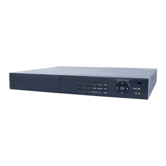
DMR90U 4-Channel DVR
DMR91U 8-Channel DVR and DMR92U 16-Channel DVR
PLEASE READ THIS MANUAL BEFORE USING YOUR SYSTEM, and always follow the
instructions for safety and proper use. Save this manual for future reference.
DMR9xU_RM
Advertisement
Table of Contents

Subscribe to Our Youtube Channel
Related Manuals for Super Circuits DMR90U


Summary of Contents for Super Circuits DMR90U
- Page 1 H.264 4/8/16-Channel Networkable DVRs Installation and Setup Guide Products: DMR90U, DMR91U, DMR92U DMR90U 4-Channel DVR DMR91U 8-Channel DVR and DMR92U 16-Channel DVR PLEASE READ THIS MANUAL BEFORE USING YOUR SYSTEM, and always follow the instructions for safety and proper use. Save this manual for future reference.
- Page 2 Operate this device only in environments where the temperature or humidity is within the recommended range. Operation at extreme temperatures or in very high or low humidity levels may cause electric shock and shorten the life of the CAUTION product.
-
Page 3: Table Of Contents
2.2.2 Controls and connectors (DMR90U) ........ - Page 4 TABLE OF CONTENTS SECTION 5 Accessing Your DVR With a Web Browser . . . . . . . . . . . . . . . . . . . . . . . . . . . . . . . . . . . . . . . . . . . . . . . 47 5.1 Connecting to your DVR with IE .
- Page 5 TABLE OF CONTENTS 7.4.2 Name ............... . .69 7.4.3 Position .
- Page 6 www.supercircuits.com...
-
Page 7: Systems Overview
1.1 About this document This document includes a simplified guide for setting up a basic system with a DMR90U, DMR91U, or DMR92U DVRs and standard analog cameras. Specific installation instructions for your cameras and other equipment you may add are usually included in the documentation provided with them. -
Page 8: Dvr Control
SECTION 1: SYSTEM OVERVIEW Remote Control 8-channel Audio RCA Mouse Cable Adapter Power Adapter DMR91U Your DMR91U DVR includes: DMR91U DVR unit • Remote Control • Mouse • Power adapter with cord for standard 120 VAC outlet. • 8-channel audio RCA cable adapter •... - Page 9 SECTION 1: SYSTEM OVERVIEW What you need The DVR is the central component of your security system. To install the DVR, you need: : PC compatible monitor • Uninterruptible power supply (UPS) (highly recommended). This device is used to ensure system stability during voltage •...
-
Page 10: Installing Your System
SECTION 2: INSTALLING YOUR SYSTEM SECTION 2 Installing Your System For each camera you received with your system, installation instructions are included. Follow the instructions to install all your cameras, then route the camera video and power extension cables to the location where the DVR will be setup. Some guidelines for camera placement, and considerations for weatherproof cameras and cable routing are provided below. -
Page 11: Dvr Installation
SECTION 2: INSTALLING YOUR SYSTEM The video and power extension cables have different connectors at each end - one end for the camera drop cable, and the other end for the DVR and power source. The photo below shows the typical connectors of the camera drop cable with the mating power and video connectors of the extension cable. -
Page 12: Controls And Connectors (Dmr90U)
SECTION 2: INSTALLING YOUR SYSTEM 2.2.2 Controls and connectors (DMR90U) DVR Front Panel Single/Multi Camera CH1 .. CH4 Infrared Display Toggle Camera Select Sensor Enter Menu Record Pan/Tilt/Zoom tqpu Menu Control Escape Backup Navigation Buttons Play/Pause Button Usage Toggles between single camera, multi-camera display. - Page 13 SECTION 2: INSTALLING YOUR SYSTEM DVR Backpanel IN1 - IN4 CH1 - CH4 Main Out Audio In Video In (VGA) Power Audio Out Main Out Alarm In/Out, Power DC 12V (BNC) RS422/RS485 Connections Connector Usage USB - MOUSE Use these USB ports to connect a mouse, or a backup device such as a flash drive or DVD recorder. AUDIO OUT Audio output from channel AUDIO IN channels 1, 2, 3, or 4.
-
Page 14: Controls And Connectors (Dmr91U, Dmr92U)
SECTION 2: INSTALLING YOUR SYSTEM 2.2.3 Controls and connectors (DMR91U, DMR92U) DMR91U, DMR92U Front Panel 0 .. 9, 10+ Buttons Infrared (Channel Select) Enter Sensor Power Off tqpu Status Menu Rewind Stop Fast Menu LEDs Record Navigation Buttons Forward Play/Pause Button Usage 1 . - Page 15 SECTION 2: INSTALLING YOUR SYSTEM DMR91U Back Panel (8 channel) CH1 - CH8 Main Out (VGA) Audio Power Fan Exhaust Video In Alarm In/Out, Power DC 12V Main Out (BNC) RS485 Terminals Connector Usage CH1 . . CH8 Video channel input connectors. RJ-45 connector for Ethernet LAN.
- Page 16 SECTION 2: INSTALLING YOUR SYSTEM DMR92U Back Panel (16 channel) VIN1 - VIN16 Spot Out (BNC) HDMI Audio In 1 - 8 Power Main Audio Out Main Out Alarm In/Out, Sensor Power Audio In 9 - 16 Main Out (BNC) RS-485 Terminals DC 12V Spot Audio Out...
-
Page 17: Connecting The System Together
SECTION 2: INSTALLING YOUR SYSTEM 2.3 Connecting the system together All connections to the DVR are made on the back of the unit. Camera Camera Drop Cable Microphone Monitor Video/Audio/Power Extension Cables Mouse VGA Cable To Audio Inputs To Alarm In/Out, PTZ Devices DVR Power Adapter Camera Power Source To UPS / 120 VAC Power... -
Page 18: Connect Alarm In, Alarm Out, Ptz Devices
Terminal block of DMR91U Terminal block of DMR92U DMR90U The DMR90U provides four alarm inputs (“1” .. “4”) with ground terminals (labeled “G”), and one alarm output (labeled “-” and “+”). RS422/RS485 terminations are labeled TX+, TX-, RX+, RX-. DMR91U The DMR91U provides four alarm inputs (“1”... -
Page 19: Install And Setup A Monitor
SECTION 2: INSTALLING YOUR SYSTEM 2.3.2 Install and setup a monitor 1. Install and setup your monitor in accordance with the instructions provided with the monitor. Do not power it on at this time. 2. Cable the DVR Monitor Out (VGA) or HDMI (DMR92U only) connector to your monitor’s VGA input. You can also use the monitor out BNC interface, but the signal quality is better through the VGA interface. -
Page 20: Adjusting The Camera
SECTION 2: INSTALLING YOUR SYSTEM Connect each audio feed to the audio adapter cable RCA connector with the number of the camera channel it is associated with. For instance, if the audio feed is associated with the camera on Vin channel 8, plug the audio feed into the RCA connector labeled A-In8. -
Page 21: Using The Remote Control And Mouse
SECTION 2: INSTALLING YOUR SYSTEM 2.5 Using the remote control and mouse The enter key on the remote control or the front panel has the same function as a mouse left click. The IR Range of the remote control is 10 meters. The buttons on the remote control correspond with the buttons on the front panel. Item Function Stop: Stop playback... - Page 22 SECTION 2: INSTALLING YOUR SYSTEM Action Effect On menu unlock mode, in the tool bar left click on the SYSTEM SETTINGS icon, , to enter into the main menu. After entering main menu, left click to enter sub menus. In menu mode, left click the PLAY icon, , to review video files.
-
Page 23: Dvr Setup
Setting up your DVR includes logging into your DVR, setting the clock, setting administrator and user account passwords, and setting up scheduled and/or automated motion recording. The following sections provide a generic procedure for setting up a system with a DMR90U series DVR. If you are setting up an NOTE 8- or 16-channel system, the displays you see may be slightly different. -
Page 24: Configuring The System
SECTION 3: DVR SETUP NOTE During initial startup of the system, no password is required. 2. Press the MENU button on the front panel twice, or right-click the mouse twice anywhere on the screen. An Input Password window will appear. Confirm entry 3. -
Page 25: Setting The Screen Language And Video System Format
SECTION 3: DVR SETUP 4. Right-click the mouse anywhere on the screen again. The Status bar will change to a Tools Bar or a login window. If a LOGIN window opens, log in to the system as an Admin (see above). Manual Record / Auto System Settings... - Page 26 SECTION 3: DVR SETUP 2. Click the q icon at the right end of the DATE FORMAT line. Select the format you prefer: MM/DD/YY, YY-MM-DD, or DD- MM-YY. 3. Click the entry on the DATE line. Click the t or u icons to highlight a digit of the date, then click the number value of the digit To complete the entry and close the virtual keyboard, click the = button.
-
Page 27: Change The Admin And User1 Passwords
SECTION 3: DVR SETUP 3.2.2 Change the Admin and user1 passwords Changing the default Admin and user1 account passwords from their initial (default) value adds security to your system. The factory default account names and their passwords are: Admin: 888888 user1: 666666 To change these passwords:... -
Page 28: Add Users To The System
SECTION 3: DVR SETUP 3. Click the q icon at the right end of the USER NAME line. From the dropdown list, select Admin . Click the OLD PASSWORD entry field, then enter the current Admin password using the virtual keyboard. 5. -
Page 29: Set Hdd Overwrite Option
SECTION 3: DVR SETUP 8. Click the q icon at the right end of the USERS line. From the dropdown list, select the name of the user you just created. 9. Click the OPT checkboxes to assign permissions to the new user. 10. -
Page 30: Record Configuration Settings
SECTION 3: DVR SETUP Overwrite: Recordings on the HDD are overwritten when the HDD becomes full. The oldest recording is overwritten — first. 1 HOUR . . 90 DAYS: Recordings are overwritten when older than the time selected. — ) in the lower right corner of the screen, then click the Confirm button in the Note window. -
Page 31: Scheduled Recording
SECTION 3: DVR SETUP 7. Click the q icon at the right end of the FRAME RATE line. From the dropdown list, select a number between 1 and 30 (frames per second). The higher the frame rate (30 fps), the smoother the video motion. However, higher frame rates consume storage space faster. -
Page 32: Video Configuration Settings
SECTION 3: DVR SETUP ) in the lower right corner of the screen, then click the Confirm button in the Note window. 14. Click the confirm icon ( 15. If you setup the record schedule for a single channel, repeat this procedure to setup the other camera channels. 16. -
Page 33: Video Setup
SECTION 3: DVR SETUP 7. On the COLOR line, click the >> icon to open the COLOR SETUP window. The COLOR SETUP window is superimposed on the video image from the camera channel you selected. Adjust the markers for the HUE, BRIGHTNESS, CONTRAST, and SATURATION to produce the best picture from the camera. ) in the lower right corner of the screen, then click the Confirm button in the Note window. - Page 34 SECTION 3: DVR SETUP 4. Click the q icon at the right end of the VGA line. Select one of the options: 1024 x 768 or 1280 x 1024. NOTE: Changing this setting from the current value will cause a DVR restart. 5.
-
Page 35: Audio
SECTION 3: DVR SETUP After the block is created, it can be repositioned by dragging it with a mouse. To remove a block, double click on it. 4. Right click anywhere on the desktop to return to the VIDEO SETUP menu. 5. -
Page 36: Alarm Configuration Settings
SECTION 3: DVR SETUP 3.6 Alarm configuration settings Use the ALARM menu to configure your DVR for behavior when the hard disk drive becomes full, and for motion detection sensitivity of each channel. 1. Click the Settings icon on the Tool Bar to open the SYSTEM tab window. 2. -
Page 37: Motion Detection Setup
SECTION 3: DVR SETUP 7. Click the >> icon at the right end of the HDD FULL line. This feature enables the buzzer sound when the HDD is nearly full. Select either OFF, 1 G (remaining), 5 G ,10 G, 1 HOUR, 5 HOUR , 10 HOUR, or 20 HOUR. 8. - Page 38 SECTION 3: DVR SETUP 2. Click the q icon at the right end of the CHANNEL line. From the dropdown list, select the camera channel number you want to setup, or select ALL to configure all channels. 3. Click the q icon at the right end of the SWITCH line. From the dropdown list, select ON or OFF to enable or disable motion detection on the channel(s).
- Page 39 SECTION 3: DVR SETUP Motion Sensing Disabled Motion Sensing Enabled 6. After the motion sensing areas are selected (unshaded), right click to return to the MOTION DETECTION SETUP menu. 7. Check the box to right of the RECORD label to enable recording when motion is detected. 8.
-
Page 40: Networking Your Dvr
SECTION 4: NETWORKING YOUR DVR SECTION 4 Networking Your DVR Your DVR supports highly flexible networking configurations including an Ethernet connection, such as to a home network with a broadband router and modem, and a PPPOE connection. In this section, only general guidelines for the setup of a DVR on a simple Ethernet broadband home network are included. -
Page 41: Configure The Dvr For Access On Your Home Network
SECTION 4: NETWORKING YOUR DVR After the DVR is setup on your home network, usually the router can be configured so that the DVR is accessible from a computer on the Internet or from a smartphone. Although most routers perform similar functions, the specific procedures to configure them vary widely. - Page 42 SECTION 4: NETWORKING YOUR DVR d. Enter the IP Address, Subnet Mask, and Default Gateway for your PC’s Ethernet adapter into Table 1. The Ethernet adapter data you see by using ipconfig will probably be different from that shown in the example above. NOTE If you are using Windows Vista or Windows 7, the IP address is identified as the “IPv4 Address.”...
- Page 43 SECTION 4: NETWORKING YOUR DVR d. Examine the screen capture shown above. If the response to the ping command was “Request timed out . ” like that shown above, use this IP address for your DVR, enter into Table 1, skip step 2.e and continue at step 2.f. If the response to the ping command was “Reply from 192 .
- Page 44 SECTION 4: NETWORKING YOUR DVR 5. On the NETWORK line, click the >> icon to open the NETWORK SETUP menu. 6. Click the q icon at the right end of the TYPE line. From the dropdown list, select either DHCP, PPPOE, or STATIC for the IP network setup.
- Page 45 SECTION 4: NETWORKING YOUR DVR The MEDIA PORT, WEB PORT, and SETUP PORT numbers do not need to be changed unless these numbers conflict with other NOTE devices on your network. 7. Use the values in Table 1 to configure your DVR with a DNS address, IP ADDRESS. SUBNET MASK, and GATEWAY address. You can also use any other values that are compatible with your local network.
-
Page 46: Verify Local Network Connectability With Ie
SECTION 4: NETWORKING YOUR DVR 4.1.1 Verify local network connectability with IE After your DVR is setup on a local network, IE is used to verify connectability across the LAN. It also increases flexibility for monitoring and configuring your security system. Before you can connect to the DVR with IE, the (default) security settings in IE are modified and an additional software is installed. - Page 47 SECTION 4: NETWORKING YOUR DVR Click OK, then click YES in the Warning window. In the Internet Options window, click Apply, then click OK to close the window. If your computer operating system is Windows Vista or Windows 7, User Account Control can interfere with the normal operation of the DVR user interface.
- Page 48 SECTION 4: NETWORKING YOUR DVR 4. In the IE URL field, enter the IP address assigned to your DVR with the WEB PORT number configured in your DVR (in the example above, the default WEB PORT is 8090). Using the example shown above, enter: 192 .
- Page 49 7. After login, the DVR web display will appear. To see images from the cameras connected to your DVR, click the Open All button in the lower left corner of the screen. The following sections provide a generic procedure for setting up a 4-channel system with a DMR90U series DVR. If you are setting NOTE up an 8- or 16-channel system, the displays you see may be slightly different.
-
Page 50: Accessing Your Dvr From The Internet
SECTION 4: NETWORKING YOUR DVR When viewing the DVR network browser interface, if the webpage appears normal but the camera images are scrambled, check NOTE your computer’s video adapter settings, or call Supercircuits Support at 1.800.335.9777 for assistance. 4.2 Accessing your DVR from the Internet The remote viewing capabilities of your DVR allow you to access and control it from anywhere in the world via the Internet. - Page 51 SECTION 4: NETWORKING YOUR DVR By default, your DVR uses port 8090 for the web port, 9000 for the Media port, 10510 for the Mobile server port, and 8000 for the Setup port. If any of these ports are assigned to another device on your network, configure your DVR to use a different ...
- Page 52 SECTION 4: NETWORKING YOUR DVR www.supercircuits.com...
-
Page 53: Accessing Your Dvr With A Web Browser
SECTION 5: ACCESSING YOUR DVR WITH A WEB BROWSER SECTION 5 Accessing Your DVR With a Web Browser After your DVR is “networked” for LAN and Internet access, it can be monitored and configured remotely. Also, you can search for and download video clips to your remote computer. -
Page 54: Live Screen
SECTION 5: ACCESSING YOUR DVR WITH A WEB BROWSER In the Login window, enter a USER ID and PASSWORD, then click LOGIN. The USER ID “Admin” has complete privileges to manage the DVR remotely. The default password for USER ID Admin is “888888”. 5.2 Live screen After logging in to your DVR, the Live screen will appear. -
Page 55: Replay Window
SECTION 5: ACCESSING YOUR DVR WITH A WEB BROWSER 5.3 Replay window The Replay window enables you to play and download recorded video. To use this feature: 1. In the calendar frame, click the date when the video was recorded. In the following example, September 15, 2011 was selected. -
Page 56: Local Setting
SECTION 5: ACCESSING YOUR DVR WITH A WEB BROWSER The options on these screens are identical to those in the DVR menu system. Refer to the chapters Installing the System and DVR Menu System in this document for more information. After making changes to a Remote setting menu, click the SETUP button at the bottom of the window to commit the changes. -
Page 57: Logout
SECTION 5: ACCESSING YOUR DVR WITH A WEB BROWSER Click the icon in the upper-right corner to close the Remote Setting window before selecting another screen or window. 5.6 Logout Clicking LOGOUT returns you to the USER LOGIN screen. H.264 4/8/16-Channel Networkable DVRs... -
Page 58: Kweye Smartphone App
SECTION 6: KWEYE SMARTPHONE APP SECTION 6 KWeye Smartphone App KWeye is a free smartphone app for use with your Supercircuits model DMR90 series DVRs (SY703XX, SY705XX, SY807XX series systems). Its features include: Compatible with most models of these phones: Apple iPhone, iPad, and iPod Touch, Google Android, Symbian, Windows •... - Page 59 SECTION 6: KWEYE SMARTPHONE APP App Found Ready to Install Installed To download KWeye to your computer then install it on your iPhone: • Download and Install the latest version of Apple iTunes if not already installed. You can download iTunes from —...
-
Page 60: Installing Kweye In Android
SECTION 6: KWEYE SMARTPHONE APP After downloading the app, attach your iPhone to your computer, sync the application to your phone. — 6.1.2 Installing KWeye in Android To install applications using Android Market perform the following steps: With your Android phone, go to the Applications menu and open Android Market. —... -
Page 61: Using Kweye
SECTION 6: KWEYE SMARTPHONE APP Tap the Settings icon. The splash screen will change to the Settings • screen. In the Device Info fields, enter the appropriate information for your • DVR: Address: IP address used to connect to your DVR modem from —... - Page 62 SECTION 6: KWEYE SMARTPHONE APP To view a particular camera, tap the Select Channel button for the camera channel. If you are connected to an 8- and • 16-channel system and the channel button is not shown, tap a Switch Channel Group icon (next group, , or previous ), to change the Select Channel buttons until the channel number is shown, then tap the button for the group...
-
Page 63: Dvr System Menus
SECTION 7: DVR SYSTEM MENUS SECTION 7 DVR System Menus This section includes a detailed description of the DVR menu system. It is included for reference only. 7.1 Menu tree Device ID Password Add Users Language Change Password Video System Delete User Time Set Permissions... -
Page 64: Tool Bar
SECTION 7: DVR SYSTEM MENUS 7.1.1 Tool Bar The Tool Bar provides icons for accessing menu features. Manual Record / Auto System Settings Stop Manual Record Keylock Sequence Advance Play Mute On/Off EZoom Tool Bar Tool bar icon functions: System Settings: Opens the system configuration menu system. Play: Search, playback and backup recorded files. -
Page 65: Menu Options
SECTION 7: DVR SYSTEM MENUS PIP 1x1: This feature displays a small picture in a full screen. PIP 1x2: This feature displays two small pictures in a full screen. VGA/BNC Switch: Click to switch the video output of the DVR from VGA to BNC or BNC to VGA. 7.1.2 Menu options To modify/adjust system configuration, click the System Settings icon on the Tool Menu. -
Page 66: System Menu
SECTION 7: DVR SYSTEM MENUS 7.2 System menu The System menu (see above) contains parameters for setting the basic configuration of your system. it includes the following options: 7.2.1 Language Use this option to change the language of the DVR menu text and the On-Screen Display. 7.2.2 Video System Set the system output to the camera input (PAL or NTSC). -
Page 67: User Management
SECTION 7: DVR SYSTEM MENUS Note: After changing settings, click the “check” (save) button in the lower right corner of the screen. 7.2.4 User management Click User [System settings -> System -> User] to open the user management setup menu. This menu allows user to set the device ID for the DVR and to change the system password. - Page 68 SECTION 7: DVR SYSTEM MENUS CHANGE PASSWORD: Select the username whose password you want to change, then enter the old password, the new password, and the new password again in the Confirm Password field. DELETE USER: In this window, select the user you want to delete, then click the “check” button in the lower right corner of the window.
- Page 69 SECTION 7: DVR SYSTEM MENUS SET PERMISSION: For each user, set the permissions for use of the system. Permissions include: Auto sequence, Manual REC, Playback/Backup, Ezoom, PIP, Update/Reboot/Maintenance/Format/Default, etc. REMOTE PERMISSION: This feature must be setup if operating the system remotely. Only users with admin privileges can set other user’s remote permissions.
-
Page 70: Volume
SECTION 7: DVR SYSTEM MENUS 7.2.5 VOLUME Click VOLUME [System Settings -> System -> Volume] to open the Volume setting window. In the Volume window, drag the slider left or right to decrease or increase the volume level. 7.2.6 Click HDD [System settings -> System -> HDD] to open the HDD (hard disk drive) management menu. STATE: The HDD can have one of three possible “states”: OK, un-format, and No Disk. -
Page 71: Maintenance
SECTION 7: DVR SYSTEM MENUS 7.2.7 Maintenance Click Maintenance [System settings -> System -> Maintenance] to open the Maintenance setup menu. SYSTEM UPDATE: To perform a system update: 1. Insert a thumb drive into a Windows PC USB port, then. a. -
Page 72: Information
SECTION 7: DVR SYSTEM MENUS AUTO MAINTAIN: When AUTO MAINTAIN is ON, you can set a time for system to perform a restart. 7.2.8 Information Click Information [System settings -> System -> Information] to open the Information display. This display includes: device type, software version, release date, import parameter and export parameter. -
Page 73: Record Channel
SECTION 7: DVR SYSTEM MENUS 7.3.1 Record Channel With this option you can select the camera (channel) number whose settings you want to modify. If you want the changes to apply to all available channels, select “All”. Make the selection by pressing the arrow buttons; the options include CH1, CH2, CH3, CH4 and ALL. -
Page 74: Packtime
SECTION 7: DVR SYSTEM MENUS 7.3.7 Packtime Record Pack Time is the time length of video segments saved during the backup of recorded video to an external device when alarm recording is disabled. There are four options: 15 min, 30 min, 45 min, and 60 min. 7.3.8 Record Mode Record mode includes two general categories: ALWAYS and SCHEDULE. -
Page 75: Video
SECTION 7: DVR SYSTEM MENUS When you select the ALARM option, it is necessary to set the motion detection sensitivity and area. Please refer to Motion Detect NOTE on page <OV>,for details. Configure the alarm triggering settings before selecting alarm recording. To restore to default settings, scroll to the “back”... -
Page 76: Live
SECTION 7: DVR SYSTEM MENUS 7.4.4 Live Set to ON to view the channel in live mode; set to OFF to disable live viewing. 7.4.5 Audio If the camera channel you are configuring is associated with a microphone,set up audio inputs for the current channel. The option includes UNBIND, CH1, CH2, CH3, and CH4. -
Page 77: Network
SECTION 7: DVR SYSTEM MENUS VGA (display resolution): Options include 1024 x 768 (XGA) and 1280 x 1024 (SXGA). The DVR will restart if the display resolution is changed. NOTE Sequential Time (SEC): This sets the pause time when auto-sequence is enabled. Value: 1 – 300 seconds. Channel: Select the channel to setup for privacy. -
Page 78: Network Setup
SECTION 7: DVR SYSTEM MENUS 7.5.1 Network Setup After selecting network mode, static, DHCP, or PPPOE allocation, and setup the web port, you can access the DVR remotely across the internet. STATIC network settings When selecting STATIC allocation, you must enter the IP address, subnet mask, gateway, and a web port. MEDIA PORT: Port used to transfer video data from the DVR to a client. - Page 79 SECTION 7: DVR SYSTEM MENUS IP ADDRESS: Press ENTER, then enter the IP address. SUBNET MASK: Press ENTER, then enter the subnet mask. GATEWAY: Press ENTER, then enter the gateway address. PPPOE network settings When selecting PPPOE, enter the PPPOE USER and PASSWORD provided by your ISP. MEDIA PORT: Port for private protocol between the DVR and a client PC.
-
Page 80: Ddns Setup
SECTION 7: DVR SYSTEM MENUS 7.5.2 DDNS Setup Move the cursor to DDNS SETUP and press ENTER to open the DDNS Setup menu. DDNS: Select either ON and OFF. If a DDNS server is available, select ON. SERVER: Select one of the three providers: 3322, dyndns, or perfecteyes. HOST NAME: Enter the name of the host server. -
Page 81: Mobile Monitor
SECTION 7: DVR SYSTEM MENUS SSL: SSL is a security link transport protocol. You can encrypt your email messages with SSL to prevent hackers from monitoring your communication information and your password. Set SSL to OPEN if using a Gmail.com server, and set it to CLOSE if using another mail server. -
Page 82: Alarm
SECTION 7: DVR SYSTEM MENUS You can only view one camera channel at a time from a mobile phone. The speed of the display depends on the speed of the NOTE internet connection 7.6 Alarm Move the cursor to ALARM and press ENTER to open the alarm menu. 7.6.1 OUTPUT This function sets the output time for the I/O alarm when an alarm is triggered. -
Page 83: Exception
SECTION 7: DVR SYSTEM MENUS 7.6.5 EXCEPTION Click Tool Bar -> System settings -> Alarm -> Exception to open the exception alarm menu. In this menu you can set the buzzer and I/O output for HDD Full, HDD Loss and Video Loss. HDD FULL: You can set buzzer alarm and I/O output alarm when there is a defined space remaining for HDD to recording. -
Page 84: Motion Detection
SECTION 7: DVR SYSTEM MENUS CHANNEL: Select the channel you need to setup. I/O ALARM: Each channel corresponds to an I/O status, which means when an alarm is triggered, it will activate the corresponding channel to start alarm recording. N . O .: Normally open alarm type. In the normal state, the sensor device is kept at a constant low voltage (open circuit). If output voltage changes from low to high, then the alarm is triggered (closed circuit). - Page 85 SECTION 7: DVR SYSTEM MENUS CHANNEL: Select the channel you need to setup. Open the drop-down menu to select the channel number SWITCH: Set the switch to ON to enable motion detection for the channel selected. SENSITIVITY: Set the sensitivity for the channel selected. A sensitivity of “1” indicates highest sensitivity. Open the drop-down list to select a level appropriate for the channel.
-
Page 86: Ptz
SECTION 7: DVR SYSTEM MENUS BUZZER: If set to ON and the channel is triggered by motion, the buzzer will sound. PRERECORD: If set to ON and the channel is triggered by motion, the previous 5 seconds of video from the channel is recorded. EMAIL: If set to ON and the channel is triggered by motion, a picture of the channel will be send with the email notification. -
Page 87: Stop Bit
SECTION 7: DVR SYSTEM MENUS 7.7.5 Stop Bit Select the stop bit setting of the PTZ device. Options include 1 and 2. The default setting is 1. 7.7.6 Parity Select the parity setting of the PTZ device. Options include NONE, ODD, EVEN, MARK, and SPACE. The default setting is NONE. 7.7.7 Address Select the address ID of the PTZ device. -
Page 88: Cleaning
SECTION 8: CLEANING SECTION 8 Cleaning Clean the camera lens and IR lamp shield with a mild glass cleaning solution and a lint free cloth. Remove all foreign particles, such as plastic or rubber materials, attached to the camera housing. These may cause damage to •... -
Page 89: Appendix A Off-Loaded Video Files
APPENDIX A: OFF-LOADED VIDEO FILES APPENDIX A Off-loaded Video Files Video files can be off-loaded to a USB flash drive or downloaded using IE. For the best compatibility and performance with Windows operating systems, Supercircuits recommends that you choose AVI file format for all video backups and downloads. Backing up files to a USB flash drive Before playing backed-up files on a Windows operating system with an application such as Windows Media Player, it may be necessary to install the file format CODEC. -
Page 90: Appendix B Troubleshooting
APPENDIX B: TROUBLESHOOTING APPENDIX B Troubleshooting This basic troubleshooting guide will help you identify general malfunctions and offer steps for a quick resolution. If the failure or malfunction can’t be solved by following these steps, please contact Supercircuits Support at 1.800.335.9777. Removing the cover of your DVR will VOID the warranty. - Page 91 APPENDIX B: TROUBLESHOOTING $ There is no output from a single channel, multiple channels or all video channels. Check the power adaptor connections. • Check the video input/output cable connections on the back panel of DVR. • Insert the video source directly into the display device to verify that it is working properly. •...
- Page 92 APPENDIX B: TROUBLESHOOTING $ The DVR is showing real-time images with bad image color, brightness distortion, etc. Verify that the PAL/NTSC setting for the BNC output is configured correctly (NTSC). Improper settings can cause the images to • appear black and white. Make sure the DVR is compatible with monitor.
- Page 93 APPENDIX B: TROUBLESHOOTING $ Cannot login to the DVR through IE (across a network). Verify that the DVR is connect to the network. • Check if LINK or 100M LED is displayed normally on the panel; • Use the ping command (ping <DVR IP address>) to verify that you can connect to the DVR. •...
-
Page 94: Appendix Cdvr Compatible Hdds
APPENDIX C: DVR COMPATIBLE HDDS APPENDIX C DVR Compatible HDDs The HDDs listed below are compatible with your DVR. NOTE: Removing the cover of your DVR will VOID the warranty. Removing the cover of your DVR will VOID the warranty. If the HDD must be replaced, return the unit to Supercircuits, Inc. for replacement and setup. -
Page 95: Appendix Ddvr Compatible Usb Dvd Recorders
APPENDIX D: DVR COMPATIBLE USB DVD RECORDERS APPENDIX D DVR Compatible USB DVD Recorders The following portable USB DVD recorders found to be compatible with the DVR. Sony® DRX-S70U-R • HUGE USB Slim Portable Optical Drive • LG® GE20LU10 • LiteOn®... -
Page 96: Appendix E Specifications
APPENDIX E: SPECIFICATIONS APPENDIX E Specifications Model DMR90U DMR91U DMR92U Video format NTSC / PAL Video compression H.264 baseline compression Video input/output BNC 4 input / 1 output BNC 8 input / 1 output BNC 16 input / 1 output...
Need help?
Do you have a question about the DMR90U and is the answer not in the manual?
Questions and answers