Table of Contents

Related Manuals for Super Circuits DMR40DVD


Summary of Contents for Super Circuits DMR40DVD
-
Page 1: User Manual
H.264 Network DVR User Manual Product: DMR40DVD, DMR41DVD, DMR42DVD Please read this manual before using your recorder, and always follow the instructions for safety and proper use. Save this manual for future reference. DMR40-41-42DVD_RM... -
Page 2: Legal Notice
Do not expose this product to liquids. Objects filled with liquids, such as vases, should be kept away. WARNING This is a Safety Class 1 Product (provided with a protective earth ground incorporated in the power cord). The mains plug must be inserted in a electrical outlet provided with ... -
Page 3: Table Of Contents
3 .1 .2 HDD installation for DMR40DVD . . . . . . . . . . . . . . . . . - Page 4 TABLES OF CONTENTS 4 .6 .1 Setting the password . . . . . . . . . . . . . . . . . . . . . . . . . . . . . . . . . . . . 34 4 .7 EVENT INFO .
- Page 5 A .3 DMR40DVD 15-pin D-sub connector configuration . . . . . . . . . . . . . . . . .
- Page 6 www.supercircuits.com...
-
Page 7: Product Description
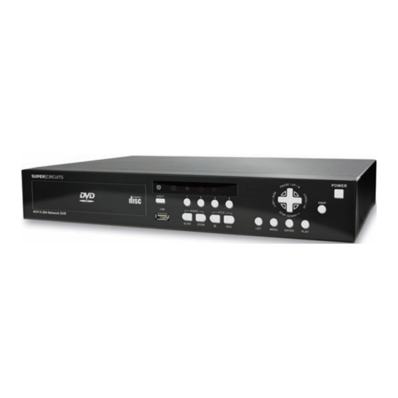
SECTION 1 Product Description The DMR40DVD, DMR41DVD, and DMR42DVD network DVRs includes H.264 technology for improved video quality, higher storage density, and faster file acquisition across the network. Recording backups can be performed through a USB port and/or an optional DVD writer. Depending on the model, they also support up to two internal SATA HDDs. -
Page 8: Package Contents
SECTION 1: PRODUCT DESCRIPTION 1.2 Package Contents Your DVR product includes the following: Digital video recorder (DVR) • HDD bracket and screws • Power adapter and power cord • D-sub connector • IR remote control • IR receiver (optional) • AAA size battery (2) •... -
Page 9: Front And Rear Panel Controls And Indicators
HDD is reading or recording DVR is powered on An alarm is triggered Timer recording is on Playback status (DMR40DVD only) HDD is full (DMR42DVD and DMR41DVD only) 2.1.2 Buttons MENU – Press MENU to open the main menu. ENTER – Press ENTER to apply and confirm the setting. - Page 10 SECTION 2: FRONT AND REAR PANEL CONTROLS – Press for 4 channel display mode. SEQ – Press to activate the call monitor function. Press again to exit Monitor mode. POWER – Press and hold for 5 seconds to turn the DVR on/off. When the DVR is recording mode, stop recording before turning off the DVR.
-
Page 11: Rear Panel
USB – Supports firmware upgrade and file backup. 2.2 Rear Panel DMR40DVD back panel 75Ω/HI-IMPEDANCE switch – Set this switch to HI-IMPEDANCE when using the LOOP connector to extend the INPUT signal to another device or INPUT channel. Otherwise, set to 75Ω. - Page 12 SECTION 2: FRONT AND REAR PANEL CONTROLS CALL – Connect to a sequencing call monitor. AUDIO channels 1, 2, 3, 4 – Connect to camera audio or other audio sources. The audio input is recorded when the associated video input channel is recorded. To make a video backup with audio, camera which supports the audio function must be NOTE connected to a video channel (INPUT) which supports audio recording.
-
Page 13: Connections And Setup
SECTION 3: CONNECTIONS AND SETUP SECTION 3 Connections and Setup The hard disk drive (HDD) included in your system is a security grade device, factory tested and certified to be functional with all operations of the DVR. NOTE Opening the DVR enclosure will void the warranty. If you need to change the HDD installed in your DVR, return the device to Supercircuits for a factory installation (preserves the warranty), or refer to the HDD compatibility list in Appendix C for recommended HDD models. - Page 14 SECTION 3: CONNECTIONS AND SETUP > > > OPENING THE DVR ENCLOSURE WILL VOID THE WARRANTY < < < The HDD may be installed in the left or right bracket: To install the HDD in the left bracket: Orient the HDD so that the circuit board side is facing up. Connect the power and data bus cables to the HDD.
-
Page 15: Hdd Installation For Dmr40Dvd
Reinstall the DVR top cover. Reconnect the power adapter. 3.1.2 HDD installation for DMR40DVD For DVRs with a DVD drive, the HDD is installed in the right side bracket. For DVRs without a DVD drive, the HDD is installed in the bracket on the left. - Page 16 SECTION 3: CONNECTIONS AND SETUP > > > OPENING THE DVR ENCLOSURE WILL VOID THE WARRANTY < < < Position the HDD in the bracket with the circuit board side toward the bracket. Secure the HDD to the bracket with four screws, two on each side. Connect the power and data bus cables to the HDD.
-
Page 17: Camera Connection
SECTION 3: CONNECTIONS AND SETUP > > > OPENING THE DVR ENCLOSURE WILL VOID THE WARRANTY < < < Reinstall the DVR top cover. Reconnect the power adapter. 3.2 Camera connection Refer to the documentation supplied with your camera for installation and setup instructions. For most cameras, the following must be completed before power is applied to the DVR. - Page 18 Pin 4: RS485-B Plug the RJ11 connector into the RS485 port. If an EXTERNAL I/O port is present on the DVR back panel (DMR40DVD only): At the DVR, remove the connector from the RJ11 cable and strip some insulation from the red and green wires.
- Page 19 SECTION 3: CONNECTIONS AND SETUP Plug the 15-pin D-sub connector into the EXTERNAL I/O port. At the camera, remove the RJ11 connector and insulation form the red and green wires in the cable. Connect the red wire (RS485-A signal) to the wire labeled RS485-A (or RS485+) at the speed dome camera.
-
Page 20: Dvr Software Usage
SECTION 4: DVR SOFTWARE USAGE SECTION 4 DVR Software Usage 4.1 Power on the DVR To power on the DVR: Power on all cameras connected to the DVR and wait until they initialize. Connect the DVR power cable to the power adapter and to the DVR, then plug the power adapter into an electrical outlet. -
Page 21: Menu Operations Keys
SECTION 4: DVR SOFTWARE USAGE SERIAL TYPE BAUD RATE HOST ID PASSWORD RESET DEFAULT CLEAR HDD SYSTEM INFO UPGRADE R.E.T.R. (MIN) (selected models) ADVANCED AUTO KEYLOCK (SEC) MENU LANGUAGE (cont.) VIDEO FORMAT VERSION QUICK SEARCH EVENT SEARCH EVENT INFO HDD INFO EVENT LOG USB BACKUP BACKUP... -
Page 22: Quick Start Menu
SECTION 4: DVR SOFTWARE USAGE Item Function Move to this item then press ENTER to go the next page. NEXT Move to this item then press ENTER to go the previous page. BACK Other operations in the ADVANCED menu are the same as in the QUICK START menu. 4.4 QUICK START menu Press MENU and enter the password to open the QUICK START menu. -
Page 23: Timer
SECTION 4: DVR SOFTWARE USAGE The QUICK START record submenu includes the following parameters: IMAGE SIZE – Select either FRAME, FIELD or CIF. • QUALITY – Select either SUPER BEST, BEST, HIGH or NORMAL. • IMAGE PER SECOND – Select the images per second for MANUAL RECORD. •... - Page 24 SECTION 4: DVR SOFTWARE USAGE The RECORD TIMER submenu is used to setup a recording schedule that repeats weekly. RECORD TIMER – Use the p and/or q buttons to change the setting (ON/OFF). When set to ON • press ENTER to open the submenu for setting the record time. X axis 0 ~ 24 hours.
-
Page 25: Date
SECTION 4: DVR SOFTWARE USAGE DETECTION TIMER – Use the p and/or q buttons to change the setting (ON/OFF). When it is • ON, press ENTER to open the submenu for setting detection sensing time. X axis 0 ~ 24 hours. Each time interval within a square is two hours divided into four 30-minute segments. Y axis Sunday ~ Saturday Operation... - Page 26 SECTION 4: DVR SOFTWARE USAGE The DATE submenu items are described below: DATE – Set the current date and time. The default order is YEAR / MONTH / DAY HOUR : MIN : • SEC. FORMAT – Select one date format from the following 3 options: Y/M/D, M/D/Y, D/M/Y. •...
-
Page 27: Setting The Date And Time
SECTION 4: DVR SOFTWARE USAGE 4.4.5 Setting the date and time Before using your DVR, set the current date and time. All recorded data is time stamped. DO NOT change the date or time of your DVR after recording anything. Otherwise, the data recorded will be disordered and it will be difficult to find information you may be searching for. -
Page 28: Advance Config
SECTION 4: DVR SOFTWARE USAGE 4.5 ADVANCE CONFIG The menu displays shown herein are for a 16-channel DVR. Displays for 8- and 4-channel units NOTE differ slightly. Press MENU and enter the password to open the QUICK START menu. Press the q button repeatedly to open the ADVANCE CONFIG menu. -
Page 29: Detection
SECTION 4: DVR SOFTWARE USAGE CAMERA submenu items are described below. While changing the camera setting, you can see the affect on the camera image. TITLE – The name of the camera channel. The default title is “CH” and the channel number. Move •... -
Page 30: Detection Area Setup
SECTION 4: DVR SOFTWARE USAGE Table 2. Detection area setup Press ENTER to confirm the start area. Transparent block indicates an area monitored for detection. Use the and/or buttons o choose the width of the Use the and/or buttons to choose the height of the detection area. -
Page 31: Alert
SECTION 4: DVR SOFTWARE USAGE SS – Spatial Sensitivity (on selected models). Use SS to set the sensitivity for detecting the size of • one object (the number of the grids) on the screen. A small value represents a higher sensitivity for motion detection. -
Page 32: Network
SECTION 4: DVR SOFTWARE USAGE The submenu items are described below: EXT. ALERT – Select ON or OFF to enable or disable a sound when any external alarm is triggered. • INT. BUZZER – Select ON or OFF to enable or disable a sound for all internal conditions: KEY, •... - Page 33 SECTION 4: DVR SOFTWARE USAGE 4.5.4.1 STATIC NETWORK menu NETWORK TYPE = STATIC opens the STATIC submenu with the following options. IP, GATEWAY, and NETMASK – Obtain this information from your ISP (Internet Service Provider) • and enter it into these fields. PRIMARY DNS/ SECONDARY DNS –...
- Page 34 SECTION 4: DVR SOFTWARE USAGE The PPPOE function requires a username and password subscribed from one ISP, and a DDNS NOTE account to transform the dynamic IP corresponding to a specific Hostname. NETWORK TYPE = DHCP opens the DHCP submenu with the following options. NETWORK TYPE –...
-
Page 35: Sntp
SECTION 4: DVR SOFTWARE USAGE The DHCP function must be supported by a router or a cable modem network with DHCP NOTE services and a DDNS service to transform the dynamic IP address to a specific Hostname. 4.5.5 SNTP Use this menu to synchronize your DVR time with networked computer systems. Move to SNTP then press ENTER to open the submenu. -
Page 36: Record
SECTION 4: DVR SOFTWARE USAGE The submenu parameters include: DE-INTERLACE – Select ON or OFF to enable or disable the de-interlace function. • If you set the recording image size as FRAME, set DE-INTERLACE to ON. If you set the recording NOTE image size as CIF, set DE INTERLACE to OFF. -
Page 37: Remote
SECTION 4: DVR SOFTWARE USAGE Submenu parameters include: MANUAL RECORD ENABLE – Set the manual recording function ON or OFF. • EVENT RECORD ENABLE – Set the event recording function ON or OFF. • TIMER RECORD ENABLE – Set the timer recording function ON or OFF. •... -
Page 38: Ptz Camera Setup
SECTION 4: DVR SOFTWARE USAGE Submenu parameters include: TITLE – Show the title of each channel set in the CAMERA menu. • DEVICE – Select the type of device (CAMERA/PTZ) on the channel. • ID – Set the ID number (0 ~ 255) for a PTZ camera. After connecting to a PTZ camera, the default •... -
Page 39: System Info
SECTION 4: DVR SOFTWARE USAGE 4.6 SYSTEM INFO Use this menu to setup several system level parameters including password and video format, and to initiate a firmware upgrade. Move to SYSTEM INFO, then press ENTER to open this submenu. The SYSTEM INFO screen shows the current settings. -
Page 40: Setting The Password
SECTION 4: DVR SOFTWARE USAGE AUTO KEYLOCK – Set the time-out in second after which the key lock function is activated. • Options are Never, 10 seconds, 30 seconds, or 60 seconds. LANGUAGE – Select the language of the OSD. •... -
Page 41: Quick Search
SECTION 4: DVR SOFTWARE USAGE 4.7.1 Quick Search Use this menu to search for events by time and play the file you find. Move to QUICK SEARCH, then press ENTER to open the submenu. Submenu parameters include: DATE – Select the time period (YEAR / MONTH / DAY HOUR : MIN : SEC) you want to search for. •... -
Page 42: Hdd Info
SECTION 4: DVR SOFTWARE USAGE Submenu parameters include: DATE – Set the date and time of the event you want to search for. • CHANNEL – Press the p and/or q buttons to select the channel. • EVENT – Select the event type: MOTION or ALARM. •... -
Page 43: Backup
SECTION 4: DVR SOFTWARE USAGE 4.8 BACKUP Press MENU and go to the BACKUP icon to open the BACKUP submenu. Clicking USB BACKUP or DISK BACKUP opens a submenu. H.264 Network DVR User Manual... -
Page 44: Usb Backup
SECTION 4: DVR SOFTWARE USAGE 4.8.1 USB BACKUP Video/audio files can be copied to a USB device, such as a USB flash memory drive, for archiving. Move to USB BACKUP, then press ENTER to open the USB BACKUP submenu. Before making USB backup, verify that: The USB flash drive is supported by your DVR (see Compatible USB Flash Drive). -
Page 45: Disk Backup (Selected Models)
SECTION 4: DVR SOFTWARE USAGE CHANNEL – Select channels by pressing ENTER to toggle the icon in front of the channel number. • - The R (checked box) icon indicates that this channel is selected for backup. - The icon indicates that this channel is not selected for backup. HDD NUM –... - Page 46 SECTION 4: DVR SOFTWARE USAGE Press MENU, go to the BACKUP menu, and select DISK BACKUP. Set the start time, end time, and select the channels and HDD to backup. Highlight START then press ENTER to begin the backup process. A completion indicator will appear.
-
Page 47: Basic Operation
SECTION 5: BASIC OPERATION SECTION 5 Basic Operation 5.1 Live page On the Live page, you can see a 1- , 4-, 9-, or 16-cut screen with status icons. See the following picture. System Time Status Bar Available Capacity Motion Channel Recording name... -
Page 48: Recording Icons
SECTION 5: BASIC OPERATION 5.1.1 Recording icons Continuous recording – By default, the record icon appears when the DVR is powered on and an HDD is installed. Event recording – When motion detection is sensed or an alarm is activated, the motion icon or alarm icon appears. -
Page 49: Key Lock And Unlock
SECTION 5: DVR SOFTWARE USAGE Press REW once to move one frame backward. — Stop – Pressing STOP during playback mode returns to live monitoring mode. • Slow Playback – Press SLOW to move forward at 1/4X speed playback; press twice to move •... -
Page 50: Search
SECTION 5: DVR SOFTWARE USAGE In the “Address Book” panel, select the IP address of your DVR (add the IP address of your DVR to the address book if necessary). Click the icon to show the Update Server panel. In Update Server, click the Firmware or Language tab as needed. Click Add and select the firmware or OSD files to upgrade. -
Page 51: Local And Remote Operation
SECTION 6: LOCAL AND REMOTE OPERATION SECTION 6 Local and Remote Operation Your DVR can be accessed from a personal computer (PC) for remote viewing of cameras and retrieval of stored video streams. DVRs can be setup for remote viewing across a private Local Area Network (LAN) and across a Wide Area Network (WAN), such as the internet, using the Video Viewer software provided on the CD with your DVR, Microsoft Internet Explorer... -
Page 52: Install Video Viewer Software
SECTION 6: LOCAL AND REMOTE OPERATION 6.2.1 Install Video Viewer software To install the Video Viewer software: Place the CD supplied with your DVR into your CD-ROM or DVD-ROM drive of your PC. Open the CD in a file browser, such as Windows explorer. Find the file named VideoViewer.exe or setup.exe. -
Page 53: Video Viewer Displays
SECTION 6: LOCAL AND REMOTE OPERATION 6.2.3 Video Viewer displays The Video Viewer simplified control panel is shown below. Clicking the Full Function Display Switch maintains the connection to the DVR and opens the Full Function Display. The Full Function display mode provides an enlarged view of the DVR screen and additional controls. H.264 Network DVR User Manual... -
Page 54: Video Viewer Button Functions
SECTION 6: LOCAL AND REMOTE OPERATION Table 4. Video Viewer button functions Button Function Description Simplified Full Function Click to show the predefined IP addresses. You can add, remove or Address Book search IP addresses to log into a DVR remotely. www.supercircuits.com... -
Page 55: Operations
SECTION 6: LOCAL AND REMOTE OPERATION Button Function Description Simplified Full Function Remote Click to go to the detailed DVR settings. Config Record Miscellaneous Click to go to the detailed record settings. Setting Control Click to choose a screen language. A Custom language change takes effect when the Setting... - Page 56 SECTION 6: LOCAL AND REMOTE OPERATION In the “Record Setting” window, you can set the following items: Record type • Hard disk overwrite • Pre- and post-alarm record time (in seconds) • Record time range • Recorded data storage location (Record Path) •...
- Page 57 SECTION 6: LOCAL AND REMOTE OPERATION To play a recording, select a log entry from the list and click Play, or double-click the entry. 6.2.4.3 Network Backup Click -> , or click to open the Backup window. Select the time range or event for which you want to make a video backup.
-
Page 58: E-Map Features
SECTION 6: LOCAL AND REMOTE OPERATION Table 5. Video Viewer backup window parameters Function Description HDD Number/ Specify the HDD number and channel associated with the video data you want. channel Download by Time In the “Start Time” and “End Time” columns specify the time range within which the video data was recorded. - Page 59 SECTION 6: LOCAL AND REMOTE OPERATION Before using this feature, connect Video Viewer to the devices you want to monitor. NOTE 6.2.5.1 Adding an E-Map group If Video Viewer is in simplified view mode, click to switch the control panel to the full-function view.
- Page 60 SECTION 6: LOCAL AND REMOTE OPERATION www.supercircuits.com...
-
Page 61: E-Map Device Tree Icons
SECTION 6: LOCAL AND REMOTE OPERATION When the E Map group is created, a tree appears on the top-left panel showing the devices you’ve added to this group. Table 6. E-Map device tree icons Icon Description The connected device is camera. When selected, it is red. The connected device is DVR. - Page 62 SECTION 6: LOCAL AND REMOTE OPERATION For a single E-Map group To edit or remove an existing single E-Map group, right-click on the group name to show the shortcut menu list. Select Edit E MAP or Remove E-MAP as required. For a building E-Map group To edit or remove an existing building E Map group, right-click on the group name to show the shortcut menu list.
- Page 63 SECTION 6: LOCAL AND REMOTE OPERATION To edit or remove a certain level of the building E Map group, right click on the level name. Select Edit E MAP or Remove E MAP as required. H.264 Network DVR User Manual...
-
Page 64: Web Browser
SECTION 6: LOCAL AND REMOTE OPERATION 6.3 Web browser You can view the images or operate your DVR with Microsoft Internet Explorer (IE), Mozilla Firefox, or Safari web browsers. The following operating systems are supported: Microsoft Windows 2000 • Microsoft Windows XP •... -
Page 65: Web Browser Button Function
SECTION 6: LOCAL AND REMOTE OPERATION Table 7. Web browser button function Function Description Home Click to go to the main page of the DVR. Config. Click to go to the detailed DVR setting. Click to enter PTZ mode. Click one of the numbers to switch to the channel you want to see in Channel Selection full screen mode. -
Page 66: Apple Quicktime Player
SECTION 6: LOCAL AND REMOTE OPERATION Function Description Click to take a snapshot of the current view and open another browser window to display Snapshot the captured image. Key Lock Click to enable the DVR key lock function. To unlock the DVR, enter your password, then click Enter. - Page 67 SECTION 6: LOCAL AND REMOTE OPERATION In the popup window, enter the Internet URL in the format rtsp://ipaddress:portnum/live/h264 (For example, rtsp://60.251.8.57:88/live/h264). ipaddress:portnum is the IP address and port number of your DVR. Click OK to continue. In the Internet Authentication window, enter the Userid and Password for accessing your DVR, then click OK to continue.
-
Page 68: Sc Mobile App For Iphone
SECTION 6: LOCAL AND REMOTE OPERATION If you’re not prompted to enter a Userid and Password, and the error message 10060 appears, NOTE go to Edit > Preferences > QuickTime Preferences, and select “Streaming Transport” from the drop-down list. Select “Use HTTP”, and keep the port ID as 80. When the login is successful, you will see the live view from the DVR. - Page 69 SECTION 6: LOCAL AND REMOTE OPERATION Store Icon Search for SC Mobile. After SC Mobile is found, select it. Install the application. Find the SC Mobile application on your phone application display. H.264 Network DVR User Manual...
-
Page 70: Setup
SECTION 6: LOCAL AND REMOTE OPERATION 6.5.2 Setup You can setup the SC Mobile application with at most one address book entry. When the application is first opened, the Addressbook will contain a default entry named “Demo Site”, with which you can become familiar with the application. - Page 71 SECTION 6: LOCAL AND REMOTE OPERATION Click the (Add) button in the lower left corner of the screen. A New Item entry will appear. Tap the Addressbook entry you added to highlight it, Submenu Icon then tap the submenu icon, , for additional settings.
-
Page 72: Using The Sc Mobile App
SECTION 6: LOCAL AND REMOTE OPERATION DMR40DVD-2, DMR41DVD-2 and The SC Mobile Audio feature is not functional with NOTE DMR42DVD-2 DVRs. On the Addressbook screen, tap the Settings button in the upper-right corner to configure the advanced options. These options include Auto login –... -
Page 73: Login To Your Dvr
SECTION 6: LOCAL AND REMOTE OPERATION 6.5.4 Login to your DVR Tap the entry in Adressbook to login to your DVR. SC Mobile will connect to your DVR and open a channel display. See the following screen captures. If you turn the iPhone sideways, and enlarged view of the channel display appears. - Page 74 SECTION 6: LOCAL AND REMOTE OPERATION IP Address – Shows the IP address or domain name of the connected device. Resolution – Shows the image resolution (in pixels). Quality – Shows the current image quality setting. Audio – Shows whether the audio function is set to ON or OFF. Frame Rate –...
-
Page 75: Ptz Camera Control
SECTION 6: LOCAL AND REMOTE OPERATION To view a single channel, press the button then press the channel number you want to see. • 6.5.6 PTZ camera control SC Mobile provides pan/tilt/zoom control of PTZ cameras. When a channel with PTZ features is displayed, icons located at the bottom of the screen can be used to control many pan/tilt/zoom functions. -
Page 76: Ptz Camera Control Buttons
SECTION 6: LOCAL AND REMOTE OPERATIONON Camera Control Buttons Table 8. PTZ Camera control buttons Button Description Slight zoom in – This zoom in mode allows greater zoom control than the touch and motion gestures on the camera image (see Step zoom in/out below). Slight zoom out –... -
Page 77: Swipe Left, Right, Up, Or Down
SECTION 6: LOCAL AND REMOTE OPERATION Button Description Preset – Depending on the camera’s capability, this feature allows you to preset a camera direction and zoom setup, and move the camera to that setup with a simple command. Up to six camera presets can be established. Setting a preset: Set the camera direction and zoom to a configuration you want to preset. -
Page 78: Logout
SECTION 6: LOCAL AND REMOTE OPERATION For example, to move the camera to the right, swipe the picture off to the left. 6.5.8 Logout Return to addressbook, or press the iPhone Home button to close app. www.supercircuits.com... -
Page 79: Specifications
SECTION 7: SPECIFICATIONS SECTION 7 Specifications Specifications shown in the following tables are subject to change without notice. Table 9. Specifications Model DMR42DVD DMR41DVD DMR40DVD Video system NTSC Video compression format H.264 Video input (Composite video signal 16 channels 8 channels 4 channels 1 Vp-p 75Ω... - Page 80 SECTION 7: SPECIFICATIONS Model DMR42DVD DMR41DVD DMR40DVD Licensed software Video Viewer/Microsoft Internet Explorer and Firefox web Network Surveillance Interface browsers/ Apple QuickTime/Apple Safari/Apple iPhone SC Mobile App Remote Independent Operation Network Alarm Notification E-mail and FTP server CMS (Central Management System) Yes (up to 16 IP addresses) R.E.T.R.
-
Page 81: Appendix A D-Sub Connector Pin Configuration
APPENDIX A: D-SUB CONNECTOR PIN CONFIGURATION APPENDIX A D-sub Connector Pin Configuration A.1 DMR42DVD 25-pin D-sub connector configuration Siren: When the DVR is triggered by alarm or motion, the COM connects with NO and the siren with strobe starts wailing and flashing. -
Page 82: Dmr41Dvd 25-Pin D-Sub Connector Configuration
APPENDIX A: D-SUB CONNECTOR PIN CONFIGURATION A.2 DMR41DVD 25-pin D-sub connector configuration Siren: When the DVR is triggered by alarm or motion, the COM connects with NO and the siren with strobe starts wailing and flashing. Magnetic Contact: When the magnetic contact is opened, the alarm will be triggered and the recording is on. -
Page 83: Dmr40Dvd 15-Pin D-Sub Connector Configuration
Magnetic Contact: When the magnetic contact is opened, the alarm will be triggered and the recording is on. Table 12. 25-pin D-sub configuration for DMR40DVD Function Description PIN OFF ALARM INPUT Connect ALARM INPUT (pin 3 – 6) and GND (pin 9) connector with wires. When an alarm is trig- gered, the DVR will start recording and the buzzer will be on. -
Page 84: Appendix B Compatible Usb Flash Drives
APPENDIX B: COMPATIBLE USB FLASH DRIVES APPENDIX B Compatible USB Flash Drives USB flash drives used for firmware upgrade and backup must be compatible with the DVR. If the USB flash drive is not compatible, the message USB ERROR is reported, or the flash drive will not function as expected. -
Page 85: Appendix C Compatible Hdd Models
APPENDIX C: COMPATIBLE HDD MODELS APPENDIX C Compatible HDD Models The DVR accommodates only SATA hard disk drives (HDDs). HDDs in the following list are known to be compatible with the DVR. Firmware upgrades may allow other models to also be compatible. Table 14. -
Page 86: Appendix D Troubleshooting Faq
APPENDIX D: TROUBLESHOOTING FAQ APPENDIX D Troubleshooting FAQ Refer to the table below for troubleshooting suggestions. The table includes typical problems and their solutions. Check these suggestions before calling your Supercircuits for support. Table 15. FAQ (Frequently Asked Questions) Questions Solutions Check power cord connection. - Page 87 APPENDIX D: TROUBLESHOOTING FAQ Questions Solutions Verify that your username and password is allowed. Failed to backup recorded files from a remote PC. Verify that the network connection setup is correct (IP Address/Port/User Name/Password). (For details, see “Network Specify the hard disk (HDD) number where the recorded data is saved. Specify the correct Backup”) channel.
-
Page 88: Appendix E: Rs232 Protocol
APPENDIX E: RS232 PROTOCOL APPENDIX E RS232 Protocol The DVR can be controlled through the RS232 interface from an ASCII terminal. The table below equates DVR functions and the ASCII command codes that produce them. Communication through the RS232 port uses a format of 8 bit data with 1 start bit and 1 stop bit. Table 16. - Page 89 APPENDIX E: RS232 PROTOCOL Function Code ASCII Function Code ASCII KEY_MODE 0x6f KEY_IRIS_FAR 0x68 KEY_4 CUT 0x61 KEY_PTZ_LIGHT 0x6c KEY_9 CUT 0x62 KEY_PTZ_WIPER 0x77 KEY_16 CUT 0x63 H.264 Network DVR User Manual...
-
Page 90: Appendix Fdvr Battery Replacement
APPENDIX F: DVR BATTERY REPLACEMENT APPENDIX F DVR Battery Replacement To maintain the correct time in the DVR system during a power interruption or shutdown, a battery is installed in the DVR. If the correct time is not maintained during these events, this battery may need to be replaced. -
Page 91: Appendix G Recording Time Table
APPENDIX G: RECORDING TIME TABLE APPENDIX G Recording Time Table The recording time capacity of your DVR depends on camera resolution, picture complexity, and frequency of the object movement. However, to approximate the recording time capacity of your DVR, measurements were made by sending a static image sent to each DVR channel and configuring each channel for the highest image quality and IPS rate. -
Page 92: Hdd Usage For 4 Channel Recording
APPENDIX G: RECORDING TIME TABLE Table 19. HDD usage for 4 channel recording Record mode Quality GB/Hour 750 GB Record Time (days) FRAME 1.23 25.41 FIELD BEST 1.104 28.31 1.062 29.43 www.supercircuits.com...
Need help?
Do you have a question about the DMR40DVD and is the answer not in the manual?
Questions and answers