Table of Contents
Advertisement
Quick Links
MDVR21SD
Advanced Solid State Mobile DVR
User Manual
Thank you for using our video recorder. This manual is applicable for 1ch, 2ch and 4ch SD Video Recorder. Please
read this User's Manual carefully to ensure that you can use the device correctly and safely. The contents of this
manual are subject to be changed without notice.
www.supercircuits.com
MDVR21SD_RM
1
Advertisement
Table of Contents

Related Manuals for Super Circuits MDVR21SD Series


Summary of Contents for Super Circuits MDVR21SD Series
-
Page 1: User Manual
MDVR21SD Advanced Solid State Mobile DVR User Manual Thank you for using our video recorder. This manual is applicable for 1ch, 2ch and 4ch SD Video Recorder. Please read this User’s Manual carefully to ensure that you can use the device correctly and safely. The contents of this manual are subject to be changed without notice. - Page 2 Warning This device is NOT of waterproof; to prevent it from any accident of fire or electric shock, please do NOT put any container with water on the device or nearby. Do not expose the device to moisture, or extreme temperatures. CAUTION RISK OF ELECTRIC SHOCK DO NOT OPEN...
-
Page 3: Table Of Contents
TABLE OF CONTENTS MDVR21SD ADVANCED SOLID STATE MOBILE DVR ......... 1 1. GENERAL INTRODUCTION .................. 5 2. PRODUCT FIGURES .................... 7 .................................. 7 RONT ANEL .................................... 8 EAR PANEL .............................. 9 IRELESS EMOTE ONTROLLER 3. INITIAL SET UP ...................... 9 ‐ .............................. ... - Page 4 5.9.3 Set Motion Sensitivity .............................. 2 9 ................................ 3 0 IDEO OST LARM ................................ 3 0 CHEDULE ECORDING ................................ 3 1 IDEO YSTEM ETTING ................................ 3 2 ET ATE AND 6.3.1 Set Date Display Format ............................ 3 2 ...
-
Page 5: General Introduction
1. General Introduction The MDVR21SD series mobile digital video recorder is a compact, full-featured recording system that uses a SD card as a storage device. The recorder unit and associated accessories are specifically designed for operation in a mobile environment. -
Page 6: Video And Audio
Video And Audio H.264 High Profile video compression, real time recording (25 fps (PAL) / 30 fps (NTSC) for each channel. Frame rate adjustable for each channel. Audio compression: G.711 codec. This codec offers high compression with high quality audio. ... -
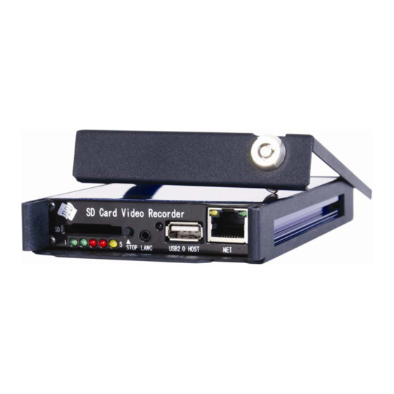
Page 7: Product Figures
2. Product Figures 2.1 Front Panel ①:SD Card Slot ②:Status Lights (Power, Run, Alarm, SD Card, Record Status) ③:Stop Button: For stop recording. ④:LANC Port: For connection to an Event Cable or a wired remote IR sensor harness (option) : Infra-Red receiver window. ⑥:USB Port: Can be used as a secondary recording device, such as a flash memory card. -
Page 8: Rear Panel
4. SD (Red) Description Writing data to the SD Card. Not writing – inactive. 5. REC (Yellow) Description Recording data. CAUTION: Do not attempt to remove the SD card while SYS mode is active. Select “STOP” on the front panel or remote control to stop recording. -
Page 9: Wireless Remote Controller
2.3 Wireless Remote Controller Power Alarm Digits Record Stop Play Audio Toggle Video Toggle 10. Left/Backspace 11. Menu/Enter 12. Right 13. ESC 14. Down 15. OK to confirm 16. Fast Forward 17. Next 18. Pause/Step 19. Fast Backward 20. Previous 21. - Page 10 Put the DVR system inside the bottom cover, and load a SD Card. NOTE: The lock jumper of SD Card should be in OFF position. Kingston Class 4 or above, Transcend Class 6 or above is recommended for fast write speed. Close with the top cover and lock it with keys supplied.
-
Page 11: Power Connection
3.2 Power Connection 3.2.1. Use Ignition Switch to Turn On/Off DVR System 3.2.2, Turn On / Off DVR System Automatically NOTE The DVR uses DC power input, please be very careful when connecting to the “+” and “-” of the power supply. Wide voltage range of 8V-32V for the DVR. -
Page 12: Camera Connection
To protect the battery from being damaged of short circuit, the fuse should be placed very closed to the “+” pole of car battery. 3.3 Camera Connection Two different kinds of Audio & Video Cables for option: 4-pin threaded cable with male connector for each camera (Pin 1: 12V power, Pin 2: GND, Pin 3: Audio Input, Pin 4: Video Input). - Page 13 NOTE: The camera should with 4-pin female connector to match this cable. The DVR system will provide stable 12V DC power to each camera, and record video and audio (if the camera is with microphone built-in). This type of connection cable is highly recommended. It saves both installation time and cost.
-
Page 14: Sensor Harness Connection
3.4 Sensor Harness Connection GPS Connection (Option) Description RXD2: Data receive GND: Ground +5V DC: Power output www.supercircuits.com MDVR21SD_RM... -
Page 15: Event Button And Cable Connection (Option)
3.5 Event Button and Cable Connection (Option) www.supercircuits.com MDVR21SD_RM... -
Page 16: Main System Overview
4. Main System Overview www.supercircuits.com MDVR21SD_RM... -
Page 17: Basic Operation And Menu System
5. Basic Operation and Menu System 5.1 SD Card Formatting For a brand new SD Card of SDHC standard, it can be used directly. But with situations listed below, you’re required to format it before using: If the SD Card is of SDXC standard (like a 64GB SD Card), the defaulted file format is exFAT, which will not be recognized by the DVR system. -
Page 18: Choose Recording Mode
The format process will take some time, please wait. You will see the capacity of SD card after formatting. 5.2 Choose Recording Mode Two recording modes for option: Composite Mode and Separate Mode. The defaulted recording mode is “Separate Mode”. You can change to “Composite Mode” by steps given as below if needed: Press <MENU>... -
Page 19: File Length
5.3 File Length Options for file length: 5mins, 10mins, 15mins, 20mins, 30mins, 45mins and 60mins. The defaulted file length is 5 minutes. The maximum file length is 60 minutes. 5.4 Recording Quality Press <MENU> to enter the DVR system menu, choose “RECORD” and enter its sub-menu, go to “RECORD SETTINGS”... - Page 20 Setting menu for Separate Mode: www.supercircuits.com MDVR21SD_RM...
-
Page 21: Start Recording
Parameters for image quality levels: Quality Resolution Still Image Movement Image Audio Bitrate File Capacity Bitrate (Bit/s) Bitrate (Bit/s) (Bit/s) BASIC 2/3 D1 350K 210K 198M/hour ( PAL: 480*384, NTSC: 480*320 ) NORMAL 1000K 600K 324M/hour ( PAL: 720*576, NTSC: 720*480 ) GOOD 1200K 720K... -
Page 22: Playback Option
Quad Images in Separate Mode: 5.6 Playback Option 5.6.1 Playback files on DVR system www.supercircuits.com MDVR21SD_RM... - Page 23 Play-back the latest record file(s) directly. In “Separate Mode”, you can playback archive file when recording. Press <PLAY> by remote, it will playback the latest file of first camera channel (ch: 01). Use < >< >< >< > or number key “1”, “2”, “3”, “4” to select a specific camera channel, and press <PLAY>...
- Page 24 Press <OK> or <MENU> by remote to enter a specific directory. All record files of the specific hour will be listed (The file with an ‘A’ suffix refers to Alarm Recording). Use< >/< > to turn a page. > to choose a file, and press <PLAY> to playback. By pressing <OK> or <MENU> , Use <...
-
Page 25: Playback The Files On Manufacturer's Pc Playback Software
You can press “Play” to playback the file, or “Save As” to copy the file to an USB flash drive. To stop playback, press <STOP> by remote. 5.6.2 Playback the files on manufacturer’s PC Playback Software Install “PC Playback Software.exe” included on the CD onto your PC; Remove the SD card from DVR system, and read on a PC by using a SD card reader, then run the PC Playback Software to playback the files. - Page 26 LABEL Color Description SENSOR1 Brown Sensor(Alarm) 1 SENSOR2 Brown Sensor(Alarm) 2 SENSOR3 Brown Sensor(Alarm) 3 SENSOR4 Violet Speed Sensor Press <MENU> by remote to enter the DVR system menu, choose “RECORD” and press <MENU> to enter its sub-menu, go to “RECORD SETTINGS” and press <MENU> to enter. The defaulted “REC MODE” is “AUTO”, change it to “MANUAL”...
-
Page 27: Post Event Record
When alarm recording is trigged, a yellow blinking dot will be displayed on the top right corner. Remarks for each option: NO.: SENSOR 1, SENSOR 2, SENSOR3. RECORD: Choose the channel(s) to start to record when the sensor(alarm) recording is triggered. There are a total of 16 modes: OFF, CH 01, CH 02, CH 01+02, CH 03, CH 01+03, CH 02+03, 01+02+03, CH 04, CH 01+04, CH 02+04, 01+02+04, CH 03+04, 01+03+04, 02+03+04, ALL. -
Page 28: Motion Detection
5.9 Motion Detection 5.9.1 Set Motion Detection Zone Press <MENU> by remote to enter the DVR system menu, choose “ALARM”, go to “MOTION ZONE” and press <MENU> to set the area: Choose the zone(s) which you want to monitor by using < >... -
Page 29: Set Motion Sensitivity
5.9.3 Set Motion Sensitivity Press <MENU> to enter the DVR system menu, choose “ALARM” to enter its sub-menu, go to “MOTION SENSITIVITY”, and press < > or < > to sensitive level (1~9 levels for option). “1” refers to lowest sensitive level, and “9”... -
Page 30: Video Lost Alarm
6.0 Video Lost Alarm The buzzer can be set as “ON” to trigger the beeper when any video lost. Press <MENU> to enter the DVR system menu, choose “ALARM” and press <MENU> to enter its sub-menu, go to “VIDEO LOST” and set the buzzer as “ON”, press <OK>... -
Page 31: Video System Setting
6.2 Video System Setting Press <MENU> to enter the DVR system menu, Choose ”System” to enter its sub-menu, set the “VIDEO FORMAT” as PAL or NTSC, and press <OK> to save and exit. www.supercircuits.com MDVR21SD_RM... -
Page 32: Set Date And Time
6.3 Set Date and Time 6.3.1 Set Date Display Format Press <MENU> to enter the DVR system menu, choose “SYSTEM” and press <MENU> to enter its sub-men, go to “TIME ZONE” and set the “DATE FORMAT”, “YY/MM/DD”, “MM/DD/YY” or “DD/MM/YY”. 6.3.2 Set The Time Zone Press <MENU>... -
Page 33: Configuration Setup
6.4 Configuration Setup Press <MENU> to enter the DVR system menu, choose “SYSTEM” to enter its sub-menu, go to “CONFIG SETUP” and press <MENU> to enter, and customize your configuration. 1) User Config Save If some system configurations are modified, and you want to make a save copy for this, please choose “USER CONFIG SAVE”... -
Page 34: User Level And Password Setting
6.5 User Level and Password Setting The defaulted system enter is with no password. To set the user name and password, Press <MENU> to enter the DVR system menu, choose “SYSTEM” and press <MENU> to enter its sub-menu, set the “LOGIN VERIFY” to be “YES”, press <OK> to save and exit. Escape from the DVR system menu, when enter again, you will be required for use name: www.supercircuits.com MDVR21SD_RM... -
Page 35: Network Setting
The system is defaulted to be entered with no password. If password is required, go to “NEW PASSWORD” and set the password. Input the same password in both rows of “New Pass” and “Pass Confirm”, press <OK> or <MENU> to save and exit. 6.6 Network Setting The system supports both Static IP and Dynamic IP. -
Page 36: Motor
After setting, please press <MENU> or <OK> to save and exit. If it is dynamic IP, the system will configure the IP address automatically. ”HOST NAME” is used for setting the DVR system’s name. 6.7 MOTOR 6.7.1 Set “LICENSE ID” and “LINE” Press <MENU>... -
Page 37: Get Speed From Gps
6.7.2 Get Speed from GPS Pin No. Description Color Description GPS Connector TXD1 Vacant TXD, COM1, (GPS) TXD2 Vacant TXD, COM2 485A Vacant RS485 A, (PTZ) 5.0V +5 VDC Pin 9 SNR2 Grey Sensor 2 SPEED Violet Speed sensor RXD1 Vacant RXD, COM1, (GPS) RXD2... - Page 38 GPS connector (RS232 COM1) Description RXD2: Data receive GND: Ground +5V DC: Power output Connect GPS receiver to DVR system through the sensor harness: Press <MENU> to enter DVR system menu, choose “MOTOR” and press <MENU> to enter its sub-menu, set the “SPEED CHECK”...
-
Page 39: Get Speed From Speedometer
3) The speed will be displayed on the left bottom of the monitor. If you need the speed to be “MPH” other than “KM/H”, please select “mile” in the “PULSES UNIT”. NOTE: If no GPS device is connected to the DVR system, speed on monitor will stay as “0.0KMH”. To hide this information, set the “SPEED CHECK”... - Page 40 If the speedometer does NOT have a signal output wire, please connect to the output of speed sensor. This could also be input of the speedometer. Press <MENU> to enter DVR system menu, choose “MOTOR” and press <MENU> to enter its sub-menu, set the “SPEED CHECK”...
-
Page 41: Manage The Power
8 or 16 pulses if the wheel goes one round and you need to calculate the number of the pulse that the speed sensor will generate if the car runs for one kilometer. Then set the number to “Pulse No.”. While in a real application, it’s not easy to pulse number by the calculation on the paper. -
Page 42: 2, Turn On / Off Dvr System Automatically
NOTE: If the vehicle uses low level as ignition signal, you need to set the “IGNITION SIGNAL” as “LOW LEVEL” . 6.8.2, Turn On / Off DVR System Automatically Connect the DVR system to car battery as diagram shown below. Note: Please connect the yellow wire (ignition wire) to the “+”... -
Page 43: Use Ptz
6.9 Use PTZ 6.9.1 PTZ Control Connect the RS485 of DVR system to PTZ communication port. Press <MENU> to enter DVR system menu, choose “LIVE” and press <MENU> to enter its sub-menu, go to “PTZ PARAMETER” and press <MENU> to enter, set the “PTZ CONTROL” as “ON”, set other parameter if needed. -
Page 44: Rename The Camera
6.9.2 Rename the camera Press <MENU> to enter the DVR system menu, choose “LIVE” to enter its sub-menu, go to “OSD” and set it as “ON”, Press <MENU> to enter the DVR system menu, choose “LIVE” to enter its sub-menu, go to “CAMERA TITLE” and press <MENU>... -
Page 45: Gps Setting (Option)
6.10 GPS Setting (Option) Press <MENU> to enter the DVR system menu, choose “GPS” to enter its sub-menu. The DVR system will check the GPS device automatically. If a GPS device is found to be connected, the “GPS DEVICE” will show “GPS OK”; if no GPS device is found, it will show “GPS NONE”. ”GPS BURNIN”... - Page 46 NOTE: The time you set will reflect to the recording time once Event Button is pressed. To take the defaulted “15s” for an example, the alarm recording will last for 15 minutes since the Event Button is pressed, then stop. If you use Separate Mode for recording, press <MENU>...
- Page 47 CH 01+04, CH 02+04, 01+02+04, CH 03+04, 01+03+04, 02+03+04, ALL. The defaulted camera channel is CH 01. In Composite Mode, the quad mode will be regarded as “CH 01”. You can also set up the text you want to display in the "TIP" of “ALARM ACTION”. The text you set will be displayed if the event is triggered.
-
Page 48: Firmware Update
the exact application before mass production. 6.12 Firmware Update Copy the update file to the root directory of SD card. The update file has the postfix of "tar". Insert the SD card into the SD card slot on front panel of the DVR system, press <MENU> by remote to enter the DVR system menu. -
Page 49: Module (Option )
NOTE: Do not turn off the power while updating! “Upgrade Success” will be shown up to remind you when update is successful, press <MENU> by remote to restart the application. 6.13 Using Wi-Fi Module (Option) Debug the Wi-Fi module on PC a) Connect Wi-Fi module to a PC’s USB and LAN ports;... - Page 50 choose , then go with “NEXT” to finish the installation. c) After that, you will find on your desktop. Double-click this icon to run the software, select your WiFi bridge from the list and click “Next”: d) Select a wireless network to connect to: www.supercircuits.com MDVR21SD_RM...
- Page 51 For an example, if you select the “ES_LINK_TENDA” to connect to, press “Next”, input the ascii code of your password in hex format. You can look up the ascii code of your password in the ascii table (Appendix A). For an example, if your password is "hello", you should input 68656c6c6f in “Key1”, then press “Next”...
- Page 52 e) If now your PC could access to internet through this Wi-Fi module, it means the Wi-Fi module has been debugged well. You may remove the Wi-Fi module from your PC, and connect to DVR’s USB and LAN ports, power on the DVR.
-
Page 53: Connection & Installation Cables
7. Connection & Installation Cables 7.1 Power Supply Cable Viewed from crimp side: Mark Color Description “+” of power supply (you can connect to Battery “+”) YELLOW Ignition signal. Connect this wire to “+” of power supply if you don’t use ignition to control the power. -
Page 54: Video & Audio Input / Output Cable
BLACK “-” of power supply (you can connect to Battery “-”) 7.2 Video & Audio Input / Output Cable Video& Audio Input Cable Viewed from crimp side: Mark Color Description BNC Connector, in Yellow Video input RCA Connector, in White Audio input DC Connector, in Black Power output for camera(+12 VDC, Maximum current 1A) -
Page 55: Sensor Harness
RCA Connector, in White Audio output DC Connector, in Black Power output for camera(+12 VDC, Maximum current 1A) Ground 7.3 Sensor Harness Pin No. Description Color Description GPS Connector TXD1 Vacant TXD, COM1, (GPS) TXD2 Vacant TXD, COM2 485A Vacant RS485 A, (PTZ) 5.0V +5 VDC... - Page 56 Description RXD2: Data receive GND: Ground +5V DC: Power output www.supercircuits.com MDVR21SD_RM...
-
Page 57: Specification
8. Specification SPECIFICATION ITEM MDVR21SD VIDEO INPUT 4 channels VIDEO OUTPUT 1 channel, 1.0V, p-p, 75Ω, BNC VIDEO FORMAT Support PAL/NTSC VIDEO COMPRESSION H.264 High Profile VIDEO RECORD RESOLUTION 1280x1024(PAL) / 1248x832(NTSC) FRAME RATE 100fps(D1 PAL) / 120fps(D1 NTSC) VIDEO BITRATE 1.98Mbps ~ 4.5Mbps, 4 level video quality AUDIO INPUT 4 channels... -
Page 58: List Of Standard Accessories
SPECIFICATION SIZE 12cm X 9cm X 2cm (4.75" x 3.5" x 0.8") WEIGHT 0.3KG PACKAGE SIZE AND 21cm X 14cm X 7.5cm (8.3” x 5.5” x 3.0”), 0.63KG WEIGHT 9. List of Standard Accessories Item Description Quantity SD Video Recorder 1 pc Tamperproof &Lock 1 pc... -
Page 59: Trouble Shooting
10. Trouble Shooting. 1. Q : After connecting the DVR power, no video output, No.1 and No.2 indicators lights on panel flashing alternately. A: The No.1 and No.2 indicator light is “Power” and “Run”. If the 2 indicators lights are flashing alternatively, the DVR missed the ignition signal, please check if the yellow line of the input power lines has connected with the power positive level, or if it’s the same as the setting of the effective electrical level in menu settings. - Page 60 time period you set. 8. Q: Do your SD Card DVR support the capacity of 64G and above SDXC card? A: The DVR support the capacities of 64G and above SDXC cards, but currently, DVR doesn’t support for ExFAT file system completely, we suggest that you format the SDXC card to FAT32 file system under Windows system before using.
- Page 61 Power indicator light Running indicator light Description running indicator light indicator light Flashing simultaneously with Flashing simultaneously with Ignition signal disappears, DVR running indicator light power indicator light countdown running. After the time setting in the" ignition delay ", DVR off automatically.
- Page 62 RS485 control PTZ functions. If you do need PTZ control function, please contact sales when ordering. 16. Q: I bought the mobile DVR with PTZ control function, but it has no response after PTZ connecting. A: After you have confirmed your machine already has PTZ control function, you may test your control functions in accordance with the following: 1, Exchange the two lines of 485A and 485B, to see if they are connected wrong;...
- Page 63 it will occur when the DVR settings is PAL system, while the camera is NTSC system. Conversely, if the DVR is set with NTSC system, scrolled fault images also occur when connecting a camera with PAL system. 21. Q: when retrieving record files on the machine, only find the record files of channel 1, how to find the files of the other channels? A: Press the <left>...
- Page 64 State of green State of green Meaning Meaning light light One slow flash Communication of Slow flash every every three System start wire control is not three seconds seconds normal One flash every System is normal but One flash every No memory device second no record...
Need help?
Do you have a question about the MDVR21SD Series and is the answer not in the manual?
Questions and answers