Table of Contents
Advertisement
Ducted Split
Wine Cellar Cooling Systems
Installation, Operation and Maintenance Guide
SS025, SS050, SS088, SS200
Manufactured by:
Syracuse, NY
Wine Guardian reserves the right, without notice, to make changes to this document at its sole discretion.
Please visit our web site for the most current version of the Wine Guardian manual and other literature.
Wine Guardian is a registered trademark (2,972,262) of Air Innovations, Inc.
Edition 10/2012
© Air Innovations, 2012
1
Advertisement
Table of Contents
Troubleshooting

Related Manuals for Wine Guardian SS025


Summary of Contents for Wine Guardian SS025
- Page 1 Wine Guardian reserves the right, without notice, to make changes to this document at its sole discretion. Please visit our web site for the most current version of the Wine Guardian manual and other literature. Wine Guardian is a registered trademark (2,972,262) of Air Innovations, Inc.
-
Page 2: Table Of Contents
TABLE OF CONTENTS Directory of Terms......................5 Illustrations ........................6 Receiving, Inspecting and Unpacking the Wine Guardian Unit ........7 Review the Packing Slip to Verify ..................7 Check the fan coil unit for: ....................7 Check the condensing unit for ....................7 General Description...................... - Page 3 Standard Controller Functions ..................45 Inspection and Start Up Checklists ................50 Receiving and Inspecting ......................50 Handling and Installing ......................50 Starting-up the Unit .......................50 Platform Mount ........................50 Starting-up and Operating the Wine Guardian Split System ......... 51 Turn on the Unit ........................51...
- Page 4 Testing the Fan ........................51 Running the Unit ........................51 Cycling the Unit ........................52 Setting the Remote Interface Controller ................52 Regulating the Wine Cellar Temperature ................52 Changing the Air Flow Direction ....................52 Maintenance ........................53 General ..........................53 Cleaning the Condensate Drain System ................54 Cleaning the Humidifier ......................54 Heating Coil Option .......................54 Maintenance Schedule ....................
-
Page 5: Directory Of Terms
Heat Gain / Loss – The amount of cooling or heating expressed in watts transferred between the wine cellar and the ambient space. The Wine Guardian must offset this heat/gain loss. Inlet Air – The air returning from the wine room to the Wine Guardian fan coil. I.D. – Inside diameter NEC –... -
Page 6: Illustrations
Illustrations Overview of the Wine Guardian fan coil .............. 11 Refrigeration Illustration of the Wine Guardian fan coil ........11 Ducted split system specifications sheet ............. 13 Wiring diagrams for ¼ and ½ ton units ..............14 Wiring diagram for the 1-ton unit ................. 15 Wiring diagram for the 2-ton unit ................. -
Page 7: Receiving, Inspecting And Unpacking The Wine Guardian Unit
Guardian fan coil and condensing unit. These ship from separate manufacturing facilities and therefore may not arrive on the same date and time. Each Wine Guardian component is shipped in a corrugated box. A shipment may include one or more boxes containing accessories. -
Page 8: General Description
Wine Guardian uses digital electronic controls and R-134a refrigerant. The entire Wine Guardian fan coil section is tested at the factory and the condensing unit is shipped separately. All components are of a high quality standard commercial grade. The entire system is approved by ETL according to UL 1995 and CSA safety standards. -
Page 9: Wine Guardian Fan Coil Unit
The Wine Guardian fan coil section operates as air passes through the cooling coil and is cooled by the refrigerant inside the coil. This causes any excess humidity in the air to condense and be captured in the drain pan and piped outside the unit. -
Page 10: Accessories And Optional Equipment
Duct Collars and Flexible Ducts Ducting for the Wine Guardian is sold in kits by size for each unit. Each kit contains two adapter collars, one 25 foot length of round flexible duct and two straps. The number of duct kits needed depends on the wine cellar layout and application. -
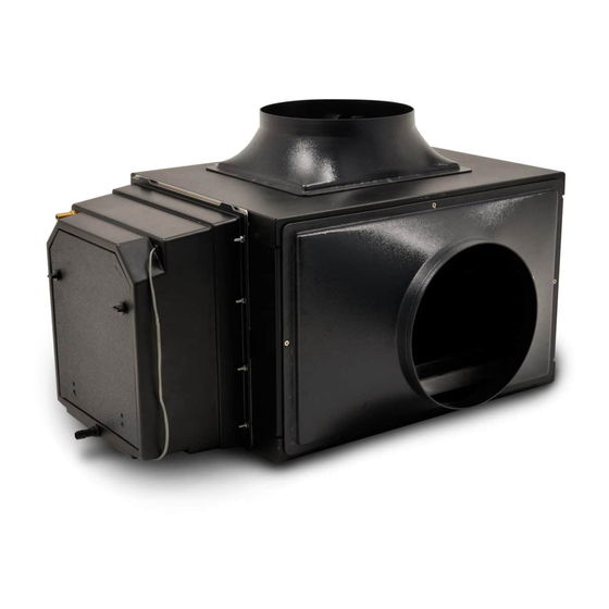
Page 11: Overview Of The Wine Guardian Fan Coil
Overview of the Wine Guardian fan coil Fig. 1 Fig. 2... - Page 12 Fig. 3 Model Number SS025 SS050 SS088 SS200 Dimensions - Nominal A – Width Inches 14.00 22.00 22.00 22.375 B – Height Inches 14.132 14.132 14.132 18.00 C – Length Inches 16.75 16.75 16.75 20.50 D – Evap. Discharge (OD) Inches 7.94...
-
Page 13: Ducted Split Systems Specifications Sheet
Ducted split system specifications sheet... -
Page 14: Wiring Diagram For 1/4-Ton And 1/2-Ton Units
Wiring Diagram for SS025 and SS050 Units Fig. 4... -
Page 15: Wiring Diagram For 1-Ton Unit
Wiring Diagram for SS088 Units Fig.5... -
Page 16: Wiring Diagram For 2-Ton Unit
Wiring Diagram for SS200 Units Fig. 6... -
Page 17: 24-Volt Contactor Detail Sheet
24-Volt Contactor Detail Sheet Fig. 7... -
Page 18: Safety
Following is a typical example of a Caution message as it could appear in the manual: CAUTION RISK OF PERSONAL INJURY OR DAMAGE TO EQUIPMENT Improper installation may result in the equipment malfunctioning and a safety hazard. Read all of the installation instructions before installing the Wine Guardian unit. -
Page 19: Lockout/Tagout Procedure
Lockout/Tagout Procedure 1) Turn off the power switch (indicator light should be off) 2) Unplug the unit from the electrical outlet and cover the outlet to prevent accidently plugging in the unit. 3) Turn off circuit breaker or disconnect switch at condensing unit. Safety Considerations The equipment covered by this manual is designed for safe and reliable operation when installed and operated within its designed specifications. -
Page 20: Equipment Safety Interlocks
Main Power Switch The main power switch is located on the side of the Wine Guardian unit. (See Fig.1 on page 36) It shuts off the power to the fan coil unit. A separate disconnect switch will be wired to the condensing unit. - Page 21 CAUTION Clean only with a dry cloth. Never pressurize equipment above specified test pressure. See Wine Guardian Specification sheet on page 13. Do not use the Wine Guardian near water. Do not block any supply or return air register or duct. Install in accordance with the instructions in this manual.
-
Page 22: Installation
Installation CAUTION SHARP EDGES RISK OF SERIOUS INJURY Sharp edges are present inside the Wine Guardian system Pre-installation Test Test the system before installing it to check for non-visible shipping damage. To test the Wine Guardian fan coil section: Set the system on the floor or a sturdy level surface.... - Page 23 Use only dedicated power outlet boxes of the correct capacity and configuration for the unit model. CAUTION RISK OF PERSONAL INJURY OR DAMAGE TO EQUIPMENT Improper installation may result in the equipment malfunctioning and a safety hazard. Read all of the installation instructions before installing the Wine Guardian unit.
-
Page 24: Planning The Installation
Planning the Installation IMPORTANT Installation of residential and commercial split systems must be performed by qualified service technicians with proper training in the installation, start up, service, and repair of these systems. Certification to handle refrigerants is also required. Addressing Items in the Planning Process ... -
Page 25: Installing The Fan Coil Unit
NOTE: Review Fig. 1 through Fig. 4 on the following pages before mounting the unit Floor Mounting Mount the Wine Guardian fan coil on a plywood surface at least 12 inches above the floor to keep it away from water. Allow adequate space for the external drain. -
Page 26: Ceiling Mounting
Construct a structurally sound, level platform to place the unit on when hanging it from the ceiling joists. The Wine Guardian is NOT designed to be suspended from the top of the unit; it must be supported from the bottom. Angle brackets are available as an option for these types of applications. -
Page 27: Rod Mount
Rod Mount Fig.2 Shelf Mount Fig. 3 Optional ductwork connection on same wall Fig. 4... -
Page 28: Installing The Ductwork And Grilles
Recommended Insulated Flexible Ductwork Sizing Chart for the Evaporator (cooling) Coil Outlet Outlet Inlet (Return Air) Model# (supply air) (supply air) Single Single Single 8” 6” 8” SS025 10” 10” 10” SS050 10” 10” 10” SS088 12” 12” 12” SS200 CAUTION RISK OF DAMAGE TO EQUIPMENT Avoid crimping the flexible ducts. -
Page 29: General Duct Recommendation
Check that all the fan blades move freely. Check for loose foreign objects in any of the air paths. Connect the round flexible ducts to the Wine Guardian using the duct collars provided with the duct accessory kit. -
Page 30: Installing The Condensate Drain Connection
Empty the bucket periodically. The Wine Guardian unit is provided with a built-in drain trap. The drain trap creates a water seal to prevent air from backing up into the drain pan and causing the drain pan to overflow. Do not create secondary traps in the external drainline. -
Page 31: Wiring The Fan Coil Unit For Power
The electrical outlet and wiring installation must meet the national and local building codes. Match the electrical wiring to the cord provided on the Wine Guardian. Provide dedicated circuit and wiring for the system. Match the wiring and breaker size to the rated load as shown on the serial plate and in this guide. -
Page 32: Installing The Condensing Unit
Installing the Condensing Unit Condensing units are factory assembled with a sheet metal outdoor hood for protection from the elements. A minimum of 12 inches is required around the perimeter of the condensing unit for proper airflow across the coil, and to provide an adequate discharge airflow path through the louver section. -
Page 33: Split System Interconnecting Line Sizing Chart
“total” line lift insulation length (height) evaporator thickness evaporator (OD) (in) (OD) 1/4” 1/4” 3/8” 3/8” 3/8” 50’ 15’ SS025 1/4” 1/4” 1/2” 3/8” *3/8” 50’ 15’ SS050 SS088 3/8” *1/4” 1/2” 5/8” 1/2” 50’ 15’ 3/8” 3/8” 7/8”... -
Page 34: Sample Piping Configurations
Sample Piping Configurations Incorrect Installation Correct Installation Evaporator Evaporator Condenser Condenser Creates an oil trap Evaporator Evaporator Condenser Condenser Creates an oil trap Oil runs away Condenser from condenser Condenser Evaporator Evaporator Condenser Condenser Soft copper sages and Evaporator creates an oil trap Evaporator... -
Page 35: Leak Checking And Evacuation Process
Leak Checking and Evacuation Process WARNING ALL COMPONENTS CHARGED WITH DRY AIR MUST BE EVACULATED BEFORE CHARGING WITH REFRIGERANT Purge the dry air charge from the unit by opening the liquid line shut-off valve or removing the liquid line outlet fitting or plug, whichever is applicable for your particular unit. -
Page 36: Refrigerant Charging
Refrigerant Charging NOTE: The SS025, SS050, SS088 systems utilize a Headmaster control valve to control head pressure at low ambient applications, therefore require a specific initial charging procedure as outlined below. The SS200 system does not use this method of low ambient control (utilizes fan cycling), but can accept initial charge into the liquid receiver port the same way and the system has the same capacity. -
Page 37: Procedures For Charging System With Head Pressure Control
Procedures for Charging System with Head Pressure Control (SS025, SS050, SS088) NOTE: When charging any system with head pressure control the outdoor ambient temperature must be known. Charging of Systems with Head Pressure Control in ambients above 70 degrees F (After normal evacuation procedures): 1. -
Page 38: Superheat
SS025, SS050 SS0088, SS200 3/8” OD ~ 1.0 ounce/foot **Based on factory testing using 25 feet of interconnected piping SS025 = 35 ounce total charge SS050 = 39 ounce total charge SS088 = 60 ounce total charge SS200 = 73 ounce total charge... -
Page 39: Split System Operations Chart
Split System Operations Chart OD Ambient (F) Suction (psig) Discharge (psig) Superheat (F) Sub-cooling (F) SS050 OD Ambient (F) Suction (psig) Discharge (psig) Superheat (F) Sub-cooling (F) SS088 OD Ambient (F) Suction (psig) Discharge (psig) Superheat (F) Sub-cooling (F) SS200 -- Available soon OD Ambient (F) Suction (psig) Discharge (psig) Superheat (F) Sub-cooling (F) -
Page 40: Installing The Remote Interface Controller And Communication Cable
See below for remote sensor installation details. IMPORTANT Wine Guardian units are supplied with 50 feet of Cat 3, 6-wire twisted pair communication cable with RJ-11 connectors. Failure to use this type of communication cable WILL cause product damage and WILL void any equipment warranty. - Page 41 Attach backing plate to wall using the two screws provided with the system. (Fig .5) Fig. 4 5. Re-install plastic face plate on to backing plate. Fig. 5 6. Re-attach the communication cable to the side of the Wine Guardian cooling unit. (Fig. 6) Fig. 6...
-
Page 42: Installing The Wine Guardian Remote Sensor
Fig. 1 Mounting the Remote Sensor 1. Disconnect the communication cable from the side of the Wine Guardian unit and the remote sensor. Install the communication cable within the wall and/or ceiling structure of the wine cellar to the desired controller mounting location. - Page 43 (Fig. 4) 6. Plug the remote sensor cables into the splitter device at the Wine Guardian unit along with the communication cable for the remote interface controller. (Fig. 5)
-
Page 44: Joining The Communication Cable
Joining the Communication Cable IMPORTANT Wine Guardian cooling systems are supplied with 50 feet Cat 3 of 6-wire, twisted pair communication cable with RJ11 type connectors. Caution must be taken when connecting two lengths of communication cable (splicing) to ensure uniform wire color before and after splice. -
Page 45: Standard Controller Functions
Humidity setpoint. Press the “Up” or “Down” arrows to adjust the humidity to the desired set point. NOTE: Wine Guardian humidifier must be installed and setting six set to “1” or “2” before the controller will display and allow for changing percent humidity. - Page 46 Factory default is zero (0). Zero (0) = No humidifier One (1) = Stand-alone remote mounted humidifier Two (2) = Integral Wine Guardian mounted humidifier Fan AUTO or ON Setting 7 Press “Mode” button to advance to Setting 7.
- Page 47 9 through 19. for access code Compressor anti- Setting 9 short cycling time WINE GUARDIAN DOES NOT RECOMMEND SETTINGS LOWER THAN FACTORY DEFAULT. Press “Mode” button to advance to Setting 9. Press the “Up” or “Down” arrow buttons to adjust to the desired time in one (1) minute increments.
- Page 48 Differential Setting 16 Press “Mode” button to advance to Setting 16. temperature Press the “Up” or “Down” buttons to adjust to adjustment the desired set point. This setting changes the system/compressor and turns on temperature above setpoint. Factory default is set to +1 Example: Sensor reading = 55 Deg F Setting 16 Set to +3...
- Page 49 Alarm Codes High temperature Press the “Up” or “Down” arrow once to change alarm screen from alarm to normal Temperature and Humidity indication. “Hi Temp” will remain on screen until temperature falls below the High Temperature Alarm set point (Setting 3). Press the “Up”...
-
Page 50: Inspection And Start Up Checklists
Inspection and Start Up Checklists Receiving and Inspecting Unit received undamaged Unit received complete as ordered including accessories Handling and Installing Unit mounted on solid level surface Sufficient space allowed for access to unit and accessories Proper electrical service ... -
Page 51: Starting-Up And Operating The Wine Guardian Split System
Starting-up and Operating the Wine Guardian Split System Now that the installation is complete, check to make sure all ductwork and electrical connections are secure. Replace all panels that were removed during installation. Check that all of the openings in the unit are covered with a blank panel, a ductwork connection or a grille. -
Page 52: Cycling The Unit
Changing the Air Flow Direction The optional grilles furnished with Wine Guardian are single directional. Rotate the grilles to change the direction of the air flow. When using multiple supply ductwork, it is necessary to balance the air flow between the ductwork. -
Page 53: Maintenance
RISK OF SEROUS INJURY SHARP EDGES ARE PRESENT ON THE FAN WHEELS, HOUSING, FINS AND COILS. NOTE: Maintenance on Wine Guardian units requires working with high voltage and sheet metal with possible sharp edges. Only qualified personnel should perform maintenance. -
Page 54: Cleaning The Condensate Drain System
Cleaning the Condensate Drain System The condensate drain system traps dust and dirt. Clean the drain system once a year. 1. Shut off the rocker switch and unplug the unit. 2. Remove the duct on the evaporator inlet. 3. Inspect the drain pan under the coil. 4. -
Page 55: Maintenance Schedule
Maintenance Schedule Monthly (or quarterly depending on experience with individual cellar) Check and drain trap – clean if needed. Check for noise or vibration. Check for short-cycling of the unit – a turning on and off of the compressor unit more than eight times/hour. -
Page 56: Troubleshooting
Troubleshooting WARNING BEFORE PROCEEDING, READ AND UNDERSTAND THE SAFETY INFORMATION CONTAINED IN THE SAFETY SECTION OF THE WINE GUARDIAN MANUAL. IMPORTANT This section is intended as a diagnostic aid only. For detailed repair or parts replacement procedures, contact a qualified service company. Check the following table for some... -
Page 57: Unit Is Operating And Blows Evaporator Air
Unit is operating and blows evaporator air, but the supply air is not colder than the return air from the cellar Possible Cause Solution Remote interface controller not set up Check remote interface controller setup in the properly manufactures guide Compressor not operating High pressure switch open (button up) Alarm will appear on remote interface controller... -
Page 58: Humidity Too Low, Without Optional Humidifier
Humidity too low, without optional humidifier Possible Cause Solution No moisture being added to cellar Add Wine Guardian humidifier or a room humidifier Humidity too low, with optional humidifier Possible Cause Solution Humidifier not operating Check wiring for loose, broken or frayed... -
Page 59: Unit Operates But The Power Switch Light Is Not On
Unit operates but the power switch light is not ON Possible Cause Solution Bulb is burned out Replace bulb Unit is leaking water Possible Cause Solution Piping from unit to drain is trapped Re-pipe to remove external traps Trap plugged Clean trap Condensate pan plugged Remove blockage and clean... -
Page 60: High Pressure Switch Has Shut The Unit Down
High Pressure Switch has Shut the Unit Down Every Wine Guardian unit has a manual reset high pressure switch in the refrigeration system. This switch shuts the compressor and condenser down if the head pressure in the system is too high. -
Page 61: Advanced Troubleshooting
Advanced Troubleshooting IMPORTANT This section is intended for qualified refrigeration service technicians only. The technician should repeat all of the previous troubleshooting steps before taking action on these more technical solutions. Evaporator Coil is Freezing Possible Cause Solution Charge too low Check sight glass Check for leaks Add refrigerant... -
Page 62: Contact And Warranty Information
Warranty and Warranty Procedure The Wine Guardian unit serial number is noted on all packing lists and bills of lading and, along with the shipping date, is kept on file at Wine Guardian for warranty purposes. All correspondence regarding warranty must include the model number and serial number of the unit involved. Note that the warranty is null and void if the serial number on the unit or compressor is altered, removed or defaced.
Need help?
Do you have a question about the SS025 and is the answer not in the manual?
Questions and answers