Wine Guardian WGS40 Installation, Operation And Maintenance Manual
Ducted split wine cellar cooling systems
Hide thumbs
Also See for WGS40:
- Installation, operation and maintenance manual (83 pages) ,
- Quick start installation manual (40 pages) ,
- Installation, operation and maintenance manual (70 pages)
Table of Contents
Advertisement
Quick Links
Ducted Split
Wine Cellar Cooling Systems
Installation, Operation and Maintenance Guide
WGS40, WGS75, WGS100, WGS175
Manufactured by:
Syracuse, NY
www.wineguardian.com
www.airinnovations.com
Wine Guardian reserves the right, without notice, to make changes to this document at its sole discretion.
Please visit our web site for the most current version of the Wine Guardian manual and other literature.
Wine Guardian is a registered trademark (2,972,262) of Air Innovations, Inc.
Edition 02-2014
© Air Innovations, 2014
1
Advertisement
Table of Contents
Troubleshooting

Related Manuals for Wine Guardian WGS40


Summary of Contents for Wine Guardian WGS40
- Page 1 Wine Guardian reserves the right, without notice, to make changes to this document at its sole discretion. Please visit our web site for the most current version of the Wine Guardian manual and other literature. Wine Guardian is a registered trademark (2,972,262) of Air Innovations, Inc.
-
Page 2: Table Of Contents
Table of Contents Directory of Terms ......................4 Illustrations ........................5 Receiving, Inspecting and Unpacking the Wine Guardian Unit ........9 Review the Packing Slip to Verify ..................9 Check the fan coil unit for: ...................... 9 Check the condensing unit for ....................9 General Description ....................... - Page 3 Changing Jumper Positions (Averaging reading from Remote Sensor) ..........52 Standard Controller Functions ..................53 Inspection and Start-up Checklists ................. 60 Handling and Installing ......................60 Starting-up the Unit ........................ 60 Starting-up and Operating the Wine Guardian Split System .......... 61 Turn on the Unit ..........................61...
- Page 4 Testing the Fan ..........................61 Running the Unit ........................62 Cycling the Unit ........................62 Setting the Remote Interface Controller ................. 62 Regulating the Wine Cellar Temperature ................62 Changing the Air Flow Direction ..................... 63 Maintenance ......................... 64 Cleaning the Filters ........................ 65 Cleaning the Condensate Drain System ................
- Page 5 Heat Gain / Loss – The amount of cooling or heating expressed in watts transferred between the wine cellar and the ambient space. The Wine Guardian must offset this heat/gain loss. Inlet Air – The air returning from the wine room to the Wine Guardian fan coil. I.D. – Inside diameter NEC –...
-
Page 6: Illustrations
Illustrations Overview of the Wine Guardian fan coil .............. 13 Refrigeration Illustration of the Wine Guardian fan coil ........13 Ducted split system specifications sheet ............. 14 Wiring diagram for WGS40 ................. 15 Wiring diagram for WGS75 ................. 16 Wiring diagrams for the WGS100 and WGS175 ..........17 24-volt contactor detail sheet ................ -
Page 7: Receiving, Inspecting And Unpacking The Wine Guardian Unit
Guardian fan coil and condensing unit. These ship from separate manufacturing facilities and therefore may not arrive on the same date and time. Each Wine Guardian component is shipped in a corrugated box. A shipment may include one or more boxes containing accessories. -
Page 8: General Description
Wine Guardian uses digital electronic controls and R-134a refrigerant. The entire Wine Guardian fan coil section is tested at the factory and the condensing unit is shipped separately. All components are of a high quality standard commercial grade. The entire system is approved by ETL according to UL 1995 and CSA safety standards. -
Page 9: Wine Guardian Fan Coil Unit
The Wine Guardian fan coil section operates as air passes through the cooling coil and is cooled by the refrigerant inside the coil. This causes any excess humidity in the air to condense and be captured in the drain pan and piped outside the unit. -
Page 10: Accessories And Optional Equipment
Duct Collars and Flexible Ducts Ducting for the Wine Guardian is sold in kits by size for each unit. Each kit contains two adapter collars, one 8m length of round flexible duct and two straps. The number of duct kits needed depends on the wine cellar layout and application. -
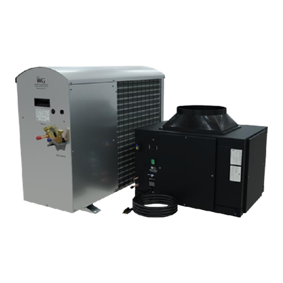
Page 11: Overview Of The Wine Guardian Fan Coil
Overview of the Wine Guardian fan coil Fig. 1 Fig. 2... - Page 12 Fig. 3 Model Number WGS40 WGS75 WGS100 WGS175 Dimensions - Nominal A – Width 35.6 55.9 55.9 56.8 B – Height 35.9 35.9 35.9 45.7 C – Length 42.5 42.5 42.5 52.1 D – Evap. Discharge (OD) 20.2 25.2 25.2 30.3...
-
Page 13: Wiring Diagram For Wgs40
Wiring Diagram for WGS40 Fig. 4... -
Page 14: Wiring Diagram For Wgs75 Units
Wiring Diagram for WGS75 Units Fig.5... -
Page 15: Wiring Diagram For Wgs100, Wgs175 Units
Wiring Diagram for WGS100, WGS175 Units Fig. 6... -
Page 16: 24-Volt Contactor Detail Sheet 24
24-Volt Contactor Detail Sheet 24 Fig. 7... -
Page 17: Condensing Section Wiring Schematic For Wgs040
Condensing Section Wiring Schematic for WGS040... - Page 18 Condensing Section Wiring Schematic for WGS75...
-
Page 19: Condensing Section Wiring Schematic For Wgs100
Condensing Section Wiring Schematic for WGS100... -
Page 20: Condensing Section Wiring Schematic For Wgs175
Condensing Section Wiring Schematic for WGS175... -
Page 21: Safety
Safety IMPORTANT The equipment described in this manual uses electricity. When using this equipment, be sure to follow the safety procedures outlined in this manual. Safety Message Conventions Safety messages contained in this manual, DANGER, WARNING, and CAUTION are bold and highlighted in red for quick identification. -
Page 22: Lockout/Tagout Procedure
RISK OF PERSONAL INJURY OR DAMAGE TO EQUIPMENT Improper installation may result in the equipment malfunctioning and a safety hazard. Read all of the installation instructions before installing the Wine Guardian unit. Lockout/Tagout Procedure 1) Turn off the power switch (indicator light should be off) 2) Unplug the unit from the electrical outlet and cover the outlet to prevent accidently plugging in the unit. -
Page 23: Electrical Shock Hazards
Main Power Switch The main power switch is located on the side of the Wine Guardian unit. (See Fig.1 on page 36) It shuts off the power to the fan coil unit. A separate disconnect switch will be wired to the condensing unit. - Page 24 Fan impellers continue to turn (free-wheel) after the power is shut off. CAUTION Clean only with a dry cloth. Never pressurize equipment above specified test pressure. See Wine Guardian Specification sheet on page 13. Do not use the Wine Guardian near water. Do not block any supply or return air register or duct.
-
Page 25: Installation
Installation CAUTION SHARP EDGES RISK OF SERIOUS INJURY Sharp edges are present inside the Wine Guardian system SHARP EDGES RISK OF SERIOUS INJURY Sharp edges are present inside the Wine Guardian system. Pre-installation Test Test the system before installing it to check for non-visible shipping damage. -
Page 26: Air Flow Diagram
Use only dedicated power outlet boxes of the correct capacity and configuration for the unit model. CAUTION RISK OF PERSONAL INJURY OR DAMAGE TO EQUIPMENT Improper installation may result in the equipment malfunctioning and a safety hazard. Read all of the installation instructions before installing the Wine Guardian unit. -
Page 27: Planning The Installation
Planning the Installation IMPORTANT Installation of residential and commercial split systems must be performed by qualified service technicians with proper training in the installation, start up, service, and repair of these systems. Certification to handle refrigerants is also required. Addressing Items in the Planning Process ... -
Page 28: Installing The Fan Coil Unit
NOTE: Review Fig. 1 through Fig. 4 on the following pages before mounting the unit Floor Mounting Mount the Wine Guardian fan coil on a plywood surface at least 30cm above the floor to keep it away from water. Allow adequate space for the external drain. -
Page 29: Ceiling Mounting
Construct a structurally sound, level platform to place the unit on when hanging it from the ceiling joists. The Wine Guardian is NOT designed to be suspended from the top of the unit; it must be supported from the bottom. Angle brackets are available as an option for these types of applications. -
Page 30: Rod Mount
Rod Mount Fig.2 Shelf Mount Fig. 3 Optional ductwork connection on same wall Fig. 4... -
Page 31: Installing The Ductwork And Grilles
Inlet (Return Air) (supply air) (supply air) Model# Single Single Single WGS40 WGS75 WGS100 WGS175 CAUTION RISK OF DAMAGE TO EQUIPMENT Avoid crimping the flexible ducts. This chokes down the inside area and reduces the airflow, causing the unit to operate erratically. -
Page 32: General Duct Recommendation
Check that all the fan blades move freely. Check for loose foreign objects in any of the air paths. Connect the round flexible ducts to the Wine Guardian using the duct collars provided with the duct accessory kit. -
Page 33: Installing The Condensate Drain Connection
Empty the bucket periodically. The Wine Guardian unit is provided with a built-in drain trap. The drain trap creates a water seal to prevent air from backing up into the drain pan and causing the drain pan to overflow. -
Page 34: Wiring The Fan Coil Unit For Power
RISK OF SERIOUS INJURY OR DEATH The electrical outlet and wiring installation must meet the national and local building codes. Match the electrical outlet to the plug provided on the Wine Guardian. Provide dedicated circuit and wiring for the system. ... -
Page 35: Installing The Condensing Unit
Installing the Condensing Unit Condensing units are factory assembled with a sheet metal outdoor hood for protection from the elements. A minimum of 30cm is required around the perimeter of the condensing unit for proper airflow across the coil, and to provide an adequate discharge airflow path through the louver section. -
Page 36: Split System Interconnecting Line Sizing Chart
(height) evaporator insulation evaporator (OD) mm thickness (OD) mm WGS40 WGS75 WGS100 WGS175 *Interconnecting tube must be reduced down at evaporator connection Notes: Line lengths are expressed in equivalent feet = actual run length + fitting allowances (i.e. ~5’ for each bend/elbow allowance). -
Page 37: Sample Piping Configurations
Sample Piping Configurations Incorrect Installation Correct Installation Evaporator Evaporator Condenser Condenser Creates an oil trap Evaporator Evaporator Condenser Condenser Creates an oil trap Oil runs away from condenser Condenser Condenser Evaporator Evaporator Condenser Condenser Soft copper sages and Evaporator creates an oil trap Evaporator... -
Page 38: Leak Checking And Evacuation Process
Leak Checking and Evacuation Process WARNING ALL COMPONENTS CHARGED WITH DRY AIR MUST BE EVACUATED BEFORE CHARGING WITH REFRIGERANT Purge the dry air charge from the unit by opening the liquid line shut-off valve or removing the liquid line outlet fitting or plug, whichever is applicable for your particular unit. -
Page 39: Wiring
Refrigerant Charging NOTE: The WGS40,.WGS75. WGS100 systems utilize a Headmaster control valve to control head pressure at low ambient applications, therefore require a specific initial charging procedure as outlined below. The wgs175 system does... -
Page 40: Determining The Amount Of Charge
However, this is not satisfactory and if the system is to function properly year-round, the correct amount of extra charge must be calculated ahead of time. Procedures for Charging System with Head Pressure Control WGS40, WGS75, WGS100,WGS175) NOTE: When charging any system with head pressure control the outdoor ambient temperature must be known. - Page 41 Charging of Systems with Sporlan Head Pressure Control in ambient below 20 degrees C (After normal evacuation procedures): NOTE: When charging in ambient below 20 Deg. C the procedure is very critical. Be sure to adhere to the following steps. Failure to do so will result in overcharging the system.
-
Page 42: Superheat
To give you an idea on how much R134A refrigerant charge you may require to reach full charge for your given interconnecting line length, see the very general guidelines below based on liquid line size: WGS40, WGS75 63mm OD ~ ..45g/m WGS100, WGS175 1cm OD ~ .90 g/m... -
Page 43: Split System Operations Chart
Split System Operations Chart WGS40 OD Ambient (F) Suction (kPa) Discharge (kPa) Superheat C) Sub-cooling (C) 1130 1365 WGS75 OD Ambient (F) Suction (kPa) Discharge (kPa) Superheat (F) Sub-cooling (F) 1234 1482 WGS100 G100 Suction (kPa) Discharge (kPa) Superheat (F) Sub-cooling (F) -
Page 44: Installing The Thermostat And Communication Cable
See below for remote sensor installation details. IMPORTANT Wine Guardian units are supplied with 6m of Cat 3, 6-wire twisted pair communication cable with RJ-11 connectors. Failure to use this type of communication cable WILL cause product damage and WILL void any equipment warranty. -
Page 45: Mounting The Remote Interface Controller
Mounting the Remote Interface Controller Disconnect the communication cable from the side of the Wine Guardian unit and the Remote Interface Controller. a) Install the communication cable within the wall and/or ceiling structure of the wine cellar to the desired controller mounting location. - Page 46 Attach backing plate to wall using the two screws provided with the system. (Fig.5) Fig. 4 Fig. 4 5. Re-install plastic face plate on to backing plate. 6. Re-attach the communication cable to the side of the Wine Guardian cooling unit. (Fig.6) Fig. 5 Fig. 6...
-
Page 47: Installation Of The Wine Guardian Remote Sensor
Installation of the Wine Guardian Remote Sensor The Remote Sensor is a combination temperature and humidity sensor only. It is designed to be mounted within the wine cellar and can be used in combination with the Remote Interface Controller or up to three additional Remote Sensors to read and control multiple areas within the wine cellar. - Page 48 Mount the Remote Sensor on a solid surface away from doors, corners, air outlets, drafts or heat generating equipment. Do not mount the Remote Sensor directly on an outside wall or wall adjacent to a boiler room. Use a piece of foam insulation behind the sensor to insulate it from a hot or cold surface.
-
Page 49: Joining Communication Cable
Joining Communication Cable Important Wine Guardian cooling systems are supplied with 15 meters of 6 wire, Cat 3 twisted pair communication cable with RJ11 type connectors. Caution must be taken when connecting two lengths of communication cable (splicing) to ensure uniform wire color before and after splice. -
Page 50: Changing Jumper Positions (Averaging Reading From Remote Sensor)
Changing Jumper Positions (Averaging reading from Remote Sensor) If using multiple Remote Temperature/Humidity sensors in your application, refer to the photos showing the need to change the jumper locations internal to the control board on each remote sensor (up to 3 maximum). For the control to average all of the sensors utilized (if more than one), the jumper must be in different positions on the pins. -
Page 51: Standard Controller Functions
Press the “Up” or “Down” arrows to adjust the humidity to the desired set point. Note – a Wine Guardian humidifier must be installed and setting six (6) set to “1” or “2” before the controller will let you change... - Page 52 Settings – Press and hold the “Settings” button for five (5) seconds to access the following settings. Deg F or Deg C Setting 1 Press the “Down” arrow to change temperature from Deg F to Deg C. Press the “Up” arrow to change temperature from Deg C to Deg F.
- Page 53 Setting 6. Press the up or down arrow buttons to adjust to the desired set point. Factory default is zero (0) One (1) = Integral Wine Guardian mounted humidifier 一 Two (2) = Stand-alone remote mounted humidifier Fan AUTO or ON Setting 7 ...
- Page 54 Compressor anti-short cycling time is the amount of allowable time between compressor stop and restart. Rapid start/stop of compressors can cause premature failure. Factory default is 5 minutes. WINE GUARDIAN DOES NOT RECOMMEND SETTINGS LOWER THAN FACTORY DEFAULT. Set up remote sensor Setting 10 ...
- Page 55 Room sensor Setting 15 Press “Settings” button to advance to Setting 15. calibration Press the “Up” or “Down” buttons to adjust to the desired set point. Maximum setting is +2°C, minimum setting is -2°C. Factory default is zero (0).
- Page 56 Alarm Codes High temperature Press the “Up” or “Down” arrow once to change alarm (!) screen from alarm to normal Temperature and Humidity indication. “Flashing temperature number” Along with flashing (!) symbol will remain on screen Flashing until temperature falls below the High Temperature temperature Alarm set point (Setting 3).
- Page 57 Press the “Up” or “Down” arrow once to change !2 = CS (Condensate screen from alarm to normal Temperature and Switch Fault) Humidity indication. THIS ALARM FORCES THE SYSTEM TO SHUT DOWN. The “!2” will remain on screen until the CS (condensate switch) fault is resolved and reset.
-
Page 58: Inspection And Start-Up Checklists
Inspection and Start-up Checklists Unit received Unit received complete as ordered including accessories Handling and Installing Unit mounted on solid level surface Sufficient space allowed for access to unit and accessories Proper electrical service provided ... -
Page 59: Starting-Up And Operating The Wine Guardian Split System
Starting-up and Operating the Wine Guardian Split System Now that the installation is complete, it’s time to start the unit up. Check to make sure all ductwork and electrical connections are secure. Replace all panels which were removed during installation. Check that all of the openings in the unit are covered with a blank panel, a ductwork connection or a grille. -
Page 60: Running The Unit
Running the Unit Check unit to confirm the compressor is running, such as the hum of the compressor or cool air leaving the unit. √ Initially, the unit may run continuously for several hours, up to a day or more, while it lowers the cellar temperature. -
Page 61: Changing The Air Flow Direction
Changing the Air Flow Direction The grilles furnished with Wine Guardian are single directional. Rotate the grilles to change the direction of the air flow. When using multiple supply ductwork balance the air flow between the ductwork. If too much air flows though one duct but not enough air flows from the other duct, install a damper or other restriction into the duct with too much air. -
Page 62: Maintenance
If mold is found, remove it immediately and sanitize that portion of the unit. The Wine Guardian is designed for minimum maintenance. The refrigerant system is hermetically sealed and requires no maintenance. The fans are permanently lubricated and require no maintenance. -
Page 63: Cleaning The Filters
Cleaning the Filters The evaporator and condenser coils are provided with reusable, washable air filters. The filters protect the coils from becoming coated or plugged by dust. Frequency of cleaning the filters is based on the amount of dust or dirt generated in the cellar or basement. 。... -
Page 64: Cleaning The Condensate Drain System
Cleaning the Condensate Drain System The condensate drain system traps dust and dirt. Clean the drain system once a year. 1. Shut off the rocker switch and unplug the unit. Remove the grille or duct on the evaporator inlet. Remove the filter and inspect the drain pan under the coil. 2. -
Page 65: Maintenance Schedule
Maintenance Schedule Monthly (or quarterly depending on experience with individual cellar) Check filter and drain trap – clean if needed. Check for noise or vibration. Check for short-cycling of the unit – a turning on and off of the compressor unit more than either (8) times/hour. -
Page 66: Troubleshooting
Troubleshooting WARNING BEFORE PROCEEDING, READ AND UNDERSTAND THE SAFETY INFORMATION CONTAINED IN THE SAFETY SECTION OF THE WINE GUARDIAN MANUAL IMPORTANT This section is intended as a diagnostic aid only. For detailed repair or parts replacement procedures, contact a qualified service company. Check the following table for some solutions before calling a service technician. -
Page 67: Problems Controlling Cellar Temperature
No power to thermostat Check wiring for loose broken or frayed connections Check transformer for 24v output Power Switch Light is On and the Thermostat Light is On Possible Cause Solution Thermostat is not set up properly Check thermostat set up in the guide. Press fan ON switch to check evaporator fan only. -
Page 68: Problems Controlling Cellar Humidity
Defective Thermal Expansion Valve If under warranty call for service If not under warranty call a refrigeration technician Humidity too low, without optional humidifier Possible Cause Solution No moisture being added to cellar Add Wine Guardian humidifier or a room humidifier... - Page 69 Humidity too low with optional humidifier Possible Cause Solution Humidifier not operating Check wiring for loose, broken or frayed connections Check humidistat set up Check for water flow & solenoid valve operation Check damper operation Humidifier operating Check for water being hot Check drip pad –...
-
Page 70: Other Miscellaneous Problems
High Pressure Switch has Shut the Unit Down Every Wine Guardian unit has a manual reset high pressure switch in the refrigeration system. This switch shuts the compressor and condenser down if the head pressure in the system is too high. -
Page 71: Instructions To Reset High Pressure Switch
Instructions to Reset High Pressure Switch Remove the access panel, grille or duct collar at the condenser opening labeled “High Press. Manual Reset Switch ----- “Remove panel or grille to access” Locate the high pressure switch near the compressor (a cylindrical device piped into the refrigeration system with two wires a red button on the top). -
Page 72: Advanced Troubleshooting
Advanced Troubleshooting IMPORTANT THIS SECTION IS INTENDED FOR QUALIFIED REFRIGERATION SERVICE TECHNICIANS ONLY. THE TECHNICIAN SHOULD REPEAT ALL OF THE PREVIOUS TROUBLESHOOTING STEPS BEFORE TAKING ACTION ON THESE MORE TECHNICAL SOLUTIONS. Evaporator Coil is Freezing Possible Cause Solution Charge too low Check sight glass Check for leaks Add refrigerant... -
Page 73: Instructions To Reset High Pressure Switch
High Pitched or Loud Rubbing Noise, Clanking or Vibration Possible Cause Solution Fans loose or malfunctioning Repair or replace Excessive compressor vibration Replace TXV malfunctioning Repair or replace Replacing the Blowers When replacing the fan or motor, replace the fan and motor as a unit. Do not remove the motor from the impeller wheel. -
Page 74: Contact And Warranty Information
Warranty and Warranty Procedure The Wine Guardian unit serial number is noted on all packing lists and bills of lading and, along with the shipping date, is kept on file at Wine Guardian for warranty purposes. All correspondence regarding warranty must include the model number and serial number of the unit involved. -
Page 75: Warranty
Warranty GENERAL Wine Guardian warrants, to the original buyer, its goods and all parts thereof to be free from defects in material and workmanship for a period of two (2) years from the date of invoicing assuming NORMAL USE AND SERVICE.。...
Need help?
Do you have a question about the WGS40 and is the answer not in the manual?
Questions and answers