Table of Contents
Advertisement
Quick Links
Advertisement
Table of Contents
Troubleshooting

Related Manuals for Canon iPF8000 series


Summary of Contents for Canon iPF8000 series
-
Page 1: Service Manual
R2 - CONFIDENTIAL Service Manual iPF8000 series iPF8300 Mar 2 2010... - Page 3 Canon will release technical information as the need arises. In the event of major changes in the contents of this manual over a long or short period, Canon will issue a new edition of this manual.
-
Page 4: Symbols Used
Introduction Symbols Used This documentation uses the following symbols to indicate special information: Symbol Description Indicates an item of a non-specific nature, possibly classified as Note, Caution, or Warning. Indicates an item requiring care to avoid electric shocks. Indicates an item requiring care to avoid combustion (fire). Indicates an item prohibiting disassembly to avoid electric shocks or problems. - Page 5 Introduction The following rules apply throughout this Service Manual: 1. Each chapter contains sections explaining the purpose of specific functions and the relationship between electrical and mechanical systems with refer- ence to the timing of operation. In the diagrams, represents the path of mechanical drive; where a signal name accompanies the symbol , the arrow indicates the direction of the electric signal.
-
Page 7: Table Of Contents
Contents Contents Chapter 1 PRODUCT DESCRIPTION 1.1 Product Overview ............................1- 1 1.1.1 Product Overview ..............................1- 1 1.2 Features ..............................1- 3 1.2.1 Features .................................. 1- 3 1.2.2 Printhead ................................. 1- 3 1.2.3 Ink tank ..................................1- 3 1.2.4 Cutter unit ................................1- 4 1.2.5 Roll holder ................................ - Page 8 Contents 2.2 Firmware ..............................2- 5 2.2.1 Operation Sequence at Power-on..........................2- 5 2.2.2 Operation Sequence at Power-off..........................2- 6 2.2.3 Print Position Adjustment Function ..........................2- 7 2.2.4 Head Management ..............................2- 7 2.2.5 Printhead Overheating Protection Control .......................2- 7 2.2.6 Pause between Pages .............................2- 7 2.2.7 White Raster Skip ..............................2- 7 2.2.8 Sleep Mode................................2- 7 2.2.9 Hard Disk Drive................................2- 7...
- Page 9 Contents 4.1 Service Parts ..............................4- 1 4.1.1 Service Parts ................................4- 1 4.2 Disassembly/Reassembly...........................4- 2 4.2.1 Disassembly/Reassembly ............................4- 2 4.3 Points to Note on Disassembly and Reassembly ..................4- 5 4.3.1 Note on locations prohibited from disassembly ....................... 4- 5 4.3.2 Moving the carriage manually..........................
- Page 10 Contents 7.1.2 Map of the Service Mode ............................7- 2 7.1.3 Details of Service Mode ............................7- 9 7.1.4 e-Maintenance/imageWARE Remote ........................7- 26 7.1.5 Viewing PRINT INF..............................7- 36 7.2 Special Mode............................7- 46 7.2.1 Special Modes for Servicing ..........................7- 46 Chapter 8 ERROR CODE 8.1 Outline ................................
-
Page 11: Chapter 1 Product Description
Chapter 1 PRODUCT DESCRIPTION... -
Page 13: Product Overview .......................................................................................................................................1
Contents Contents 1.1 Product Overview ................................1-1 1.1.1 Product Overview ..................................1-1 1.2 Features ..................................1-3 1.2.1 Features ......................................1-3 1.2.2 Printhead ...................................... 1-3 1.2.3 Ink tank ......................................1-3 1.2.4 Cutter unit ....................................1-4 1.2.5 Roll holder ....................................1-4 1.2.6 Stand ......................................1-5 1.2.7 Media take-up unit .................................. -
Page 15: Product Overview
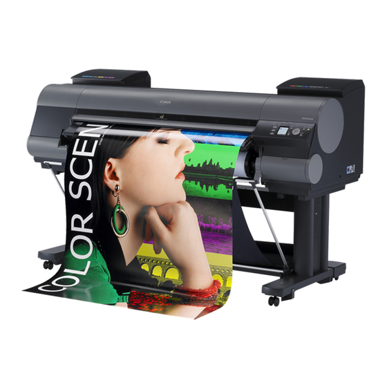
Chapter 1 1.1 Product Overview 1.1.1 Product Overview 0024-9412 This printer is a large-format printer that prints in a maximum width of 44 inches with high-speed photographic picture quality. This printer is a stand-mounted type printer and is capable of output to either roll media or cut sheet. [15] [14] [10]... - Page 16 Chapter 1 [17] [16] [18] [19] [21] [20] F-1-2 T-1-1 Upper Cover [12] Stand Ink Tank Cover [13] Maintenance Cartridge Cover Ejection Slot [14] Maintenance Cartridge Ejection Guide [15] Operation Panel Output Stacker [16] Ethernet Port Roll Holder Slot [17] USB Port Holder Stopper [18]...
-
Page 17: Features
Chapter 1 1.2 Features 1.2.1 Features 0024-9414 - Media pass in widths up to 44 inches (1117.6 mm). - Large ink tanks save the need for their replacement. - Uninterrupted printing from subtanks. - BK and MBK inks are loaded concurrently to eliminate the need for their replacement. - Media take-up unit (option) is supported. -
Page 18: Cutter Unit
Chapter 1 1.2.4 Cutter unit 0013-6369 The cutter unit that mounts on the carriage unit is disposable. Replace the cutter unit when it gets dull. F-1-5 1.2.5 Roll holder 0020-5421 The roller holder accepts paper tubes having inside diameters of both 2 and 3 inches. It is furnished with attachments for 2- and 3-inch diameter paper tubes. The roll holder clamps the paper tube of a roll not exceeding 150 mm in outside diameter from the inside. -
Page 19: Stand
Chapter 1 1.2.6 Stand 0017-8299 It is a stand that puts the printer. Equipped with casters so that the printer can be easily moved. F-1-10 T-1-2 Stand Stopper... -
Page 20: Media Take-Up Unit
Chapter 1 1.2.7 Media take-up unit 0014-8824 Media take-up unit The media take-up unit takes up roll media, ranging in width from 17 to 44 inches, on a 2 or 3-inch paper tube in roll form after they are printed by the host computer. Taking up begins automatically when a sensor attached to the bottom of the stand detects a roll delivered after printing falling down due to the weight of a weight roller. -
Page 21: Hard Disk Drive
Chapter 1 1.2.8 Hard disk drive 0017-8472 Each print job received from the host computer is saved to the 80GB hard disk drive(serial ATA connection) attached to the printer, so the printer can print the job repeatedly as needed, without having to wait for its retransmission from the host computer. Saving print jobs will offer the following benefits: - Eased computer workload A print job may be automatically preserved to the hard disk when printing or may be preserved to the hard disk without printing. -
Page 22: Product Specifications
Chapter 1 1.3 Product Specifications 1.3.1 Product Specifications 0024-9416 Type Bubble jet large-sized paper printer (stand model) Feeding system Roll media: Manual (front loading) Cut sheet: Paper tray (front loading) Feeding capacity - Roll media One roll Outer diameter of roll: 150 mm or less - Cut sheet 1 sheet Delivery method... -
Page 23: Detailed Specifications
Chapter 1 Detection functions (Carriage Printhead presence/absence detection: Yes system) Carriage position detection: Yes Carriage home position detection: Yes Carriage cover open/closed detection: Yes Carriage temperature detection: Yes Printhead height detection: Yes Non-discharging nozzle detection: Yes Non-discharging nozzle backup feature: Yes Detection functions (Paper path Paper presence/absence detection: Yes system) -
Page 24: Names And Functions Of Components
Chapter 1 1.5 Names and Functions of Components 1.5.1 Front 0024-9417 [15] [14] [10] [13] [11] [12] F-1-16 [1] Top Cover Open this cover to install the Printhead, load paper, and remove any jammed paper from inside the printer as needed. [2] Ink Tank Cover Open this cover to replace an Ink Tank. -
Page 25: Rear
Chapter 1 1.5.2 Rear 0024-9418 F-1-17 [1] Ethernet Port Connect an Ethernet cable to this port. The lamp is lit if the Ethernet cable is connected correctly and communication is possible between the computer and printer. [2] USB Port Connect a USB cable to this port. This port is compatible with USB 2.0 Hi-Speed mode. [3] Accessory Pocket Holds printer manuals, assembly tools, and other items. -
Page 26: Top Cover (Inside)
Chapter 1 1.5.3 Top Cover (Inside) 0024-9419 [10] F-1-18 [1] Top Cover Roller Prevents paper from rising when ejected. [2] Carriage Moves the Printhead. The carriage serves a key role in printing. [3] Borderless Printing Ink Grooves These grooves catch ink outside the edges of paper during borderless printing. [4] Fixed Blade The Cutter Unit passes through this blade to cut paper. -
Page 27: Carriage
Chapter 1 1.5.4 Carriage 0024-9420 F-1-19 [1] Printhead Fixer Cover Holds the Printhead in place. [2] Printhead Equipped with ink nozzles. Printheads serve a key role in printing. [3] Carriage Cover Protects the Carriage. [4] Cutter Unit A round-bladed cutter for automatic paper cutting. The cutter blade is retracted inside when not cutting. [5] Printhead Fixer Lever Locks the Printhead Fixer Cover. -
Page 28: Basic Operation
Chapter 1 1.6 Basic Operation 1.6.1 Operation Panel 0024-9421 This section explains the functions of the buttons and the meanings of the LEDs on the operation panel. [15] [14] [13] [12] [11] [10] F-1-21 [1] Display Printer menus, statuses, and messages are shown on this display. [2] [Power] button Use this button to turn on or off the printer. -
Page 29: Display
Chapter 1 1.6.2 Display 0023-1271 When the printer starts, the [tab selection screen] appears on the display. There are four types of tabs on which the relevant printer status, menu, and error information are displayed. The tab appears as the icon to the top field of display. The tab moves by key or key. -
Page 30: Menu
Chapter 1 1.6.3 Menu 0024-9455 The printer has a Main menu which includes a menu related to maintenance such as adjustment of ink ejection position of each nozzle and head cleaning, a menu related to printing settings such as auto cutting and ink drying time, and a menu related to parameters such as a message language. 1. - Page 31 Chapter 1 2. Main Menu The structure and settings of the main menu is as follows. The asterisk mark "*" is default setting. [Paper Menu] T-1-4 First Level Second Level Third Level Fourth Level Fifth Level [Load Paper] [Roll Paper] [Cut Sheet] [Eject Paper] [Chg.
- Page 32 Chapter 1 T-1-5 First Level Second Level Third Level Fourth Level Fifth Level [Paper Details] (The paper type is displayed [Scan Wait Time] [Off] here.) [1 sec.] [3 sec.] [5 sec.] [7 sec.] [9 sec.] [Roll DryingTime] [Off] [30 sec.] [1 min.] [3 min.] [5 min.]...
- Page 33 Chapter 1 [Ink Menu] T-1-6 First Level Second Level Third Level Fourth Level Fifth Level [Rep. Ink Tank] [Head Cleaning A] [Job Menu] T-1-7 First Level Second Level Third Level Fourth Level Fifth Level [Print Job] [Job List] (Select Print Job.) [Delete] [Preempt Jobs]*11 [Stored Job]...
- Page 34 Chapter 1 [Set./Adj. Menu] T-1-8 First Level Second Level Third Level Fourth Level Fifth Level [Test Print] [Nozzle Check] [Status Print] [Interface Print] [Paper Details] [Print Job Log] [Menu Map] [Adjust Printer] [Head Posi. Adj.] [Auto(Standard)] [Auto(Advanced)] [Auto(Expansion]*3 [Manual]*3 [Feed Priority] [Adj.
- Page 35 Chapter 1 T-1-9 Seventh First Level Second Level Third Level Fourth Level Fifth Level Sixth Level Level [Interface Setup] [TCP/IP]*12 [IPv4] [IPv4 Mode] [Automatic] [Manual]* [Protocol]*7 [DHCP] [On] [Off]* [BOOTP] [On] [Off]* [RARP] [On] [Off]* [IPv4 Settings]*13 [IP Address] xxx.xxx.xxx.xxx [Subnet Mask] xxx.xxx.xxx.xxx [Default G/W]...
- Page 36 Chapter 1 T-1-10 First Level Second Level Third Level Fourth Level Fifth Level [Interface Setup] [AppleTalk]*12 [On] [Off]* [Ethernet Driver]*12 [Auto Detect] [On]* [Off] [Comm.Mode]*10 [Half Duplex]* [Full Duplex] [Ethernet Type]*10 [10Base-T]* [100Base-TX] [1000Base-T] [Spanning Tree] [Not Use]* [Use] [MAC Address] xxxxxxxxxxxx [Interface Print]*12 [Return Defaults]*12...
- Page 37 Chapter 1 T-1-11 First Level Second Level Third Level Fourth Level Fifth Level [System Setup] [Time Zone]*12 [0:London(GMT)] [+1:Paris,Rome] [+2:Athens,Cairo] [+3:Moscow] [+4:Eerevan,Baku] [+5:Islamabad] [+6:Dacca] [+7:Bangkok] [+8:Hong Kong] [+9:Tokyo,Seoul] [+10:Canberra] [+11NewCaledonia] [+12:Wellington] [-12:Eniwetok] [-11:Midway is.] [-10Hawaii(AHST)] [-9:Alaska(AKST)] [-8:Oregon (PST)] [-7:Arizona(MST)] [-6:Texas(CST)] [-5:NewYork(EST)] [-4:Santiago] [-3:Buenos Aires]...
- Page 38 Chapter 1 T-1-12 First Level Second Level Third Level Fourth Level Fifth Level [System Setup] [Nozzle Check] [Frequency] [Standard]* [1 page] [Warning] [Off]* [On] [CarriageScanWidth] [Automatic]* [Fixed] [Use RemoteUI]*12 [On]* [Off] [Reset PaprSetngs]*12 [Erase HDD Data]*12 [High Speed] [Secure High Spd.] [Secure] [Output Method] [Print]*...
- Page 39 Chapter 1 3. Main menu during printing The structure of the main menu during printing is as follows. T-1-13 First Level Second Level Third Level Fourth Level Fifth Level [Adj. Fine Feed] [Printer Info] [Paper Info] [Ink Info] [Head Info] [System Info] [Error Log] [Other Counter]...
- Page 40 Chapter 1 4. Main Menu Settings Main menu items are described in the following tables. [Paper Menu] T-1-14 Setting Item Description/Instructions [Load Paper] Select either roll paper or cut sheet. [Eject Paper] Choose this item before removing loaded paper. [Chg. Paper Type] Change currently set paper type.
- Page 41 Chapter 1 [Ink Menu] T-1-15 Setting Item Description/Instructions [Rep. Ink Tank] When replacing the Ink Tank, choose Yes and follow the instructions on the screen. [Head Cleaning A] Specify Printhead cleaning options. Execute Head Cleaning A if printing is faint, oddly colored, or contains foreign substances. [Job Menu] T-1-16 Setting Item...
- Page 42 Chapter 1 [Set./Adj. Menu] T-1-17 Setting Item Description/Instructions [Test Print] [Nozzle Check] Print a nozzle check pattern. [Status Print] Print the printer information. [Interface Print] Print the interface settings. [Paper Details] Prints the paper settings set with [Paper Details]. [Print Job Log] Print print job information such as paper type, size, and ink consumption.
- Page 43 Chapter 1 T-1-18 Setting Item Description/Instructions [Interfac [EOP Timer] Specify the timeout period before cancellation of print jobs that cannot be received by the e Setup] printer. [TCP/IP] [IPv4] [IPv4 Mode] Choose whether the printer IP address is configured automatically or a static IP address is entered manually.
- Page 44 Chapter 1 T-1-19 Setting Item Description/Instructions [System Setup] [Sleep Timer] Specify the period before the printer enters Sleep mode. [Buzzer] Set the buzzer. Choose On for the buzzer to sound once for warnings and three times for errors. [Contrast Adj.] Adjust the Display Screen contrast level.
- Page 45 Chapter 1 T-1-20 Setting Item Description/Instructions [System Setup] [Erase HDD [High Speed] Delete the file management information of the saved data in the HDD. Data] [Secure High Overwrite the random data in the whole of the hard disk drive. Spd.] [Secure] Overwrite 00 and FF and random data in the whole of the hard disk drive once at a time.
-
Page 46: Basket Unit
Chapter 1 1.6.4 Basket Unit 0017-9389 The Basket Unit(output stacker) can be installed at four positions, as shown. F-1-23 F-1-24 [1] When storing printed documents on the Output Stacker, set it to this position. [2] When the Output Stacker is not used, set it to this position. [3] When printing on large and stiff sheets, or when the Media Take-up Unit is used, or when the Output Stacker is stored for long periods, lower it to this position for storage. - Page 47 Chapter 1 1) Lift the Basket Rod gently to release the lock, lower the stacker toward the front, and push it all the way back. F-1-25 2) Remove the front Basket Rod from the left and right Basket Rods, and remove the back Basket Rod and the black cord from the Rod Holder. F-1-26 1-33...
- Page 48 Chapter 1 3) Store the left and right Basket Rods. Next, remove the Rod Holder Adapter, leaving the Rod Holder attached, and put it in front of the printer. F-1-27 4) Pull out the Basket Hooks from the left and right side of the Ejection Guide. F-1-28 5) Attach the Basket Rod to the Basket Hooks so that the white tag of the Basket Cloth is on the left side.
- Page 49 Chapter 1 6) Form the Basket Cloth into a sloping shape to make it taut, and attach the middle Basket Rod to the Rod Holder. F-1-30 b. Stowing the Output Stacker Stow the Output Stacker if you will use the Media Take-up Unit or if you will not use the Output Stacker for an extended period. 1) Lift the front Basket Rod gently to release the lock, lower the stacker toward the front, and push it all the way back.
- Page 50 Chapter 1 2) Remove the front Basket Rod from the left and right Basket Rods. Roll up the Basket Cloth and put it at the back of the Bottom Stand Stay. F-1-32 F-1-33 Arrange the Basket Cloth and Basket Rod so they do not interfere with the Media Take-up Sensor. F-1-34 1-36...
- Page 51 Chapter 1 3) Push in the left and right Basket Rods toward the back all the way, until they stop. F-1-35 1-37...
-
Page 52: Safety And Precautions
Chapter 1 1.7 Safety and Precautions 1.7.1 Safety Precautions 1.7.1.1 Moving Parts 0012-6284 Be careful not to get your hair, clothes, or accessories caught in the moving parts of the printer. These include the carriage unit activated by the carriage motor, carriage belt, ink tube and flexible cable; feed motor-driven feed roller and pinch roller; and purge motor-driven purge unit. -
Page 53: Adhesion Of Ink
Chapter 1 1.7.1.2 Adhesion of Ink 0014-0264 1. Ink passages Be careful not to touch the ink passages of the printer or to allow ink to stain the workbench, hands, clothes or the printer under repair. The ink flows through the ink tank unit, carriage unit, purge unit, maintenance-jet tray, borderless print ink groove, maintenance cartridge and the ink tubes that relay ink to each unit. - Page 54 Chapter 1 2. Ink mist Since the printhead prints by squirting ink onto the media, a minute amount of ink mist is generated in the printing unit during printing. The ink mist is collected in the printer by the airflow. However, uncollected ink mist may stain the platen unit, carriage unit, main rail unit, external unit, or purge unit. These stains may soil the print media or hands and clothes when servicing the printer, wipe them off carefully with a soft, well-wrung damp cloth.
-
Page 55: Electric Parts
Chapter 1 1.7.1.3 Electric Parts 0012-6287 The electrical unit of the printer is activated when connected to the AC power supply. At the rear of the printer are the main controller, power supply, interface connector, and optional media take-up unit connector. The head relay PCB and carriage relay PCB are incorporated in the carriage unit, and the operation panel is located on the upper right cover. -
Page 56: Other Precautions
Chapter 1 1.7.2 Other Precautions 1.7.2.1 Printhead 0013-1937 1. How to Handle the Printhead Do not open the printhead package until you are ready to install the head. When installing the printhead in the printer, hold the knob[1] and then remove the protective cap 1[2] and protective cap 2[3] in that order. Do not reattach the protective cap 2[3] to the printhead because the cap may damage the nozzles[4]. -
Page 57: Ink Tank
Chapter 1 1.7.2.2 Ink Tank 0012-6292 1. Unpacking the Ink Tank Do not unpack the ink tank until you are ready to install it. When installing the ink tank, be sure to shake it slowly 7 to 8 times before unpacking it. Otherwise, the ink ingredients may precipitate and degrade the print quality. To prevent foreign matter from entering the ink port, installed the unpacked ink tank in the printer immediately. -
Page 58: Handling The Printer
Chapter 1 1.7.2.3 Handling the Printer 0012-6294 1. Precautions against Static Electricity Certain clothing may generate static electricity, causing an electrical charge to build up on your body. Such a charge can damage electrical devices or change their electrical characteristics. In particular, never touch the printhead contacts[1]. - Page 59 Chapter 1 3. Contact of Linear Scale/Carriage Shaft Please do not touch a linear scale and the carriage shaft when the inside of the top cover is opened, and execute maintenance. When touching a linear scale and the carriage shaft, it might cause defective movement of the carriage and a defective print. F-1-44 [1] Linear Scale [2] Carriage Shaft...
-
Page 60: Precautions When Servicing Printer
Chapter 1 1.7.3 Precautions When Servicing Printer 1.7.3.1 Notes on the Data Stored in the Printer 0013-5942 This printer counts the print length, number of ink tank replacements, carriage driving time, number of cleaning operations, number of cutter operations, and so on and stores them in the main controller's EEPROM as a COUNTER in Service mode. - Page 61 Chapter 1 1-47...
-
Page 63: Chapter 2 Technical Reference
Chapter 2 TECHNICAL REFERENCE... -
Page 65: Printer Diagram ....................................................................................................................................................... 2
Contents Contents 2.1 Basic Operation Outline..............................2-1 2.1.1 Printer Diagram.................................... 2-1 2.1.2 Print Signal Sequence .................................. 2-2 2.1.3 Print Driving ....................................2-3 2.2 Firmware ..................................2-5 2.2.1 Operation Sequence at Power-on..............................2-5 2.2.2 Operation Sequence at Power-off ..............................2-6 2.2.3 Print Position Adjustment Function............................. 2-7 2.2.4 Head Management .................................. - Page 66 Contents 2.4.6.1 Maintenance cartridge relay PCB components............................. 2-31 2.4.7 Power Supply ..................................... 2-31 2.4.7.1 Power supply block diagram..................................2-31 2.5 Detection Functions with Sensors ..........................2-32 2.5.1 Sensors for covers ..................................2-32 2.5.2 Ink passage system..................................2-33 2.5.3 Carriage system..................................2-35 2.5.4 Paper path system ..................................
-
Page 67: Basic Operation Outline
Chapter 2 2.1 Basic Operation Outline 2.1.1 Printer Diagram 0024-9578 Shown below is a printer diagram. Main controller PCB IC601-IC604 Operation panel PCB SO-DIMM SDRAM IC802 IC701/IC703 Maintenance cartridge J1801 relay PCB EEPROM FLASH ROM Power supply PCB Maintenance cartridge ROM PCB IC803 ASIC... -
Page 68: Print Signal Sequence
Chapter 2 2.1.2 Print Signal Sequence 0024-9149 The signal sequence from when the printer receives the print signals until printing starts is shown in Figure. Image data Host computer Mask pattern data Heat pulse Printer driver Command data PCI bus Data bus Universal sirial bus Interface unit... -
Page 69: Print Driving
Chapter 2 2.1.3 Print Driving 0024-9422 Print and control signals are transferred via the carriage board to the printheads to discharge inks from the nozzle assembly at printing. Each printhead has 12 trains of nozzles arranged in a zigzag pattern. This printer uses two printheads arranged side by side. - Page 70 Chapter 2 2. Print drive timing Each printhead houses 12 trains of nozzles, which share the same data transfer clock (Hx-CLK) and data latch pulses (Hx-LT). Even-numbered nozzle data (Hx-x-DATA-x-EV), odd-numbered nozzle data (Hx-x-DATA-x-OD) and the Heat Enable (Hx-x-HE-x) signal are generated for each nozzle train and controlled individually.
-
Page 71: Firmware
Chapter 2 2.2 Firmware 2.2.1 Operation Sequence at Power-on 0012-6310 The sequence of printer operations, from power-on to transition to online mode, is flowcharted below. The printer takes less than 1 minute to initialize itself(*). * Excluding the times spent supplying inks and cleaning the printhead after leaving the printer for extended periods of time. Power Button ON Initialization of software Device/resource... -
Page 72: Operation Sequence At Power-Off
Chapter 2 2.2.2 Operation Sequence at Power-off 0012-6311 Turning off the power switch cuts off the drive voltage supply, launching a firmware power-off sequence as shown below. If the power cord is disconnected from the wall outlet or the upper cover or any other cover is opend, the printer cancels the ongoing operation and shuts down immediately. -
Page 73: Print Position Adjustment Function
Chapter 2 2.2.3 Print Position Adjustment Function 0012-6313 This printer supports a print position adjust the vertical and horizontal print position and the bidirectional print position of the printhead mounted on the carriage and the feedrate. Print position adjustment work in two modes: automatic adjustment, in which print position adjustment patterns printed are detected by a multi sensor attached to the lower left part of the carriage, and manual adjustment, in which print position adjustment patterns that are slightly modified from one another are printed, so that visually verified adjustment values can be set from the operation panel. -
Page 74: Printer Mechanical System
Chapter 2 2.3 Printer Mechanical System 2.3.1 Outline 2.3.1.1 Outline 0012-6326 The printer mechanism is broken down into two broad sections: ink passage and paper passage. The ink passage consists primarily of carriage unit[2] that houses ink tanks[1] and a printhead, purge unit[3] and maintenance cartridge[4], and supplies, circulates, sucks and otherwise handles inks. -
Page 75: Ink Passage
Chapter 2 2.3.2 Ink Passage 2.3.2.1 Ink Passage 2.3.2.1.1 Overview of Ink Passage 0012-6328 The ink passage comprises ink tanks, a printheads, caps, a maintenance jet tray, a maintenance cartridge, ink tubes interconnecting the mechanical components of the printer, and a suction pump that is driven to suck inks. It supplies, circulates, sucks and otherwise handles inks. The ink passage (per color) is schematically shown below, along with the ink flow. -
Page 76: Ink Tank Unit
Chapter 2 2.3.2.2 Ink Tank Unit 2.3.2.2.1 Structure of Ink Tank Unit 0012-6329 a) Ink tanks The ink level in each ink tank is memorized in EEPROM attached to the tank and is detected as a dot count on the basis of the EEPROM information. When an electrode attached to a hollow needle detects no continuity, it displays a message reporting that the ink tank is nearly empty. - Page 77 Chapter 2 e) Subtank The subtank installed under each ink tank complements the work of the ink tank, agitating the ink in the tank. If the ink tank runs out of the ink while printing, the ink stored in the subtank is available, allowing the ink tank to be replaced without having to stop printing. f) Ink supply valves Ink tank supply valves are located halfway between the ink tanks and the ink tubes.
-
Page 78: Functions Of Carriage Unit
Chapter 2 2.3.2.3 Carriage Unit 2.3.2.3.1 Functions of Carriage Unit 0024-9588 a) Printhead mounting function The carriage, which fixes the printhead in position mechanically, is connected to the contact of the head relay PCB. b) Control function The carriage carries a carriage relay PCB, which relays drive signals from the main controller PCB, a head relay PCB,which relay printhead drive signals to print- head, a linear encoder, which generates print timing signals, and a multi sensor, which detects the width of paper and skews in it, adjusts is registration and head height. -
Page 79: Structure Of Carriage Unit
Chapter 2 2.3.2.3.2 Structure of Carriage Unit 0012-6332 a) Printhead mount The printhead is secured to the carriage by the printhead fixer cover and the printhead fixer lever. When the printhead is secured to the carriage, the signal contact of the head relay PCB is pressed against that of the printhead to convey print signals. Further, the ink passage from the ink tanks is connected to the printhead via the ink tubes. - Page 80 Chapter 2 g) Multi sensor The multi sensor attached to the lower left part of the carriage consists of four LEDs (red, blue, green, infrared) and two light-receiving sensors to detect the leading edges and width of paper and skews in it, and to adjust its registration and head height. The multi sensor standard has a white plate attached to it, so that a reference value can be calculated during carriage height measurement by measuring the intensity of light reflected upon the white plate.
-
Page 81: Printhead
Chapter 2 2.3.2.4 Printhead 2.3.2.4.1 Structure of Printhead 0013-8015 Each printhead is an integrated assembly of six trains of nozzles. Capable of controlling each nozzle individually, each printhead implements discharge control for six colors by itself. a) Nozzle arrangement The nozzle assembly is formed of 1,280 nozzles arranged at 600-dpi intervals in a zigzag pattern, offering a total of 2,560 nozzles 1,200-dpi intervals. 5/600inch 1/1200inch 2556... -
Page 82: Purge Unit
Chapter 2 2.3.2.5 Purge Unit 2.3.2.5.1 Functions of Purge Unit 0012-6344 To maintain high print quality, the purge unit performs maintenance of the nozzles o the printhead. The purge unit supports a capping function, cleaning function, and ink supply function. a) Capping function The capping function presses the cap of the purge unit against the face plate on the nozzle section of the printhead to prevent nozzle drying and dust adhesion. - Page 83 Chapter 2 Details of the cleaning function are shown in the table below. T-2-6 Name of Service mode Cleaning mode or PRINT INF Operation Description of cleaning (Name of Main Menu) Cleaning 1 CLN-A-1/CLN-M-1 Normal cleaning Removes dried ink from nozzles, thick ink accumulated on the (Head Cleaning A) face, and paper particles.
- Page 84 Chapter 2 Cleaning operation timings are as follows. Consumption Printer status Cleaning operation (typ.)*1 Standby 168 hours elapsed capped Cleaning 1 (Normal Cleaning) At least 720 to 960 hours elapsed since the last session of Cleaning 2, 3, 6 or 10 (480 hours after Cleaning 6 (Normal initial installation) (strong) Cleaning)
-
Page 85: Structure Of Purge Unit
Chapter 2 2.3.2.5.2 Structure of Purge Unit 0012-6341 a) Caps The caps cap the nozzle assembly in the left printhead during capping and cleaning. The part of the caps that comes into contact with the face plate of the nozzle assembly is made of rubber. - Page 86 Chapter 2 c) Pump The pump (suction pump) is a tube pump that pressurizes the ink tubes with rotating rollers to generate a negative pressure for sucking inks. A single tube is sequentially pressurized by a pair of rotating rollers to control the level of ink suction by a wide margin. The timing at which the rotating rollers rotate is detected by the pump cam sensor, with the distance of rotation being controlled by the driving of the purge motor.
-
Page 87: Maintenance Cartridge
Chapter 2 2.3.2.6 Maintenance Cartridge 2.3.2.6.1 Maintenance Cartridge 0012-6346 a) Maintenance cartridge The maintenance cartridge holds as much about 1200 mL of used inks (about 1280 g: including the evaporation of moisture from the used inks). b) Used maintenance cartridge ink detection Used maintenance cartridge ink detection is monitored with regard to a dot count. -
Page 88: Air Flow
Chapter 2 2.3.2.7 Air Flow 2.3.2.7.1 Air flow 0014-8865 Ink mists floating during printing or springing back from the paper are collected in the mist fan unit by air flow in the printer. Two mist fans located on the rear side of the printer makes the airflow that carries the ink mists to the mist fan unit. F-2-19 2-22... -
Page 89: Paper Path
Chapter 2 2.3.3 Paper Path 2.3.3.1 Outline 2.3.3.1.1 Overview of Paper Path 0013-8780 The key components of the paper passage consist of a feed roller assembly, a pinch roller drive that locks and releases the pinch roller and sensors that detect the feed status of paper. -
Page 90: Paper Path
Chapter 2 2.3.3.2 Paper Path 2.3.3.2.1 Structure of Feed Roller Unit 0024-9813 a) Paper feed assembly The paper feed assembly consists of paper feeding mechanisms, such as a feed roller that is driven by the feed motor and a pinch roller unit that follows up the motion of the feed roller. -
Page 91: Cutter Unit
Chapter 2 2.3.3.3 Cutter Unit 2.3.3.3.1 Structure of Cutter Unit 0012-6386 If the print driver is configured to use a cutter with roll media, cutter unit attached to the left side of the carriage cuts roll media automatically. Cutter unit won't cut roll media if the print driver is configured otherwise. -
Page 92: Printer Electrical System
Chapter 2 2.4 Printer Electrical System 2.4.1 Outline 2.4.1.1 Overview 0024-9589 The printer electrical system consists of the main controller PCB and power supply PCB which are mounted on the back side of the printer, the carriage relay PCB, the head relay PCB, and printhead which are mounted in the carriage, the operation panel on the right upper cover and other electrical components such as sensors, and motors. - Page 93 Chapter 2 Power supply PCB Main controller PCB +26V generation function IC1501/IC1701 AC inlet IC1601-IC1603 +21.5V generation function Power supply control function BAT801 IC601-IC604 SO-DIMM Lithium battery SDRAM IC803 IC802 EEPROM Host computer Interface control function Network Board IC1201 Hard disk drive control function HDD controller Linear encoder Linear encoder detection function...
-
Page 94: Main Controller
Chapter 2 2.4.2 Main Controller 2.4.2.1 Main controller PCB components 0024-9590 IC601 IC2802 IC2802 IC602 IC703 IC701 BAT801 IC603 IC2902 IC2900 IC2900 IC604 IC803 IC802 IC3001 IC1201 F-2-24 a) ASIC (IC1/IC2) The ASIC(IC1/IC2) with a 32/16-bit internal bus is driven in sync with the 330/66 MHz external clock. It supports the following functions: Image processing unit This unit converts the RGB multi-value image data or CMYK multi-value data received from the host computer through the interface connector to the binary image data for the ink colors used. - Page 95 Chapter 2 EEPROM control function This function controls the EEPROMs of individual ink tanks, the maintenance cartridge EEPROM, the EEPROM on the maintenance cartridge relay PCB, and the head EEPROM in addition to the on-board EEPROM. Motor control function This function controls the carriage motor, feed motor, valve motor, purge motor and lift motor based on the input signals from sensors. b) Driver IC (IC3100) This IC generates a carriage motor control signal based on the control signal from the ASIC.
-
Page 96: Carriage Relay Pcb
Chapter 2 2.4.3 Carriage Relay PCB 2.4.3.1 Carriage relay PCB components 0012-6406 F-2-25 a) Image data relay function This function relays the image data from the main controller PCB to the printhead. The function for processing image data is not supported. b) Sensor relay function This function relays the input signals from the multi sensor, lift cam sensor, carriage cover sensor, and linear encoder to the main controller PCB. -
Page 97: Motor Driver
Chapter 2 2.4.5 Motor Driver 2.4.5.1 Media take-up PCB components 0014-2480 IC104 F-2-27 a) Driver IC (IC104) Media take-up motor drive function This function controls the Media take-up motor based on the control signals from the main controller. Sensor relay function This function relays the input signals from the Media take-up paper detection sensor and Media take-up on/off sensor to the main controller PCB. -
Page 98: Detection Functions With Sensors
Chapter 2 2.5 Detection Functions with Sensors 2.5.1 Sensors for covers 0012-6490 Ink tank cover switch Pressure release switch Upper cover lock switch F-2-30 Upper cover lock switch (L) / (R) The microswitch-based upper cover lock switches detect the open/closed states of the upper cover. When the upper cover close, the switches are pressed to detect the closed state of the upper cover. -
Page 99: Ink Passage System
Chapter 2 2.5.2 Ink passage system 0024-9591 Agitation cam sensor Valve open/closed detection sensor Pump cam sensor Pump encoder Head management sensor F-2-31 Pump cam sensor As the cam rotates, it shields the sensor light of the photointerrupter-based pump cam sensor or allows it to be transmitted. The status of the purge unit, such as capped, suction and wiping, is detected by the combination of the pump cam sensor detection and the control of pump motor rotation by the pump encoder sensor. - Page 100 Chapter 2 Pump encoder sensor The photointerrupter-based sensor reads slits in the encoder film of the Purge motor and controls the amount of its rotaion accordingly. Slits Sensor F-2-33 Valve open/closed detection sensor The photointerrupter-based valve open/closed detection sensor detects the status of the valve. The sensor detects that the ink supply valve is open when the sensor light is shielded by a flag linked with the valve cam.
-
Page 101: Carriage System
Chapter 2 2.5.3 Carriage system 0012-6495 Linear encoder Carriage cover sensor Head relay PCB Multi sensor Linear scale Lift cam sensor Carriage HP sensor F-2-36 Carriage cover sensor The photointerrupter-based carriage cover sensor detects the opening and closing of the carriage sensor. When the carriage cover is closed, the sensor light is shielded by the sensor arm, enabling the sensor to detect that the carriage cover is closed. - Page 102 Chapter 2 LED(blue) LED(green) LED(red) Infrared sensor Infrared LED Media Platen F-2-37 - Service mode: After SERVICE MODE > ADJUST > GAP CALIB. has been carried out, pass paper to make sure that it is detected properly. - In executing Calibration concurrently with the main menu choice Auto Head Adj. or Manual Head Adj., Auto Head Adj. or Manual Head Adj. first for the sake of higher color calibration accuracy.
-
Page 103: Paper Path System
Chapter 2 2.5.4 Paper path system 0014-8916 Feed roller HP sensor Media sensor Feed roller encoder F-2-38 Media sensor The photoreflector-based media sensor detects the presence or absence of paper on the platen. The sensor detects the presence of paper when it receives sensor light reflected upon the paper. Feed roller HP sensor The feed roller HP sensor detects transitions from white (transmitted), or a reference, to black (shielded) when the printer is switched on, thereby setting the home position of feed roller eccentricity correction. -
Page 104: Media Take-Up Unit
Chapter 2 2.5.5 Media take-up Unit 0013-8115 Media take-up on/off sensor Media take-up paper detection sensor F-2-39 Media take-up on/off sensor The photointerrupter-based media take-up on/off sensor detects the switch status of the media take-up unit. When the media take-up switch is set to ON, the sensor arm transmits the sensor light, power-on the media take-up unit. When the media take-up switch is set to OFF, the sensor arm shields the sensor light, shutting down the media take-up unit. -
Page 105: Chapter 3 Installation
Chapter 3 INSTALLATION... - Page 107 Contents Contents 3.1 Transporting the Printer ..............................3-1 3.1.1 Transporting the Printer ................................3-1 3.1.1.1 Transporting the Printer ....................................3-1 3.1.2 Reinstalling the Printer ................................3-14 3.1.2.1 Reinstalling the Printer....................................3-14...
-
Page 109: Transporting The Printer
Chapter 3 3.1 Transporting the Printer 3.1.1 Transporting the Printer 3.1.1.1 Transporting the Printer 0025-0222 When transporting the printer, the printhead must be capped and stay in the carriage. In spite of this precaution, shocks incurred during transportation can damage the printhead. Print the nozzle check pattern before making preparations for transporting the printer, pint the nozzle check pattern again after installing the printer at the new lo- cation, and then compare the two printouts. - Page 110 Chapter 3 The printer main unit weights approximately 110 kg. When moving the printer, have at least six people hold it from both sides taking care not to hurt their back. F-3-3 Do not place or transport the printer with load placed only at the center of the printer. Otherwise the printer can be deformed or damaged. F-3-4 When tilting the printer, place a cardboard or blanket on the floor to prevent damage to the printer.
- Page 111 Chapter 3 When tilting the printer, support the printer at bottom left and right side of the printer. If the printer is supported at any other location, the printer may be damaged or deformed. F-3-6...
- Page 112 Chapter 3 a. LEVEL 0 Moving the printer on the same floor without difference in grade T-3-1 Item Description [Prep. MovePrinter] on the Main menu This need not be performed. Allowed tilting angle Do not tilt. Ink consumption No ink is consumed. Ink tank It may be installed or removed.
- Page 113 Chapter 3 b. LEVEL 1 Moving the printer on a floor with difference in grade or by truck T-3-2 Item Description [Prep. MovePrinter] on the Main menu Perform [LEVEL 1]. Allowed tilting angle Lengthwise: -30 to +30 degrees Rotation: -10 to +10 degrees Ink consumption No ink is consumed.
- Page 114 Chapter 3 8) Remove the ejection support and lower the ejection guide. F-3-9 9) Install the belt stopper. F-3-10 When mounting the belt stopper, be careful not to move the carriage by applying too much pressure. If the carriage moves when the heads are capped, the rubber part of the cap may touch the nozzles on the heads and damage the print head.
- Page 115 Chapter 3 c-1. LEVEL 2 Transporting by plane or ship Transporting in low temperature environment such as sub zero T-3-3 Item Description [Prep. MovePrinter] on the Main menu Perform [LEVEL 2]. Allowed tilting angle Lengthwise: -30 to +30 degrees Rotation: -30 to +30 degrees Ink consumption Approximately 600ml of ink is consumed.
- Page 116 Chapter 3 c-2. LEVEL 3 Moving the printer on its end T-3-4 Item Description [Prep. MovePrinter] on the Main menu Perform [LEVEL 3]. Allowed tilting angle Lengthwise: -90 to +90 degrees Rotation: -30 to +30 degrees Ink consumption Approximately 1800ml of ink is consumed. Ink tank Remove all ink tanks.
- Page 117 Chapter 3 7) Raise the ink tank lock lever and remove all ink tanks. F-3-12 Put the removed ink tanks in the plastic bag with the ink supply part [1] upward and close the opening. F-3-13 8) Return the ink tank lock lever and close the ink tank cover. Ink drainage is performed automatically.
- Page 118 Chapter 3 11) Remove the ejection support and lower the ejection guide. F-3-15 12) Install the belt stopper. F-3-16 When mounting the belt stopper, be careful not to move the carriage by applying too much pressure. If the carriage moves when the heads are capped, the rubber part of the cap may touch the nozzles on the heads and damage the print head.
- Page 119 Chapter 3 d. Replacing consumable parts during transportation During [MOVE PRINTER], if a message to replace consumable parts appear, check the consumable parts counter from service mode and replace the necessary consumable parts. See "Service mode." The consumable parts to be replaced and counter to be reset depends on the [LEVEL]. F-3-17 T-3-5 Service Mode...
- Page 120 Chapter 3 F-3-19 WASTE INK ABSORBER UNIT (L) WASTE INK ABSORBER UNIT (S) F-3-20 SUCTION FAN UNIT F-3-21 DUCT 3-12...
- Page 121 Chapter 3 F-3-22 FAN UNIT 3-13...
-
Page 122: Reinstalling The Printer
Chapter 3 3.1.2 Reinstalling the Printer 3.1.2.1 Reinstalling the Printer 0020-5722 1. Installing after transporting by LEVEL 0 or LEVEL 1. If ink drainage was not performed when transporting by LEVEL 0 or 1, remove the belt stopper and attach the power cord and interface cable after moving the printer to the installation location, and then check the operation of the printer (with test pattern). - Page 123 Chapter 3 3-15...
- Page 125 Chapter 4 DISASSEMBLY/REASSEMBLY...
-
Page 127: Carriage Unit.......................................................................................................................................................................... 2
Contents Contents 4.1 Service Parts...................................4-1 4.1.1 Service Parts....................................4-1 4.2 Disassembly/Reassembly...............................4-2 4.2.1 Disassembly/Reassembly................................4-2 4.3 Points to Note on Disassembly and Reassembly ......................4-5 4.3.1 Note on locations prohibited from disassembly........................... 4-5 4.3.2 Moving the carriage manually ..............................4-5 4.3.3 Units requiring draining of ink ..............................4-5 4.3.4 External Covers.................................... -
Page 129: Service Parts
Chapter 4 4.1 Service Parts 4.1.1 Service Parts 0012-6508 The service parts indicated below require careful handling. 1. Keep all packages with the warning not to turn over. Pay careful attention to all individually packaged service part (carriage unit, purge unit, ink tank unit, and other parts) boxes marked "This side up" and handle appropriately. -
Page 130: Chapter 4 Disassembly/Reassembly
Chapter 4 4.2 Disassembly/Reassembly 4.2.1 Disassembly/Reassembly 0014-8946 See Parts Catalog for the process of disassembly and reassembly except for the following main units. Main units are the following four units. 1.Carriage unit 2.Ink tube unit 3.Purge unit 4.Ink tank unit The parts layout illustrations in parts catalog have figure numbers according to the disassembly procedure of the product. - Page 131 Chapter 4 2. Ink Tube Unit Disassembly Flow <Legend > c: Connector h: Hook s: Screw Printer Left/right printhead Automatic ink drain Left/right joint bases Left/right circle covers (L) (h1) Ink tube cover (s2) Left/right circle covers (S) (h1) Ink tube joint Left/right side covers (s3, h2) Carriage PCB cover (s4) Upper left/upper right covers...
- Page 132 Chapter 4 4. Ink Tank unit Disassembly Flow <Legend > c: Connector h: Hook s: Screw Printer Right circle cover (L) (h1) Right circle cover (S) (h1) Right side covers (s3, h2) Automatic ink drain Left/right tank cover units Left/right tank cover units (s3) (s3) Move the carriage to...
-
Page 133: Points To Note On Disassembly And Reassembly
Chapter 4 4.3 Points to Note on Disassembly and Reassembly 4.3.1 Note on locations prohibited from disassembly 0012-6514 Assemblies that are prohibited from disassembly and their adjustment outside the factory cannot be conducted are indicated by red screws. Don't never loosen or remove the red screw, because normal operation and print can't be done if it is loosened or removed. F-4-6 4.3.2 Moving the carriage manually 0014-8950... -
Page 134: External Covers
Chapter 4 4.3.4 External Covers 0014-8958 a) Left circle cover (L)/Right circle cover (L) Removing left circle cover (L)/right circle cover (L) 1) To remove circle cover (L) [1], insert flathead screwdriver [2] at the position indicated to remove claw [3] and turn the cover forward to remove. F-4-8 Installing left circle cover (L)/right circle cover (L) 1) Install circle cover (L) [1] with its part [2] inserted in arrow mark [3] of the right side cover and turn the cover backward to install. - Page 135 Chapter 4 Installing left circle cover (S)/right circle cover (S) 1) Install circle cover (S) [1] with its part [2] inserted in part [3] of the right side cover and turn the cover rearward to install. F-4-11 c) Left/ right side covers Removing the left/ right side covers 1) To remove left/ right side covers [1], remove left/ right circle cover (L) and left/ right circle cover (S).
- Page 136 Chapter 4 1) To remove the operation panel[1], remove hook [2] with a flathead screwdriver and remove two connectors [3]. F-4-13 e) Upper left cover/upper right cover Removing the upper left cover/upper right cover 1) To remove upper left/upper right cover [1], remove left/ right circle cover (L), left/ right circle cover (S) and left/ right side covers. 2) Insert a flathead screwdriver at the indicated position to remove hook [2].
- Page 137 Chapter 4 2) Remove two screws [2]. F-4-15 g) Rear cover, right/ rear cover, left Removing the rear cover, right/ rear cover, left 1) To remove rear cover right [1], remove four screws [2]. 2) To remove rear cover, left [3], remove the rear cover right and two screws [4]. F-4-16 h) Lower rear cover, right/ left, filter cover Removing the lower rear cover, right/ left, filter cover...
- Page 138 Chapter 4 1) To remove left/ right ink tank cover unit [1] , remove three screws [2], open tank cover [3] and remove two hooks [4]. F-4-18 j) Ink tank units Opening the ink tank units 1) To open the left/right ink tank units, remove left/ right circle cover (L), left/ right circle cover (S), left/ right side covers, upper left/ right cover and left/ right ink tank cover unit.
- Page 139 Chapter 4 2) Remove two screws [1] on front side of the printer and three screws [2] on the rear side, and then remove upper rear cover [3]. F-4-20 Note on installing the upper rear cover 1) Fit three rear-panel screws [1] into screw holes on the right side. F-4-21 l) Upper cover Removing the upper cover...
- Page 140 Chapter 4 Reinstalling the release lever 1) To install the release lever, align the gear of the release lever with mark [3] (phase) in the receiving gear. F-4-23 4-12...
-
Page 141: Drive Unit
Chapter 4 4.3.5 Drive Unit 0014-8962 a) Feed motor Removing the feed motor 1) To remove feed motor [1], loosen four screws [2] and remove timing belt [3] and spring [4]. 2) Remove four loosened screws [2] to release feed motor [1] and remove the connector. Reinstalling the feed motor To reassemble the feed roller drive timing belt [3] into position, set the tension of timing belt [3] by adjusting the pressure of spring [4]. -
Page 142: Carriage Unit
Chapter 4 4.3.6 Carriage Unit 0025-0362 a) Removing the carriage unit 1) Drain the ink. See Disassembly/Reassembly > Points to Note on Disassembly/Reassembly > Draining the ink. 2) Turn off the power and move the carriage to above the platen. If the carriage is locked at its home position, insert a Phillips screwdriver from the right side into hole [1] in the shaft of the lifting unit in the purge unit and turn it counterclockwise. - Page 143 Chapter 4 5) Remove two screws [1] and ink tube cover [2]. F-4-28 6) Remove four screws [1] and open carriage relay PCB cover [2]. F-4-29 7) Disconnect five flexible cables from the carriage relay PCB. Never peel off tape [1] that fixes the ink tube when detaching the joints of the ink tube on the upper part of the carriage or when removing the joint base from the carriage.
- Page 144 Chapter 4 8) Twist off belt fixer knob [1] to loosen the belt, and remove spring [2], guide [3] and pulley[4]. F-4-31 9) Release carriage belt from the pulley of the carriage motor. 10) Remove two screws [1] and pulley base [2]. 11) Remove screw [3] and the connector [4] to release head management sensor unit [5].
- Page 145 Chapter 4 To install the carriage belt, put in the point of the belt to the interior of the groove [1], and have all the cogs of carriage belt [3] engaged with belt stopper [2]. F-4-33 c) Note on replacing the carriage unit and the multi sensor When either carriage unit or multi sensor has been replaced, be sure to replace the multi sensor reference plate(QL2-2089-000:MOUNT, SENSOR ADJUSTING) as well.
-
Page 146: Ink Tube Unit
Chapter 4 4.3.7 Ink Tube Unit 0014-8966 a) Removing ink tube unit 1) Drain the ink. See Disassembly/Reassembly > Points to Note on Disassembly/Reassembly >Draining the ink. 2) Remove the carriage unit. See Disassembly/Reassembly > Points to Note on Disassembly/Reassembly > Carriage Unit. 3) Disconnect five flexible cables from the main controller PCB. - Page 147 Chapter 4 After detaching the joint of the ink tube unit, the joint might become easy to come off by the ink that has adhered to it. In that case, please wash the joint by alcohol and remove the adhering ink. F-4-37 4-19...
-
Page 148: Feeder Unit
Chapter 4 4.3.8 Feeder Unit 0014-8972 a) Handling the feed roller The feed roller is a functionally important part. Therefore, be sure to note the following points when handling the roller. - Do not hold the roller with one hand or warp its shape. - Do not touch the roller surface (coated surface). -
Page 149: Purge Unit
Chapter 4 4.3.9 Purge Unit 0014-8978 a) Removing the purge unit 1) Turn off the power and move the carriage to above the platen. If the carriage is locked at its home position, insert a Phillips screwdriver from the right side into hole [1] in the shaft of the lift unit in the purge unit and turn it counterclockwise. -
Page 150: Ink Tank Unit
Chapter 4 4.3.10 Ink Tank Unit 0014-8979 a) Removing ink tank units 1) Drain the ink. See Disassembly/Reassembly > Points to Note on Disassembly/Reassembly >Draining the ink. 2) Detach the joint between the ink tube unit and ink tank unit [1]. 3) Remove four screws [2] and five connectors [3] and then remove the ink tank unit. - Page 151 Chapter 4 b) Reinstalling ink tank units The left and right ink tank units are installed to different positions at waste ink tray [1]. Install the right ink tank unit at screw position [2]. Install the left ink tank unit at screw position [3]. (Installing position of each ink tank units are inner side of the printer.) F-4-43 4-23...
- Page 152 Chapter 4 c) Removing the valve motor unit 1) To remove the valve motor unit, remove the ink tank cover unit. 2) Remove three screws [1], two connectors [2] and bearing [3], and then remove valve motor unit [4]. F-4-44 4-24...
-
Page 153: Linear Encoder
Chapter 4 4.3.11 Linear Encoder 0014-8985 a) Removing the linear encoder 1) Move the carriage to above the platen. 2) Remove two screws [1] and upper rear stay [2]. F-4-45 3) Remove two screws [1] and linear encoder [2]. F-4-46 4-25... -
Page 154: Head Management Sensor
Chapter 4 4.3.12 Head Management Sensor 0014-8988 a) Removing the head management sensor 1) To remove head management sensor [1], remove screw [2] and disconnect connector [3]. F-4-47 b) Action to take after replacing the head management sensor Because the distance between the head management sensor and the carriage unit is varied from one unit to another, the printer has its optical axis corrected to adjust the non-discharging nozzle detection position prior to shipment. -
Page 155: Pcbs
Chapter 4 4.3.13 PCBs 0023-3347 Do not replace the main controller PCB and the maintenance cartridge relay PCB (ROM board) at the same time. Both PCBs hold vital information, such as settings and a carriage drive time. Before either PCB is replaced, such information is temporarily saved through internal communication with the other PCB and is automatically written to the new PCB when it is installed. -
Page 156: Opening The Cap And Moving The Wiper Unit
Chapter 4 4.3.14 Opening the cap and moving the wiper unit 0014-8991 This section explains how to uncap the carriage and ink supply valves manually. Moving carriage when the power of the printer is off, releasing carriage lock pin and uncapping must be done manually. 1. -
Page 157: Opening And Closing Ink Supply Valves
Chapter 4 4.3.15 Opening and closing ink supply valves 0014-8992 a) Opening and closing ink supply valves 1) Remove the ink tank cover unit. 2) Press valve lever [1] with a finger to open the ink supply valve. F-4-49 - If the printhead fixer lever is released with the ink supply valve to an ink tube open while the tube is filled with an ink, the ink in the tube could flow backward to the ink tank unit, leaking through the hollow needle in the ink tank. -
Page 158: Draining The Ink
Chapter 4 4.3.16 Draining the ink 0025-0404 There are two ways to drain the ink passage of inks: automatic and manual. Be sure to drain the ink from the ink passage to prevent ink leakage before disassembling any component of the ink passage or reshipping the printer. 1. -
Page 159: Applying The Grease
Chapter 4 4.4 Applying the Grease 4.4.1 Applying the Grease 0014-9023 Apply the grease at the location shown below. Smear the grease lightly and evenly with a flat brush. Don't apply the grease to locations other than those designated. Unwanted grease may cause poor print quality, take particular care that grease does not get onto the wiper, cap, or the linear scale. - Page 160 Chapter 4 2. Two feed roller backup [1]/ bushing [2] 3. Feed roller bearing [3] F-4-52 4. Pinch roller release cam [1] three points x 10 parts F-4-53 4-32...
- Page 161 Chapter 4 5. Upper cover stay shaft hole [1]/ gear shaft [2]/ shaft end [3]/ gear tooth face [4] F-4-54 4-33...
-
Page 162: Adjustment And Setup Items
Chapter 4 4.5 Adjustment and Setup Items 4.5.1 Adjustment Item List 0023-5489 The following adjustment procedures need to be performed when parts have been replaced or remove and then reinstalled: T-4-2 Adjustment item Adjustment timing Multi sensor recalibration Multi sensor replacement/removal Carriage unit replacement/removal Adjusting feed roller eccentricity Feed roller... - Page 163 Chapter 4 4-35...
-
Page 165: Chapter 5 Maintenance
Chapter 5 MAINTENANCE... - Page 167 Contents Contents 5.1 Periodic Replacement Parts ............................5-1 5.1.1 Periodic Replacement Parts ................................. 5-1 5.2 Consumable Parts................................5-1 5.2.1 Consumable Parts..................................5-1 5.3 Periodic Maintenance..............................5-2 5.3.1 Periodic Maintenance................................... 5-2...
-
Page 169: Periodic Replacement Parts
Chapter 5 5.1 Periodic Replacement Parts 5.1.1 Periodic Replacement Parts 0012-6595 T-5-1 Level Periodic Replacement part User None Service None Personnel 5.2 Consumable Parts 5.2.1 Consumable Parts 0025-0407 T-5-2 Consumables Service Mode Life sheets/ Name Part number Q'ty PARTS xx States (Error Code) Service WASTE INK ABSORBER UNIT... -
Page 170: Periodic Maintenance
Chapter 5 5.3 Periodic Maintenance 5.3.1 Periodic Maintenance 0012-6597 T-5-3 Level Periodic maintenance User Cleaning of ink mist and other substances(about once each month Service personnel None a) Printer cleaning To keep up with print quality and prevent troubles, clean the printer about once each month. 1) Using a damp cloth that you have wrung out completely, wipe away any dirt or paper dust from the Paper Feed Slot [1], power cord plug, and so on. - Page 171 Chapter 5 4) Using a damp cloth that you have wrung out completely, wipe inside the Top Cover to clean it. Wipe away any ink residue on the Top Cover Roller [1], all over the Platen [2], the Pinch Roller Unit [3], the Borderless Printing Ink Grooves [4], the Ejection Guide [5], the cutter guide [6], the maintenance-jet tray [7], and so on. F-5-3...
- Page 172 Chapter 5 - Do not dry the interiors of the top cover with a dry cloth. Electrostatic charges could make the internal components susceptible to dirt, resulting in degraded print quality. - Do not use flammable solvents, such as thinner and benzine, on the printer. Solvents coming into contact with any electrical parts inside the printer could result in fires or electrical shock hazards.
- Page 173 Chapter 5...
-
Page 175: Troubleshooting
Chapter 6 TROUBLESHOOTING... -
Page 177: Outline.................................................................................................................................................................................... 2
Contents Contents 6.1 Troubleshooting ................................6-1 6.1.1 Outline......................................6-1 6.1.1.1 Outline of Troubleshooting .....................................6-1 6.2 Location of Connectors and Pin Arrangement.......................6-1 6.2.1 Main controller PCB ..................................6-1 6.2.2 Carriage relay PCB ..................................6-12 6.2.3 Head relay PCB..................................6-21 6.3 Version Up ...................................6-29 6.3.1 Firmware Update Tool ................................ -
Page 179: Outline
Chapter 6 6.1 Troubleshooting 6.1.1 Outline 6.1.1.1 Outline of Troubleshooting 0013-1940 1. Outline Troubles subject to troubleshooting are classified into those shown on the display (warning, error, and service call) and those not shown on the display. The code of warning and error is shown by combining alphanumeric characters of eight digits and four digits. The code of service call error is shown by the initial character of "E"... - Page 180 Chapter 6 J1102 Pin Number Signal name IN/OUT Function N.C. N.C. /PME Power management enable signal /INTA Interrupt signal /RST PCI Reset signal PCI Clock signal /GNT Ground signal /REQ Request signal AD31 IN/OUT Address and data signal AD30 IN/OUT Address and data signal AD29 IN/OUT...
- Page 181 Chapter 6 J1102 Pin Number Signal name IN/OUT Function IN/OUT Address and data signal IN/OUT Address and data signal HDD_LED N.C. Power supply(+5V) Power supply(+5V) Power supply(+5V) +3.3V Power supply(+3.3V) +3.3V Power supply(+3.3V) +3.3V Power supply(+3.3V) T-6-3 J1201 Pin Number Signal name IN/OUT Function...
- Page 182 Chapter 6 T-6-7 J2501 Pin Number Signal name IN/OUT Function SNS3V Power supply(+3.3V) /CR_HP Lift cam sensor output signal OUT_LIFTM_VM Power supply OUT_LIFTM0_A Lift motor drive signal A OUT_LIFTM2_AX_N0 Lift motor drive signal AX OUT_LIFTM1_B Lift motor drive signal B OUT_LIFTM3_BX_N1 Lift motor drive signal BX /ATUKAIJO_IN...
- Page 183 Chapter 6 J2701 Pin Number Signal name IN/OUT Function LF_ENCB Feed roller encoder sensor output signal B LF_ENC_+5V Power supply(+5V) LF_ENCA Feed roller encoder sensor output signal A SNS3V Power supply(+3.3V) /LF_HP Feed roller HP sensor output signal VM_26V Power supply(+26V) KYUINFAN_ALARM_IN Suction fan alarm signal KYUINFAN_PWM_ON...
- Page 184 Chapter 6 J3003 Pin Number Signal name IN/OUT Function /MAKITORI_VCC_ON Power supply ON signal MAKITORI_VM_ON Power supply(+26V) /MAKITORI_ENB Media take-up drive enable signal PHOTO_SENS_OUT Media take-up paper detection sensor output signal VM_26V Power supply(+26V) VM_26V Power supply(+26V) VMGND VMGND Power supply(+5V) N.C.
- Page 185 Chapter 6 J3201 Pin Number Signal name IN/OUT Function OUT_INK_DETECT9 Ink detection sensor output signal 9 OUT_INK_DETECT10 Ink detection sensor output signal 10 OUT_INK_DETECT11 Ink detection sensor output signal 11 T-6-18 J3301 Pin Number Signal name IN/OUT Function MENT_SDA IN/OUT Maintenance cartridge ROM control signal (data) MENT_SCL IN/OUT...
- Page 186 Chapter 6 J3501 Pin Number Signal name IN/OUT Function H0-E-DATA-9-OD_B Odd head(R) data signal 9(E) H0-F-HE-10_B Head(R) heat enable signal 10(F) H0-F-DATA-11-OD Odd head(R) data signal 11(F) H0-F-HE-11_B Head(R) heat enable signal 11(F) H0-F-DATA-11-EV_B Even head(R) data signal 11(F) H0-F-DATA-10-EV_B Even head(R) data signal 10(F) H0-E-HE-9_B Head(R) heat enable signal 9(E)
- Page 187 Chapter 6 J3502 Pin Number Signal name IN/OUT Function H0_CLK_B Head(R) clock signal H0_LT_B Head(R) latch signal H0-C-DATA-5-EV_B Even head(R) data signal 5(C) LIFT_CAM_IN Lift cam sensor output signal H0-B-HE-3_B Head(R) heat enable signal 3(B) H0-C-DATA-4-EV_B Even head(R) data signal 4(C) H0-B-DATA-3-EV_B Even head(R) data signal 3(B) H0-B-DATA-2-EV_B...
- Page 188 Chapter 6 J3601 Pin Number Signal name IN/OUT Function PWLED1_ON Multi sensor LED1 drive signal PWLED3_ON Multi sensor LED3 drive signal H3V_ON Power supply MLT_SENS_1IN Multi sensor signal 1 MLT_SENS_2IN Multi sensor signal 2 PWLED4_ON Multi sensor LED4 drive signal H1-B-DATA-2-OD_B Odd head(R) data signal 2(B) H1-B-DATA-3-OD_B...
- Page 189 Chapter 6 J3602 Pin Number Signal name IN/OUT Function VHT_ENB VHT enable signal HV_ENB HV enable signal FFC_SLANT_DET_SNS 6-11...
-
Page 190: Carriage Relay Pcb
Chapter 6 6.2.2 Carriage relay PCB 0025-0539 J803 J803 J703 J703 J202 J802 J802 J702 J702 J801 J801 J701 J701 J105 J104 J105 J104 J101 J101 J102 J103 J102 J103 J201 J201 F-6-2 T-6-24 J101 Pin Number Signal name IN/OUT Function VMGND VMGND... - Page 191 Chapter 6 J102 Pin Number Signal name IN/OUT Function H1-DASLK_LICC2 Head(R) analogue switch clock signal VH_DIS VH selection signal H1-E-DATA-9-EV_B Even head(R) data signal 9(E) /H1-E-HE-9_B Head(R) heat enable signal 9(E) H1-F-DATA-10-EV_B Even head(R) data signal 10(F) H1-F-DATA-11-EV_B Even head(R) data signal 11(F) H1-F-HE-11_B Head(R) heat enable signal 11(F) /H1-F-DATA-11-OD_B...
- Page 192 Chapter 6 J103 Pin Number Signal name IN/OUT Function H1-C-DATA-5-OD_B Odd head(L) data signal 5(C) /H1-C-HE-5_B Head(L) heat enable signal 5(C) /H1-D-HE-6_B Head(L) heat enable signal 6(D) H1-D-DATA-6-OD_B Odd head(L) data signal 6(D) H1-D-DATA-6-EV_B Even head(L) data signal 6(D) H1-D-DATA-7-EV_B Even head(L) data signal 7(D) /H1-D-HE-7_B Head(L) heat enable signal 7(D)
- Page 193 Chapter 6 J104 Pin Number Signal name IN/OUT Function H0-E-HE-8_B Head(R) heat enable signal 8(E) H0-D-DATA-7-OD_B Odd head(R) data signal 7(D) H1-B-HE-2_B Head(L) heat enable signal 2(B) H1-A-DATA-1-OD_OUT Odd head(L) data signal 1(A) H1-C-DATA-4-OD_OUT Odd head(L) data signal 4(C) T-6-28 J105 Pin Number Signal name...
- Page 194 Chapter 6 T-6-29 J201 Pin Number Signal name IN/OUT Function ENCODER_B Linear encoder sensor output signal B ENCODER_A Linear encoder sensor output signal A SNS_5V Power supply(+5V) T-6-30 J202 Pin Number Signal name IN/OUT Function SNS_5V Power supply(+5V) /CRCOVER Carriage cover sensor output signal T-6-31 J701 Pin Number...
- Page 195 Chapter 6 J702 Pin Number Signal name IN/OUT Function /H1-D-HE-6 Head(L) heat enable signal 6(D) H1-D-DATA-6-EV Even head(L) data signal 6(D) H1-D-DATA-7-EV Even head(L) data signal 7(D) /H1-D-HE-7 Head(L) heat enable signal 7(D) H1-E-DATA-8-EV Even head(L) data signal 8(E) H1-E-DATA-9-EV Even head(L) data signal 9(E) /H1-E-HE-9 Head(L) heat enable signal 9(E)
- Page 196 Chapter 6 J703 Pin Number Signal name IN/OUT Function H1-B-DATA-2-EV Even head(L) data signal 2(B) IO_ASIC_SDA IN/OUT Head ROM control signal(data) IO_ASIC_SCL Head ROM control signal(clock) H1_LT Head(L) latch signal H1_CLK Head(L) clock signal H1-DSOUT1 Head(L) temperature output signal 1 H1-DSOUT2 Head(L) temperature output signal 2 H1-DLD_LICC2...
- Page 197 Chapter 6 J802 Pin Number Signal name IN/OUT Function H0-C-HE-5 Head(R) heat enable signal 5(C) H0-C-DATA-5-OD Odd head(R) data signal 5(C) H0-D-DATA-7-OD Odd head(R) data signal 7(D) H0-D-DATA-6-OD Odd head(R) data signal 6(D) H0-D-HE-6 Head(R) heat enable signal 6(D) H0-D-DATA-6-EV Even head(R) data signal 6(D) H0-D-DATA-7-EV Even head(R) data signal 7(D)
- Page 198 Chapter 6 J803 Pin Number Signal name IN/OUT Function H0-DSOUT2 Head(R) temperature output signal 2 H0-C-DATA-4-OD Odd head(R) data signal 4(C) H0-C-HE-4 Head(R) heat enable signal 4(C) H0-B-DATA-3-OD Odd head(R) data signal 3(B) H0-B-DATA-2-OD Odd head(R) data signal 2(B) H0-B-HE-2 Head(R) heat enable signal 2(B) H0-A-DATA-1-OD Odd head(R) data signal 1(A)
-
Page 199: Head Relay Pcb
Chapter 6 6.2.3 Head relay PCB 0025-0540 J201 J101 J202 J102 J501 J502 J203 J103 J602 J601 F-6-3 T-6-37 J101 Pin Number Signal name IN/OUT Function VHT12 Power supply VH2_FB VH2 feed back voltage Power supply Power supply Power supply Power supply Power supply Power supply... - Page 200 Chapter 6 J102 Pin Number Siganal name IN/OUT Function H1-D-HE-7 Head(L) heat enable signal 7(D) H1-D-DATA-7-EV Even head(L) data signal 7(D) H1-D-DATA-6-EV Even head(L) data signal 6(D) H1-D-HE-6 Head(L) heat enable signal 6(D) H1-D-DATA-6-OD Odd head(L) data signal 6(D) H1-D-DATA-7-OD Odd head(L) data signal 7(D) H1-C-DATA-5-OD Odd head(L) data signal 5(C)
- Page 201 Chapter 6 J103 Pin Number Signal name IN/OUT Function H1-B-HE-2 Head(L) heat enable signal 2(B) H1-B-DATA-2-OD Odd head(L) data signal 2(B) H1-B-DATA-3-OD Odd head(L) data signal 3(B) H1-C-HE-4 Head(L) heat enable signal 4(C) H1-C-DATA-4-OD Odd head(L) data signal 4(C) MLT_SENS_1IN Multi sensor signal 1 MLT_SENS_2IN Multi sensor signal 2...
- Page 202 Chapter 6 J202 Pin Number Signal name IN/OUT Function H0-F-DATA-10-EV Even head(R) data signal 10(F) H0-E-HE-9 Head(R) heat enable signal 9(E) H0-E-DATA-9-EV Even head(R) data signal 9(E) H0-E-DATA-8-EV Even head(R) data signal 8(E) H0-D-HE-7 Head(R) heat enable signal 7(D) H0-D-DATA-7-EV Even head(R) data signal 7(D) H0-D-DATA-6-EV Even head(R) data signal 6(D)
- Page 203 Chapter 6 J203 Pin Number Signal name IN/OUT Function H0-C-DATA-4-OD Odd head(R) data signal 4(C) H0-DSOUT2 Head(R) temperature output signal 2 H0-DSOUT1 Head(R) temperature output signal 1 H0-DASLK_LICC2 Head(R) analogue switch clock signal H0-DATA_LICC2 Head(R) analogue switch data signal H0-DLD_LICC2 Head(R) analogue switch latch signal H-DASH LICC2 Head analogue switch A/D trigger signal...
- Page 204 Chapter 6 J601 Pin Number Signal name IN/OUT Function Power supply Power supply H1-E-DATA-9-OD Odd head(R) data signal 9(E) H1-F-HE-11 Head(L) heat enable signal 11(F) H1-E-DIA1 Head(L) DI sensor signal 1(E) H1-D-DIA1 Head(L) DI sensor signal 1(D) H3V_1 Power supply H3V_1 Power supply H1-B-DATA-3-EV...
- Page 205 Chapter 6 T-6-46 J602 Pin Number Signal name IN/OUT Function Power supply Power supply Power supply VHT34 Power supply H0-F-DATA-10-EV Even head(R) data signal 10(F) IO_ASIC_SDA IN/OUT Head ROM control signal(data) IO_ASIC_SCL Head ROM control signal(clock) Power supply H0-C-DIA1 Head(R) DI sensor signal 1(C) H0-A-HE-1 Head(R) heat enable signal 1(A) Power supply...
- Page 206 Chapter 6 J602 Pin Number Signal name IN/OUT Function H0-F-DATA-10-OD Odd head(R) data signal 10(F) H0-F-DIA1 Head(R) DI sensor signal 1(F) H0-D-HE-7 Head(R) heat enable signal 7(D) H0_CLK Head(R) clock signal H0_LT Head(R) latch signal H0-B-DATA-2-EV Even head(R) data signal 2(B) H0-A-DATA-0-OD Odd head(R) data signal 0(A) 6-28...
-
Page 207: Version Up
Chapter 6 6.3 Version Up 6.3.1 Firmware Update Tool 0020-1951 Use of the following tools allows you to update the firmware of the main controller incorporated in the printer. - imagePROGRAF Firmware Update Tool - L Printer Service Tool 1. imagePROGRAF Firmware Update Tool imagePROGRAF Firmware Update Tool is the same as that for user. -
Page 208: Service Tools
Chapter 6 6.4 Service Tools 6.4.1 Tool List 0012-6675 T-6-47 General-purpose tools Application Long phillips scerewdriver Inserting and removing screw Phillips scerewdriver Inserting and removing screw Flat-head screwdriver Removing the E-ring Needle-nose pliers Inserting and removing the spring parts Hex key wrench Inserting and removing hexagonal screws Flat brush Applying grease... -
Page 209: Service Mode
Chapter 7 SERVICE MODE... -
Page 211: Map Of The Service Mode .........................................................................................................................................7
Contents Contents 7.1 Service Mode .................................7-1 7.1.1 Service Mode Operation ................................7-1 7.1.2 Map of the Service Mode................................7-2 7.1.3 Details of Service Mode................................7-9 7.1.4 e-Maintenance/imageWARE Remote............................7-26 7.1.5 Viewing PRINT INF.................................. 7-36 7.2 Special Mode................................7-46 7.2.1 Special Modes for Servicing ..............................7-46... -
Page 213: Service Mode Operation
Chapter 7 7.1 Service Mode 7.1.1 Service Mode Operation 0023-2922 a) How to enter the Service mode Enter service mode according to the following procedure: 1) Turn off the printer power. 2) Turn on the power while pressing the [Load] key and [Navigate] key. * Keep pressing the above keys until "Initializing"... -
Page 214: Map Of The Service Mode
Chapter 7 7.1.2 Map of the Service Mode 0025-0482 The hierarchy of menus and parameters in the Service Mode is as shown below. T-7-1 First Level Second Level Third Level Fourth Level Fifth Level Sixth Level DISPLAY PRINTINF YES/NO : Select YES to print SYSTEM TYPE LF TYPE... - Page 215 Chapter 7 T-7-2 First Level Second Level Third Level Fourth Level Fifth Level FUNCTION CR UNLOCK YES/NO CR LOCK YES/NO PG CHECK YES/NO CR AUTO SCAN YES/NO CR SCAN COUNT : Press the [OK] button to : Press the [OK] button to CR SCAN SIZE : Press the [OK] button to : Press the [OK] button to...
- Page 216 Chapter 7 T-7-3 First Level Second Level Third Level Fourth Level Fifth Level COUNTER PRINTER LIFE TTL LIFE ROLL LIFE CUTSHEET LIFE A LIFE F POWER ON W-INK CUTTER WIPE SLEEP ON CARRIAGE PRINT DRIVE CR COUNT CR DIST. PRINT COUNT PURGE CLN-A-1 CLN-A-2...
- Page 217 Chapter 7 T-7-4 First Level Second Level Third Level Fourth Level Fifth Level COUNTER EXCHANGE MTC EXC. HEAD L EXC. HEAD R EXC. BOARD EXC.(M/B) Wia-1 EXC. Wia-3 EXC. Wia-4 EXC. Wia-5 EXC. Wia-6 EXC. CR-1 EXC. CR-2 EXC. CR-3 EXC. CR-4 EXC.
- Page 218 Chapter 7 T-7-5 First Level Second Level Third Level Fourth Level Fifth Level COUNTER MEDIA 1 NAME ROLL ROLL CUTSHEET CUTSHEET MEDIA 7 NAME ROLL ROLL CUTSHEET CUTSHEET MEDIA OTHER NAME ROLL ROLL CUTSHEET CUTSHEET MEDIASIZE1 ROLL P-SQ 44-60 P-SQ 44-60 P-SQ 36-44 P-SQ 36-44 P-SQ 24-36...
- Page 219 Chapter 7 T-7-6 First Level Second Level Third Level Fourth Level Fifth Level COUNTER MEDIASIZE1 CUT P-SQ 44-60 P-SQ 44-60 P-SQ 36-44 P-SQ 36-44 P-SQ 24-36 P-SQ 24-36 P-SQ 17-24 P-SQ 17-24 P-SQ -17 P-SQ -17 P-CNT 44-60 P-CNT 36-44 P-CNT 24-36 P-CNT 17-24 P-CNT -17...
- Page 220 Chapter 7 T-7-7 First Level Second Level Third Level Fourth Level Fifth Level Sixth Level SETTING ON/OFF DATE XXXX/XX/XX : Date entry TIME XX:XX : Time entry PV AUTO JUDGE ON/OFF NETWORK CERTIFICATE CA-CERTIFICATE VALIDITY YYYY/MM/DD E-RDS E-RDS SWITCH ON/OFF UGW ADDRESS http://XXX UGW PORT...
-
Page 221: Details Of Service Mode
Chapter 7 7.1.3 Details of Service Mode 0025-0483 This section provides details of the Service mode menu. a) DISPLAY Displays and prints the printer information. 1) PRINF INF Prints adjustment values in the User menu, [DISPLAY] and [COUNTER] parameters on A4-size or lager paper. When a roll media is used, the layout is optimized according to the media width. - Page 222 Chapter 7 Press the key to display detail information. Press the key or key to navigate among detail information display 1 to 4. Detail information display 1 J A M X X X X X X X X X 1 2 3 4 5 6 7 8 9 F-7-2 Detail information display 2 J A M...
- Page 223 Chapter 7 b) I/O DISPLAY The information of each sensor and switch is shown in the display. Sensor and switch status is shown in the display. ON=1 OFF or not used=0 ON = 1 OFF or not used = 0 Screen 1 (Upper row) D I S P L A Y...
- Page 224 Chapter 7 Screen 1, Screen 2 and Screen 3 are selectable with the keys. These screens display the associated sensor status as listed in the table below. T-7-12 Display Sensor name LCD display contents position Pump Cam Sensor 0: Sensor ON , 1: Sensor OFF Valve open/closed detection sensor (R) 0: Sensor ON , 1: Sensor OFF Agitation cam sensor (L)
- Page 225 Chapter 7 c) ADJUST Performs adjustments and prints the adjustment and check patterns necessary for adjusting the printer parts. 1) PRINT PATTERN T-7-13 Display Description NOZZLE 1 Prints the nozzle check pattern by single direction/ single pass without using the non-discharging back up.
- Page 226 Chapter 7 6) CR REG Executes automatic head adjustment. Make this adjustment if the resistration remains partially misregistered after user-mode head adjustment. EXECUTE: Execute automatic head adjustment. RESET: Reset the resistration adjustment value (0). - Applicable media size is A2 (17inch) or larger. - Applicable media type is photo glossy paper If an error message appears when performing CR REG, check the following.
- Page 227 Chapter 7 d) FUNCTION 1) CR UNLOCK Unlocks the carriage. When CR UNLOCK is performed, the carriage lock pin is lowered and the carriage can be moved. 2) CR LOCK Locks the carriage. When CR LOCK is performed, the carriage lock pin is raised and the carriage is locked. 3) PG CHECK Initializes the purge unit.
- Page 228 Chapter 7 OUTPUT 5 O U T P U T 5 X X X X X X X X X X X X X X X 26 26 26 27 27 27 28 28 28 29 29 29 30 30 30 F-7-15 T-7-15 Display...
- Page 229 Chapter 7 When the difference between "Media edge (diffuse reflection) external light output" and "Media edge (diffuse reflection) platen output" is 500 or more, the effect of diffuse light is judged as being great. When the effect is normal, the difference is about 50-300. [Check 4] Check whether the media is compatible.
- Page 230 Chapter 7 12) HEAD CNT CHK Confirms the contact status of the printhead. e) REPLACE 1) L&R PRINTHEADS Replaces printheads L and R. f) COUNTER Displays the life (operation frequency and time) of each unit, print counts for each media type, and else. The count values can be printed from [PRINT INF].
- Page 231 Chapter 7 4) CLEAR: Counters related to counter initialization T-7-22 Display Description Unit Remarks CLR-INK CONSUME Cumulative count of ink section consumption amount clearing Times CLR-MTC EXC. Cumulative count of maintenance cartridge replacement count clearing Times CLR-HEAD L EXC. Cumulative count of printhead L replacement count clearing Times CLR-HEAD R EXC.
- Page 232 Chapter 7 5) EXCHANGE: Counters related to parts replacement T-7-23 Display Description Unit MTC EXC. Maintenance cartridge replacement count Times HEAD L EXC. Printhead L replacement count Times HEAD R EXC. Printhead R replacement count Times BOARD EXC.(M/B) Main controller PCB replacement count Times Wia-1 EXC.
- Page 233 Chapter 7 9) INK-EXC: Counters related to ink tank replacement T-7-27 Display Description Unit INK-EXC(XX) XX: Ink color Cumulative count of generic ink tank replacement INK-EXC(TTL) Total amount of cumulative count of generic ink tank replacement N-INK-EXC(XX) XX: Ink color Cumulative count of refilled ink tank replacement N-INK-EXC(TTL) Total amount of cumulative count of refilled ink tank replacement...
- Page 234 Chapter 7 13) MEDIASIZE2 ROLL: Counters related to roll media printing T-7-31 Display Description Unit D-SQ 44-60 Cumulative print area of paper equal to or larger than 44 inches but less than 60 inches (data size) m2/Sq.f D-SQ 36-44 Cumulative print area of paper equal to or larger than 36 inches but less than 44 inches (data size) m2/Sq.f D-SQ 24-36 Cumulative print area of paper equal to or larger than 24 inches but less than 36 inches (data size)
- Page 235 Chapter 7 17) HEAD DOT CNT.2: Counter related to dot count T-7-35 Display Description Unit XX: Ink color (x 1,000,000) dots Cumulative dot counts of each colors Total cumulative dot counts of each colors (x 1,000,000) dots 7-23...
- Page 236 Chapter 7 18) PARTS CNT. : Counter related to consumable parts C O U N T E R C R - 1 b b b b b F-7-17 The displays are selectable with the keys. Counter of the consumable part (current) C O U N T E R C R - 1 x x x x x...
- Page 237 Chapter 7 g) SETTING Make various settings. 1) Pth Turn on or off the head pulse rank control function. Default: OFF 2) RTC Set RTC (real time clock) after replacing the lithium battery on the main controller PCB. T-7-37 Display Description DATE yyyy/mm/dd Set date...
- Page 238 Chapter 7 Display Description PARTS PARTS xx-x xx-x: Unit number of consumable parts COUNTER (For details, refer to "Maintenance and Inspection" > "Consumable Parts") Initialize the counter amount of the consumable parts. (Clear [COUNTER] > [PARTS CNT.] > [COUNTER xx-x]) * After replacing the consumable part, be sure to execute this menu.
-
Page 239: E-Maintenance/Imageware Remote
Chapter 7 7.1.4 e-Maintenance/imageWARE Remote 0023-1100 1. Overview The e-Maintenance/imageWARE Remote system allows a customer's device information and status to be monitored via the Internet on a server called the UGW (Universal Gateway) Server. The following device information/ statuses can be monitored. - Service mode counters - Parts counters - Mode counters... - Page 240 Chapter 7 beforehand. Caution point -3 Validate the settings (restart the printer) The server address settings are activated only after you restart the printer. Make sure you always restart the printer after changing server address settings. (1) How to enter Proxy server address Server Address h t t p : / / _ : S e l e c t...
- Page 241 Chapter 7 (3) How to enter user name Proxy User User Name Canon : S e l e c t S t o p : D e l e t e N a v i : a -> A -> 1...
- Page 242 Chapter 7 T-7-41 First Level Second Level Third Level Fourth Level Fifth Level Sixth Level DISPLAY I/O DISPLAY ADJUST FUNCTION REPLACE COUNTER SETTEING PV AUTO JUDGE NETWORK CERTIFICATE CA-CERTIFICATE VALIDITY:*1 YYYY/MM/DD E-RDS E-RDS SWITCH:*1 ON/OFF UGW-ADDRESS:*1 http://XXX UGW-PORT:*1 XXXXX COM-TEST:*1 COM-LOG:*1 HEAD DOT INF INITIALIZE...
- Page 243 Chapter 7 2) UGW Address [UGW-ADDRESS] and UGW port [UGW-PORT] Usually, the default values set in advance are used for the setting value of [UGW-ADDRESS] and [UGW-PORT]. Unless there is a special instruction, the default value should not be changed. If it should be changed, the communication with UGW may have an error. If [UGW-ADDRESS] and [UGW-PORT] are changed, the new setting will be enabled after power OFF/ON.
- Page 244 Chapter 7 (4) If the communication test was successful, "CHECK RSLT:OK" is displayed. C O M - T E S T C H E C K R S L T : F-7-37 - Press key to exit this operation mode and go back to the top of [COM-TEST] menu. (5) If the communication test was failed, "CHECK RSLT:NG"...
- Page 245 Chapter 7 97th-128th characters of Detailed Communication Error Information are shown. X X X X X X X X X X X X X X X X X X X X X X X X X X X X X X X X F-7-45 - Use keys to move among Screen and Screen.
- Page 246 Chapter 7 - Press key to exit the CA certificate expiration date display screen and go back to the top of [VALIDITY] menu. 7) Deleting the CA Certificate [CA-KEY] For the secure communication between the device (e-RDS) and the UGW, an authentication technology from a certification authority is used. A license has been issued from the certification authority.
- Page 247 Chapter 7 4. FAQ T-7-42 Question Answer Registration information of the device (E-RDS) is once When registration of the device (e-RDS) is deleted from the deleted from the UGW server, and is re-registered after that. UGW, the status will be changed to the communication test If a communication test is not not completed because related carried out, then device information on UGW becomes...
- Page 248 Chapter 7 6. Error message list Details of the errors and their remedies are as described below. (The meaning of server indicates the UGW in this section) T-7-44 Error Message Cause Remedy SUSPEND: E-RDS has been booted up (device reboot) with E- Perform the communication test [COMTEST] in service mode.
-
Page 249: Viewing Print Inf
Chapter 7 7.1.5 Viewing PRINT INF 0025-0485 a) PRINT INF item detail The details of each PRINT INF item displayed when performing [SERVICE MODE] > [DISPLAY] > [PRINTINF] are as follows: T-7-45 Print item Print content Printed value SYSTEM Serial number of printer characters/numerals of 8-byte TYPE Type setting on main controller PCB... - Page 250 Chapter 7 Print item Print content Printed value 01 to 05 JAM log (5 records) Number: Lowest is the most recent Date: mm/dd Time: mm/ss Error code: Last 4 digits Jam type 1: CR error 2: Jam 3: Feed failure (delay) 4: Cut failure *: Unknown Media format...
- Page 251 Chapter 7 Print item Print content Printed value COUNTER PRINTE POWER ON Cumulative power-on time Unit: hours SLEEP ON Cumulative sleep-on time Unit: hours CUTTER Number of cutting operations Unit: times WIPE Number of wiping operations Unit: times W-INK Remaining capacity of the maintenance cartridge Unit: % Cumulative number of printed media according to GARO: xx sheets...
- Page 252 Chapter 7 Print item Print content Printed value HEAD INF.1 Date & time installed (last 4 times) YY/MM/DD [Installed head] Display order: Installed date (last) -> Installed date (2nd to last) -> Installed date (3rd to last) -> Installed date (initial) Removal date &...
- Page 253 Chapter 7 Print item Print content Printed value COGFF CONDITION Cogging FF result 0: Disabled 1: Enabled 2: Check required 3: Adjust reruired PARAM0-F Parameters 1 REF: Motor error (6 digits) PHASE: Phase (3 digits) AMP: Amplitude (3 digits) RATE: Decay rate (3 digits) PARAM0-B Parameters 2 REF: Motor error (6 digits)
- Page 254 Chapter 7 b) Sample Layout PRINT INF layout is shown below. 1/ 5 Canon imagePROGRAF iPFxxx PRINT IN F Firm:xx.xx Boot:xx.xx MIT(DBF):x.xx MIT(DB):x.xx S/N:xxxxxxxx Date:yyyy/mm/dd SYSTEM S/N:xxxxxxxx TYPE:12 -LF:1 TMP:xx RH:xx SIZE-LF:xxxxx.x -CR:xxxxx.x AFTER INST:xxxx x HEAD S/N:xxxxxxxx LOT:xxxxxxxx C:xxxxxx M:xxxxxx Y:xxxxxx MBK:xxxxxx MBK2:xxxxxx BK:xxxxxx...
- Page 255 Chapter 7 Canon imagePROGRAF iPFxxx PRINT INF Firm:xx.xx Boot:xx.xx MIT(DBF):x.xx MIT(DB):x.xx S/N:xxxxxxxx Date:yyyy/mm/dd INK CHECK C:x M:x Y:x MBK:x MBK2:x BK:x COUNTER PRINTER LIFE-TTL:xxxxxx LIFE-ROLL:xxxxxx LIFE-CUTSHEET:xxxxxx LIFE A:xxxxxx B:xxxxxx C:xxxxxx D:xxxxxx E:xxxxxx F:xxxxxx POWER-ON:xxxxxx SLEEP-ON:xxxxxx CUTTER:xxxxxx WIPE:xxxxxx W-INK:xxxxxx PDL: GARO:xxxxxx HP-GL/2:xxxxxx CARRIAGE PRINT:xxxxxx DRIVE:xxxxxx CR-COUNT:xxxxxx CR-DIST.:xxxxxx PRINT-COUNT:xxxxxx...
- Page 256 Chapter 7 Canon imagePROGRAF iPFxxx PRINT INF Firm:xx.xx Boot:xx.xx MIT(DBF):x.xx MIT(DB):x.xx S/N:xxxxxxxx Date:yyyy/mm/dd NAME : xxxxxxxxxxxxxxxxxxxxxxxxxxxxxxxx NAME : xxxxxxxxxxxxxxxxxxxxxxxxxxxxxxxx : xxxxxxx.x m2 xxxxxxx.x sq.f : xxxxxxx.x m2 xxxxxxx.x sq.f ROLL : xxxxxxx.x m2 xxxxxxx.x sq.f ROLL : xxxxxxx.x m2 xxxxxxx.x sq.f CUTSHEET : xxxxxxx.x m2 xxxxxxx.x sq.f...
- Page 257 Chapter 7 Canon imagePROGRAF iPFxxx PRINT INF Firm:xx.xx Boot:xx.xx MIT(DBF):x.xx MIT(DB):x.xx S/N:xxxxxxxx Date:yyyy/mm/dd HEAD DOT CNT.1 C:xxxxxxxxx M:xxxxxxxxx Y:xxxxxxxxx MBK:xxxxxxxxx MBK2:xxxxxxxxx BK:xxxxxxxxx TTL:xxxxxxxxxxxxxxx HEAD DOT CNT.2 C:xxxxxxxxx M:xxxxxxxxx Y:xxxxxxxxx MBK:xxxxxxxxx MBK2:xxxxxxxxx BK:xxxxxxxxx TTL:xxxxxxxxxxxxxxx HEAD INF.1 1:YY/MM/DD YY/MM/DD YY/MM/DD YY/MM/DD 2:YY/MM/DD YY/MM/DD YY/MM/DD...
- Page 258 Chapter 7 Canon imagePROGRAF iPFxxx PRINT INF Firm:xx.xx Boot:xx.xx MIT(DBF):x.xx MIT(DB):x.xx S/N:xxxxxxxx Date:yyyyy/mm/dd PARTS CNT. PARTS CR1 : OK 0 0.0 0.0 0% PARTS CR2 : OK 0 0.0 0.0 0% PARTS CR3 : OK 0 0.0 0.0 0% PARTS CR4 : OK 0 0.0...
-
Page 259: Special Mode
Chapter 7 7.2 Special Mode 7.2.1 Special Modes for Servicing 0023-3043 This printer supports the following special modes in addition to the service mode: - PCB replacement mode - Download mode 1. PCB replacement mode This mode is used when replacing the main PCB or MC relay PCB. By executing this mode, - Backup data of the settings and counter values stored in the MC relay PCB are moved to the new main PCB. -
Page 261: Chapter 8 Error Code
Chapter 8 ERROR CODE... - Page 263 Contents Contents 8.1 Outline....................................8-1 8.1.1 Outline......................................8-1 8.2 Warning Table................................8-2 8.2.1 Warnings ...................................... 8-2 8.3 Error Table ..................................8-5 8.3.1 Errors......................................8-5 8.4 Sevice Call Table .................................8-15 8.4.1 Service Call Errors ..................................8-15...
-
Page 265: Outline
Chapter 8 8.1 Outline 8.1.1 Outline 0023-3204 The printer indicates errors using the display and LEDs. If an error occurs during printing, the printer status is also displayed on the status monitor of the printer driver. The following three types of errors are displayed on the display: - Warning Status where the print operation can be continued without remedying the cause of the problem. -
Page 266: Warning Table
Chapter 8 8.2 Warning Table 8.2.1 Warnings 0024-9330 * Codes represent the numbers that are displayed in DISPLAY in service mode and that are recorded in PRINTINF. Messages that are not accompanied by a code indication are not logged. T-8-1 Display massage Code* Condition detected... - Page 267 Chapter 8 Display massage Code* Condition detected Action Not much ink is left. Prepare 01810113-1005 PC ink tank near-empty Renew the PC ink tank. to replace the ink. Not much ink is left. Prepare 01810105-1008 GY ink tank near-empty Renew the GY ink tank. to replace the ink.
- Page 268 Chapter 8 Display massage Code* Condition detected Action Unable to detect ink level 03031101-25B7 Invalidate the ink remaining detection function, when Renew the ink tank after closing the ink tank cover. correctly. opening the ink tank cover. (during printing) Paper Mismatch. 01061000-1021 Paper type mismatch Check the type of paper that can be fed and reload...
-
Page 269: Error Table
Chapter 8 8.3 Error Table 8.3.1 Errors 0024-9331 * Codes represent the numbers that are displayed in DISPLAY in service mode. If the same message is displayed when the printer is turned off, then back on, take action as recommended in the Action column. T-8-2 Display massage Code*... - Page 270 Chapter 8 Display massage Code* Condition detected Action Sheet printing is selected. 03860002-2E02 Data with a cut sheet specification has been received Load cut sheets at the paper tray port. but no cut sheets are loaded. Press Load/Eject and load sheets.
- Page 271 Chapter 8 Display massage Code* Condition detected Action Hardware error. 03130031-2F1F Pump cam sensor error Check the purge unit. 03130031-2E1F Turn off printer, wait, then turn on again. Hardware error. 03130031-2F2A Unable to detect the feed roller home position Check the feed roller encoder and surrounding part. 03130031-2E2A Check to see if paper has not jammed.
- Page 272 Chapter 8 Display massage Code* Condition detected Action Printhead error 03800300-2801 Printhead DI compensation failure Replace printhead Open top cover and replace the right printhead. Printhead error 03800400-2803 Printhead EEPROM error Replace printhead Open top cover and replace the right printhead. Ink tank is empty.
- Page 273 Chapter 8 Display massage Code* Condition detected Action Ink insufficient. 03810209-258B Low on the B ink tank (as during cleaning) Replace with a fully replenished B ink tank Press OK and replace ink tank. Ink insufficient. 03810205-2588 Low on the G ink tank (as during cleaning) Replace with a fully replenished G ink tank Press OK and replace ink tank.
- Page 274 Chapter 8 Display massage Code* Condition detected Action Ink tank error. 03830215-2549 PGY ink tank ID error Replace with a valid PGY ink tank Press OK and replace ink tank. Ink tank error. 03830207-254A R ink tank ID error Replace with a valid R ink tank Press OK and replace ink tank.
- Page 275 Chapter 8 Display massage Code* Condition detected Action Borderless printng not 03861001-2405 Paper loaded at a position inaccessible for borderless Check to see if a borderless printing spacer is possible. Check roll printing installed. position. Reload the paper. Online: Print Load/Eject: Change Paper Insufficient paper for job 03862000-2E09...
- Page 276 Chapter 8 Display massage Code* Condition detected Action Roll feed unit error. 03060A00-2E24 Roll cam sensor error Check the roll unit. Turn off the printer and check the roll feed unit. Hardware error. 03130031-2F3F HP maintenance jet pump motor error Check the purge unit.
- Page 277 Chapter 8 Display massage Code* Condition detected Action Cannot detect ink level 03810103-259D Subtank empty of C ink tank (ink tank cover opening After the ink tank cover, replace the ink tank. correctly. and refill ink tank usage) Close tank cover. Cannot detect ink level 03810102-259E Subtank empty of M ink tank (ink tank cover opening...
- Page 278 Chapter 8 Display massage Code* Condition detected Action Hardware error. 03800500-2F30 Detectable area failure (when adjusting the position of Check the ink tube unit and surrounding parts. 03800500-2F30 non-discharging nozzle) Check the purge unit and surrounding parts. The gap of detection position of nozzle both ends is Check the head management sensor and Turn off printer, wait, then big.
-
Page 279: Sevice Call Table
Chapter 8 8.4 Sevice Call Table 8.4.1 Service Call Errors 0024-9332 *Codes correspond to the numbers shown on the DISPLAY in the service mode. T-8-3 Code Description Action E141-4046 Number of recovery rotations reaching Replace the purge unit, and then clear the parts counter in the service mode. 50,000 or more E146-4001 Waste ink recovery count error... - Page 281 Mar 2 2010...
Need help?
Do you have a question about the iPF8000 series and is the answer not in the manual?
Questions and answers