Table of Contents
Advertisement
Ultrasonic Sensor with Separated Digital Amplifier
Amplifier Unit
E4C-UDA__
Thank you for purchasing this Amplifier Unit.
When using this Amplifier Unit, be sure to observe the following:
• The Amplifier Unit must be operated by personnel knowledgeable in electrical engineering.
• To ensure correct use, please read this manual thoroughly to deepen your understanding of the product.
• Please keep this manual in a safe place so that it can be referred to whenever necessary.
Omron Corporation
© OMRON Corporation 2005 All Rights Reserved.
READ AND UNDERSTAND THIS DOCUMENT
Please read and understand this document before using the products. Please consult your OMRON
representative if you have any questions or comments.
WARRANTY
OMRON's exclusive warranty is that the products are free from defects in materials and workmanship for a
period of one year (or other period if specified) from date of sale by OMRON.
OMRON MAKES NO WARRANTY OR REPRESENTATION, EXPRESS OR IMPLIED, REGARDING NON-
INFRINGEMENT, MERCHANTABILITY, OR FITNESS FOR PARTICULAR PURPOSE OF THE
PRODUCTS. ANY BUYER OR USER ACKNOWLEDGES THAT THE BUYER OR USER ALONE HAS
DETERMINED THAT THE PRODUCTS WILL SUITABLY MEET THE REQUIREMENTS OF THEIR
INTENDED USE. OMRON DISCLAIMS ALL OTHER WARRANTIES, EXPRESS OR IMPLIED.
LIMITATIONS OF LIABILITY
OMRON SHALL NOT BE RESPONSIBLE FOR SPECIAL, INDIRECT, OR CONSEQUENTIAL DAMAGES,
LOSS OF PROFITS OR COMMERCIAL LOSS IN ANY WAY CONNECTED WITH THE PRODUCTS,
WHETHER SUCH CLAIM IS BASED ON CONTRACT, WARRANTY, NEGLIGENCE, OR STRICT
LIABILITY.
In no event shall responsibility of OMRON for any act exceed the individual price of the product on which
liability is asserted.
IN NO EVENT SHALL OMRON BE RESPONSIBLE FOR WARRANTY, REPAIR, OR OTHER CLAIMS
REGARDING THE PRODUCTS UNLESS OMRON'S ANALYSIS CONFIRMS THAT THE PRODUCTS
WERE PROPERLY HANDLED, STORED, INSTALLED, AND MAINTAINED AND NOT SUBJECT TO
CONTAMINATION, ABUSE, MISUSE, OR INAPPROPRIATE MODIFICATION OR REPAIR.
Instruction Manual
- 1 -
1636705-7B
Advertisement
Table of Contents

Related Manuals for Omron E4C-UDA


Summary of Contents for Omron E4C-UDA
- Page 1 WHETHER SUCH CLAIM IS BASED ON CONTRACT, WARRANTY, NEGLIGENCE, OR STRICT LIABILITY. In no event shall responsibility of OMRON for any act exceed the individual price of the product on which liability is asserted. IN NO EVENT SHALL OMRON BE RESPONSIBLE FOR WARRANTY, REPAIR, OR OTHER CLAIMS REGARDING THE PRODUCTS UNLESS OMRON’S ANALYSIS CONFIRMS THAT THE PRODUCTS...
-
Page 2: Precautions For Safe Use
AS A SAFETY COMPONENT OR PROTECTIVE DEVICE FOR SUCH PURPOSES. Please refer to separate catalogs for OMRON's safety rated products. OMRON shall not be responsible for conformity with any standards, codes, or regulations that apply to the combination of products in the customer’s application or use of the product. -
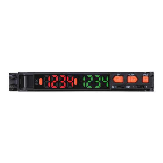
Page 3: Part Names And Functions
1. Part Names and Functions (2) Main display (red display) (3) Twin output model: Operation indicator (2CH side) Analog output model: None (1) Operation indicator (4) Sub-display (green display) (1CH) DOWN MODE (7) Control keys RUN 1 (5) SET/RUN switch (6) Twin output type: Channel switch Analog output type: Operating mode switch (1) This indicator lights when the output turns ON. -
Page 4: Basic Knowledge For Operation
Installing the Amplifier Unit Installation procedure Hook the Sensor Head connector end of the Amplifier Unit on the DIN Track and press in at the bottom until the Amplifier Unit locks into place. Be sure to mount the Amplifier Unit by hooking the Sensor Head DIN track connector end of the Amplifier Unit on the DIN Track. -
Page 5: Function Overview
5. Function Overview Function Transition Charts SET mode The following function can be set in SET mode. The following explanation is for the SET mode on both the twin output model and analog output model. Switch to the SET mode. 0. - Page 6 5. Bank selection 0 to 3 6. Bank registration 0 to 3 7. Display orientation Normal display D123 Reversed display E21P 8. Sensor model selection E4C-DS30 E4C-DS80 E4C-DS100 9. Scaling Scaling set Scaling not set * In the case of the twin output model 10.
-
Page 7: Basic Settings
6. Basic Settings 1. Setting the Head Type Initial setting of the head type Set the head type when the power is first turned ON after the Amplifier Unit is purchased. Setting procedure When the power is first turned ON, the following is displayed. Main display: Sub-display: Select the model (30, 80, 100) by the UP or DOWN key,... - Page 8 3. Setting Threshold Values 1) Teaching settings (1) Teaching with and without a workpiece Set two points one with a workpiece and another without a workpiece to be respectively sensed, and set the point between these two points as the threshold value. This setting can be made in both of the RUN and SET modes. When this setting is made in the RUN mode, make sure that the "MODE key setting"...
- Page 9 (3) Automatic-teaching (set by a moving workpiece) Measure the sensing distance while the key is held down, and set the value between the minimum and maximum distance values as the threshold value. Before making this setting, make sure that the MODE key setting is set to [AUTO]. The default setting is [2PNT]. Refer to "Function Transition Charts"...
- Page 10 2) Manual setting Manually set the threshold value. Set the threshold value by the UP or DOWN key. Operation Switch to the RUN mode. Increments the threshold value. Decrements the threshold value. After about 3 seconds, the display returns Display to the display set in the display setup.
- Page 11 5. Setting Scaling Setting procedure Main display: Sub-display: Select [9-SC] by the MODE key, and then press the UP or DOWN key once. Displays the current scaling execution state. Press the UP or DOWN key to select "ON", and press the MODE key to apply the setting. Place the workpiece at the first point, and press the MODE key.
-
Page 12: Output Settings
Cancel procedure Main display: Sub-display: Select [9-SC] by the MODE key, and then press the UP or DOWN key once. Displays the current scaling execution state. Press the UP or DOWN key to select [OFF], and press the MODE key to cancel the setting. (The display flashes twice.) Press the MODE key. - Page 13 Setting the output range (analog output model) Function • This function sets the range and display ratio of linear output with respect to the display value. • This function is mounted only on the analog output model. Note: The preset output range is canceled by initializing the product settings. Note: When the output range is set, zero reset and offset are automatically cleared.
- Page 14 Setting procedure Main display: Sub-display: Select [10AR] by the MODE key, and then press the UP or DOWN key to select [RFCT]. Press the MODE key to apply the setting. The current distance is displayed on the sub-display. Align with the rear, and hold down the MODE key for more than 3 seconds.
-
Page 15: Handy Ways Of Setting Functions
7. Handy Ways of Setting Functions Setting the Display to Zero (zero reset) Before making this setting, make sure that the "MODE key setting" is set to [0RST] (zero reset). The default setting is [2PNT] (teaching with and without a workpiece). (Refer to "Function Transition Charts" in "5. Function Overview.") Setting method Cancel method... - Page 16 Keylock Setting method Cancel method Switch to the RUN mode. Switch to the RUN mode. Hold down the UP key for more Hold down the UP key for more than 3 seconds with the MODE than 3 seconds with the MODE key pressed.
- Page 17 8. Ratings Ratings and Specifications Type Twin output model Analog output model Model E4C-UDA11 E4C-UDA41 E4C-UDA11AN E4C-UDA41AN NPNoutput PNPoutput NPNoutput PNPoutput Connection method Prewired Supply voltage 12 to 24 VDC ± 10%, ripple 10% max. Current consumption 80 mA max. Control output NPN open collector (26.4 VDC max.) Load current: 50 mA max., Residual voltage: 1 V max.
-
Page 18: External Dimensions
S ensing D evices D ivision H.Q. A pplication S ensors D ivision Shiokoji Horikawa, Shimogyo-ku,Kyoto, 600-8530 Japan Tel: (81)75-344-7068/Fax: (81)75-344-7107 R egional H eadquarters OMRON ASIA P ACIFIC PTE. LT D. OMRON E UROPE B.V. 83 Clemenceau Avenue, Sensor Business Unit, #11-01, UE Square, Carl-Benz-Str.
Need help?
Do you have a question about the E4C-UDA and is the answer not in the manual?
Questions and answers